EP2338708B1 - Système de suspension en tandem pour véhicule avec pivot intégré dans le chassis du véhicule - Google Patents
Système de suspension en tandem pour véhicule avec pivot intégré dans le chassis du véhicule Download PDFInfo
- Publication number
- EP2338708B1 EP2338708B1 EP09425533.8A EP09425533A EP2338708B1 EP 2338708 B1 EP2338708 B1 EP 2338708B1 EP 09425533 A EP09425533 A EP 09425533A EP 2338708 B1 EP2338708 B1 EP 2338708B1
- Authority
- EP
- European Patent Office
- Prior art keywords
- support
- pivot
- leaf spring
- vehicle
- tandem suspension
- Prior art date
- Legal status (The legal status is an assumption and is not a legal conclusion. Google has not performed a legal analysis and makes no representation as to the accuracy of the status listed.)
- Not-in-force
Links
- 239000000725 suspension Substances 0.000 title claims description 32
- 238000012423 maintenance Methods 0.000 description 3
- 238000005096 rolling process Methods 0.000 description 3
- 229910001018 Cast iron Inorganic materials 0.000 description 2
- 238000009434 installation Methods 0.000 description 2
- 238000004519 manufacturing process Methods 0.000 description 2
- 239000000463 material Substances 0.000 description 2
- 230000002787 reinforcement Effects 0.000 description 2
- 238000012856 packing Methods 0.000 description 1
Images



Classifications
-
- B—PERFORMING OPERATIONS; TRANSPORTING
- B60—VEHICLES IN GENERAL
- B60G—VEHICLE SUSPENSION ARRANGEMENTS
- B60G5/00—Resilient suspensions for a set of tandem wheels or axles having interrelated movements
- B60G5/02—Resilient suspensions for a set of tandem wheels or axles having interrelated movements mounted on a single pivoted arm, e.g. the arm being rigid
- B60G5/03—Resilient suspensions for a set of tandem wheels or axles having interrelated movements mounted on a single pivoted arm, e.g. the arm being rigid the arm itself being resilient, e.g. a leafspring
-
- B—PERFORMING OPERATIONS; TRANSPORTING
- B60—VEHICLES IN GENERAL
- B60G—VEHICLE SUSPENSION ARRANGEMENTS
- B60G2202/00—Indexing codes relating to the type of spring, damper or actuator
- B60G2202/10—Type of spring
- B60G2202/11—Leaf spring
- B60G2202/112—Leaf spring longitudinally arranged
-
- B—PERFORMING OPERATIONS; TRANSPORTING
- B60—VEHICLES IN GENERAL
- B60G—VEHICLE SUSPENSION ARRANGEMENTS
- B60G2204/00—Indexing codes related to suspensions per se or to auxiliary parts
- B60G2204/10—Mounting of suspension elements
- B60G2204/12—Mounting of springs or dampers
- B60G2204/121—Mounting of leaf springs
-
- B—PERFORMING OPERATIONS; TRANSPORTING
- B60—VEHICLES IN GENERAL
- B60G—VEHICLE SUSPENSION ARRANGEMENTS
- B60G2204/00—Indexing codes related to suspensions per se or to auxiliary parts
- B60G2204/40—Auxiliary suspension parts; Adjustment of suspensions
- B60G2204/43—Fittings, brackets or knuckles
- B60G2204/4302—Fittings, brackets or knuckles for fixing suspension arm on the vehicle body or chassis
Definitions
- the present invention relates to a tandem suspension system for a vehicle, with pivot integrated in the vehicle frame.
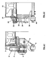
- a tandem suspension system known in the art is shown for example in figures 1 and 2.1 , respectively in a side and in a cross view.
- Other examples of known suspension system are disclosed in FR 1 296 474 and in DE 1047033 .
- the system allows the suspension of two axles 1, 2, possibly both being driving axles, and is connected to the side members 3 of the vehicle.
- a bearing structure 4 called “vertical elongated arm”, projecting from the lower part of the side member, from which the pivot 5 of the suspension projects, in a position underneath the side member.
- a leaf spring package 6 is fixed on the pivot 5 by means of a pair of U bolts 7, so that it can oscillate around the pivot. The ends of the leaf spring package engage the vehicle axles, determining its suspension.
- a pair of reaction rods 8 are hinged to, and connect in an oscillating way, the axles of the vehicle 1, 2 to the lower end of the vertical elongated arm 4.
- the oscillating structure of the tandem suspension rotates around the pivot fixed to the vertical elongated arm, from which it projects.
- the oscillating part is mounted on the projecting part of the pivot with respect to the vertical elongated arm that, in its turn, is fixed under the side member.
- the structure is very heavy, because of both the vertical elongated arm bearing structure, which is made of cast iron, and the pivot, which needs to have a considerable diameter, since it is a projecting part. This determines an increase of the vehicle's weight to the detriment of its carrying capacity.
- the shape of the vertical elongated arm is not suitable for reacting to the longitudinal loads transmitted to the reaction rods.
- the aim of the present invention is to provide a tandem suspension with the pivot integrated in the frame of a vehicle, and vehicle comprising said suspension, suitable for overcoming all the drawbacks mentioned above.
- the subject of the present invention is a tandem suspension for two vehicle axles, comprising at least a leaf spring for each side of the vehicle, said leaf spring being connected in its middle part to a support, while its ends are connected to said axles, characterized in that at each one of the sides of the vehicle said support is laterally and externally connected to a side member of the vehicle frame, said support being positionned only laterally to said side member in a position comprised between the lower part of the side of said side member and the upper part of the side of said side member when said member is in position in the vehicle and includes a pivot to which the leaf spring is connected centrally and the bottom, in a horizontally pivoted way, the pivot being placed at the side of the side member, leaning against both ends on the support.
- the subject of the present invention is in particular to a tandem suspension with the pivot integrated in the frame of a vehicle, and vehicle comprising said suspension, as described more fully in the claims, which are an integral part of this description.
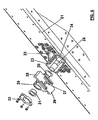
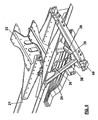
- Figures from 2.2 to 8 show examples of tandem suspensions according to the present invention.
- a side member 21 is shown having a reinforcement cross member 22.
- the support preferably comprises reinforcement elongated arms 25 and has a semi-cilindrical shape, open at the bottom. The support and the pivot are positioned laterally to the side member, within its width.
- the lower shape of the latter is such as to adapt to the upper surface of the leaf spring packet, preferably flattened, with a pair of side wings 28 which extend by projecting with respect to the middle part 29 having a hollow cylinder shape, so that it can internally house the pivot.
- the side wings comprise an upper cavity.
- a pair of bush bearings 30, 31, preferably of the sliding type, are driven into the ends of the pivot 24, and are placed between the pivot and the internal surface of the middle part 29 of the oscillating support.
- the bearings also have side shoulders 44, 45, in order to seal to the borders of the oscillating support.
- a cap 32 externally covers the support, and comprises an internal cavity 33 where the external end of the pivot 24 is housed along with the bush bearing 31. The other internal end 34 of the pivot 24 is fixed into the support 23.
- the leaf spring packet 26 is fixed to the horizontally pivoted support 27 by means of a pair of U bolts 35, 36 whose upper end is housed in the corresponding cavity of the wings 28.
- the U bolts 35, 36 are tighten to the leaf spring packet by a screwing on a plate 37 which closes the lower part of the leaf spring packet.
- a support for the reaction rods is provided and consists of a pair of V-shaped tubulars 38, 39, connected to the lower part of the side member 21, in order to obtain a triangle, which closes on a lower support 40, suitable to house the oscillating pivots of the reaction rods 41, 42.
- the reaction rod support is independent and is separate from the suspension system.
- the other ends of the reaction rods 41, 42 are fixed to the axles 43, 44 of the vehicle, as well as the ends of the leaf spring package.
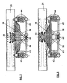
- Figures 7 shows an example of the application of the tandem suspension system according to the invention to a leaf spring package of the parabolic type 50.
- the support 23 is fixed in the lower part of the side member side 21.
- the lowered position of the support is possible since the parabolic leaves of the package may be shaped during the manufacturing in order to raise the ends, and also the package has a limited thickness.
- Figures 8 shows an example of the application of the tandem suspension system according to the invention to a leaf spring package of the semi-elliptical type 51.
- the support 23 is fixed to the upper part of the side of the side member 21, in order compensate the higher thickness of the leaf spring package with respect to the previous case.
- the pivot is simple and light, and it is not projecting, but it rests also on its front part, therefore behaving like a beam supported at both ends.
- the bearings consist of bushes of the sliding type, made of self-lubricating, sintered, very hard materials, being less thick than the bearings used in the systems known (e.g. from 160mm to 55mm).
- the support of the reaction rods has a structure independent from the suspension, which is very light, for example made of tubular.
- the support of the pivot can be opened.
- the pivot is driven into the support from behind.
- the support may be made of cast iron and is external bench mounted, off line, before the installation on the frame, which reduces maintenance costs, because, in case an intervention is needed, it is enough to remove the cap and to the oscillating support off, which is integral with the leaf spring. Therefore, if it is necessary to dismantle the leaf spring, it is enough to intervene on the support.
- the leaf spring rests under the pivot, thus the support with the pivot bears the vehicle's weight.
- the U bolts are used just for packing the leaf spring, their function is no longer to hold the whole vehicle. The advantage of increasing the safety and reducing the weight of the whole system is evident.
- the U bolts may have just the function of tightening the spring to the oscillating support, but it has no longer the function to bear the weight of the whole vehicle load, as in the system of the type known in the art.
- the U bolts may have a smaller diameter, being also more reliable.
- the pivot integrated in the support uses a double support, while the pivot of the system known in the art, being a projecting part, uses a single support. This allows a considerable reduction of the dimensions of the pivot, with the same vehicle load.
- the support of the pivot made of two parts can be easily assembled to the oscillating support, to which the sliding bearings have previously been added, by driving them into it.
- the support, along with the pivot and the oscillating support, is then assembled to the frame in its different positions, as a function of its usage with parabolic or with semi-elliptical springs. During the maintenance it is possible to replace the sliding bearings without dismantling the pivot support from the frame.
- the support of the reaction rods having just the function of fixing them, unlike the support of the system known in the art, which also has to support the pivot, may be realized by means of a simplified technology.
Landscapes
- Engineering & Computer Science (AREA)
- Mechanical Engineering (AREA)
- Vehicle Body Suspensions (AREA)
Claims (9)
- Suspension en tandem pour un véhicule comportant au moins deux essieux, comprenant au moins un ressort à lames pour chaque côté du véhicule, ledit ressort à lames étant raccordé dans sa partie de milieu à un support, alors que ses extrémités sont raccordées auxdits essieux, caractérisée en ce que à chacun des côtés du véhicule, ledit support (23) est latéralement et extérieurement raccordé à un organe latéral (21) de la caisse de véhicule, ledit support (23) étant positionné uniquement latéralement audit organe latéral (21) dans une position comprise entre la partie inférieure du côté dudit organe latéral (21) et la partie supérieure du côté dudit organe latéral (21) lorsque ledit organe (21) est en position dans le véhicule, et inclut un pivot (24) auquel le ressort à lames est raccordé centralement et au fond, de manière horizontalement pivotée, le pivot étant placé au niveau du côté de l'organe latéral, reposant contre les deux extrémités sur le support.
- Suspension en tandem selon la revendication 1, dans laquelle le fond du support a une forme ouverte et le ressort à lames (26) est fixé au pivot (24), en dessous à la fois du pivot et du support (23), au moyen d'un support oscillant.
- Suspension en tandem selon la revendication 1, dans laquelle la forme inférieure dudit support oscillant (26) est telle à s'adapter à la surface supérieure du ressort à lames, et comprend une paire d'ailes latérales (28) qui s'étendent en faisant saillie par rapport à la partie milieu (29) ayant une forme de cylindre creux, de sorte qu'elle puisse loger intérieurement le pivot.
- Suspension en tandem selon la revendication 3, comprenant en outre :- au moins une paire de paliers lisses (30, 31) entraînés dans les extrémités du pivot (24), et placés entre le pivot et la surface interne de la partie milieu (29) du support oscillant ;- au moins une coiffe (32) convenant pour fermer extérieurement le support, la coiffe comprenant un compartiment pour l'extrémité externe du pivot, avec son palier lisse respectif, l'autre extrémité interne (34) du pivot étant entraînée dans le support.
- Suspension en tandem selon la revendication 3, comprenant en outre une paire de boulons en U (35 ; 36) convenant à une fixation du ressort à lames (26) au support oscillant (27), l'extrémité supérieure du boulon en U étant logée dans lesdites ailes latérales (28).
- Suspension en tandem selon la revendication 1, dans laquelle ledit ressort à lames est une enveloppe de ressort à lames du type parabolique (50) lorsque ledit support (23) est fixé à la partie inférieure du côté de l'organe latéral (21).
- Suspension en tandem selon la revendication 1, dans laquelle ledit ressort à lames est une enveloppe de ressort à lames du type semi-elliptique (51) lorsque ledit support (23) est fixé à la partie supérieure du côté de l'organe latéral (21).
- Véhicule comprenant une suspension en tandem selon l'une quelconque des revendications précédentes.
- Véhicule selon la revendication 8, comprenant un support pour des jambes de réaction raccordées auxdits deux essieux, ledit support étant raccordé à la partie inférieure de l'organe latéral (21), de manière indépendante et séparée de ladite suspension en tandem.
Priority Applications (4)
| Application Number | Priority Date | Filing Date | Title |
|---|---|---|---|
| EP09425533.8A EP2338708B1 (fr) | 2009-12-24 | 2009-12-24 | Système de suspension en tandem pour véhicule avec pivot intégré dans le chassis du véhicule |
| ES09425533.8T ES2457191T3 (es) | 2009-12-24 | 2009-12-24 | Sistema de suspensión en tándem para un vehículo con pivote integrado en el chasis del vehículo |
| CN201010600462.9A CN102107596B (zh) | 2009-12-24 | 2010-12-22 | 具有集成于车架内的枢轴的车辆平衡悬架系统 |
| BRPI1013451-4A BRPI1013451B1 (pt) | 2009-12-24 | 2010-12-24 | sistema de suspensão de eixo em tandem para um veículo, com pivô integrado no chassi do veículo |
Applications Claiming Priority (1)
| Application Number | Priority Date | Filing Date | Title |
|---|---|---|---|
| EP09425533.8A EP2338708B1 (fr) | 2009-12-24 | 2009-12-24 | Système de suspension en tandem pour véhicule avec pivot intégré dans le chassis du véhicule |
Publications (2)
| Publication Number | Publication Date |
|---|---|
| EP2338708A1 EP2338708A1 (fr) | 2011-06-29 |
| EP2338708B1 true EP2338708B1 (fr) | 2014-01-15 |
Family
ID=42169505
Family Applications (1)
| Application Number | Title | Priority Date | Filing Date |
|---|---|---|---|
| EP09425533.8A Not-in-force EP2338708B1 (fr) | 2009-12-24 | 2009-12-24 | Système de suspension en tandem pour véhicule avec pivot intégré dans le chassis du véhicule |
Country Status (4)
| Country | Link |
|---|---|
| EP (1) | EP2338708B1 (fr) |
| CN (1) | CN102107596B (fr) |
| BR (1) | BRPI1013451B1 (fr) |
| ES (1) | ES2457191T3 (fr) |
Families Citing this family (1)
| Publication number | Priority date | Publication date | Assignee | Title |
|---|---|---|---|---|
| CN102582390B (zh) * | 2012-03-02 | 2014-05-28 | 潍柴动力股份有限公司 | 一种平衡悬架及应用该平衡悬架的汽车 |
Family Cites Families (6)
| Publication number | Priority date | Publication date | Assignee | Title |
|---|---|---|---|---|
| GB246703A (en) * | 1925-04-29 | 1926-02-04 | Int Motor Co | Improvements in and relating to spring suspension for motor vehicles |
| US2002152A (en) * | 1933-10-23 | 1935-05-21 | Nelson Le Moon Truck Company | Axle mounting |
| DE1047033B (de) * | 1954-11-12 | 1958-12-18 | Daimler Benz Ag | Abfederung doppelter Hinterrad-Starrachsen |
| FR1296474A (fr) * | 1960-08-08 | 1962-06-15 | Eaton Mfg Co | Dispositif de suspension pour véhicules |
| DE4309004A1 (de) * | 1993-03-20 | 1994-09-22 | Man Nutzfahrzeuge Ag | Lenkergeführtes Doppelachsaggregat |
| SE524632C2 (sv) * | 2002-02-28 | 2004-09-07 | Volvo Lastvagnar Ab | Lagringsanordning samt metod för lagring av fjäderupphängningen till en bladfjädrad boggi på ett fordon |
-
2009
- 2009-12-24 EP EP09425533.8A patent/EP2338708B1/fr not_active Not-in-force
- 2009-12-24 ES ES09425533.8T patent/ES2457191T3/es active Active
-
2010
- 2010-12-22 CN CN201010600462.9A patent/CN102107596B/zh not_active Expired - Fee Related
- 2010-12-24 BR BRPI1013451-4A patent/BRPI1013451B1/pt not_active IP Right Cessation
Also Published As
| Publication number | Publication date |
|---|---|
| EP2338708A1 (fr) | 2011-06-29 |
| CN102107596A (zh) | 2011-06-29 |
| CN102107596B (zh) | 2014-12-17 |
| BRPI1013451A2 (pt) | 2016-01-26 |
| ES2457191T3 (es) | 2014-04-25 |
| BRPI1013451B1 (pt) | 2020-10-20 |
Similar Documents
| Publication | Publication Date | Title |
|---|---|---|
| US8827289B2 (en) | Reduced weight axle mounting assembly for vehicle suspension systems | |
| US9073400B2 (en) | Motor vehicle multi-link suspension system including a transverse leaf spring | |
| CA2836136C (fr) | Ensemble soupape de reglage de hauteur pour systemes essieu/suspension | |
| CN201086615Y (zh) | 断开式平衡悬架及具有该悬架的重型卡车 | |
| US4502707A (en) | Tandem axle suspension system | |
| CN107264219A (zh) | 一种矿用车后悬架总成 | |
| EP1901931A1 (fr) | Ressort en cahoutchouc pour une suspension d'axe de roues de vehicule | |
| EP2338708B1 (fr) | Système de suspension en tandem pour véhicule avec pivot intégré dans le chassis du véhicule | |
| CN209920975U (zh) | 一种气囊全承载空气悬架结构 | |
| CN102275478B (zh) | 矿用车用悬架装置 | |
| ES2959605T3 (es) | Lámina de resorte para una ballesta | |
| US20050034394A1 (en) | System for articulably bearing a prefabricated structural member on a foundation | |
| CN104773044A (zh) | 一种低速牵引车用悬挂装置 | |
| US9527357B2 (en) | Trunnion suspension structure | |
| US20070052195A1 (en) | Light truck support lift | |
| CN203835166U (zh) | 一种自平衡机车司机室内上下活动侧窗 | |
| EP2886504A1 (fr) | Grappin mécanique pour soulever et transporter des charges | |
| CN205871667U (zh) | 一种平衡轴悬架总成 | |
| CN202847369U (zh) | 悬架组件、具有该悬架组件的悬架和具有该悬架的车辆 | |
| CN105857002B (zh) | 用于车辆后桥的具有空气弹簧元件的单独车轮悬架以及相应配备的车辆后桥 | |
| RU2834094C1 (ru) | Буферный узел, механизм подвески и транспортное средство | |
| EP2380761A1 (fr) | Dispositif de fixation pour monter une suspension de roue sur un châssis de véhicule | |
| US20100171250A1 (en) | Anti-roll leaf spring suspension | |
| EP4606604A1 (fr) | Système de suspension amélioré | |
| CN208324770U (zh) | 一种集装箱空箱堆高机转向桥 |
Legal Events
| Date | Code | Title | Description |
|---|---|---|---|
| PUAI | Public reference made under article 153(3) epc to a published international application that has entered the european phase |
Free format text: ORIGINAL CODE: 0009012 |
|
| AK | Designated contracting states |
Kind code of ref document: A1 Designated state(s): AT BE BG CH CY CZ DE DK EE ES FI FR GB GR HR HU IE IS IT LI LT LU LV MC MK MT NL NO PL PT RO SE SI SK SM TR |
|
| AX | Request for extension of the european patent |
Extension state: AL BA RS |
|
| 17P | Request for examination filed |
Effective date: 20111223 |
|
| 17Q | First examination report despatched |
Effective date: 20120329 |
|
| GRAP | Despatch of communication of intention to grant a patent |
Free format text: ORIGINAL CODE: EPIDOSNIGR1 |
|
| GRAS | Grant fee paid |
Free format text: ORIGINAL CODE: EPIDOSNIGR3 |
|
| GRAP | Despatch of communication of intention to grant a patent |
Free format text: ORIGINAL CODE: EPIDOSNIGR1 |
|
| GRAA | (expected) grant |
Free format text: ORIGINAL CODE: 0009210 |
|
| INTG | Intention to grant announced |
Effective date: 20131126 |
|
| AK | Designated contracting states |
Kind code of ref document: B1 Designated state(s): AT BE BG CH CY CZ DE DK EE ES FI FR GB GR HR HU IE IS IT LI LT LU LV MC MK MT NL NO PL PT RO SE SI SK SM TR |
|
| REG | Reference to a national code |
Ref country code: GB Ref legal event code: FG4D Ref country code: CH Ref legal event code: EP |
|
| REG | Reference to a national code |
Ref country code: AT Ref legal event code: REF Ref document number: 649650 Country of ref document: AT Kind code of ref document: T Effective date: 20140215 |
|
| REG | Reference to a national code |
Ref country code: IE Ref legal event code: FG4D |
|
| REG | Reference to a national code |
Ref country code: DE Ref legal event code: R096 Ref document number: 602009021435 Country of ref document: DE Effective date: 20140227 |
|
| REG | Reference to a national code |
Ref country code: CH Ref legal event code: NV Representative=s name: N&G PATENT SERVICES SA, CH |
|
| REG | Reference to a national code |
Ref country code: SE Ref legal event code: TRGR |
|
| REG | Reference to a national code |
Ref country code: NL Ref legal event code: T3 |
|
| REG | Reference to a national code |
Ref country code: ES Ref legal event code: FG2A Ref document number: 2457191 Country of ref document: ES Kind code of ref document: T3 Effective date: 20140425 |
|
| REG | Reference to a national code |
Ref country code: AT Ref legal event code: MK05 Ref document number: 649650 Country of ref document: AT Kind code of ref document: T Effective date: 20140115 |
|
| REG | Reference to a national code |
Ref country code: LT Ref legal event code: MG4D |
|
| PG25 | Lapsed in a contracting state [announced via postgrant information from national office to epo] |
Ref country code: LT Free format text: LAPSE BECAUSE OF FAILURE TO SUBMIT A TRANSLATION OF THE DESCRIPTION OR TO PAY THE FEE WITHIN THE PRESCRIBED TIME-LIMIT Effective date: 20140115 Ref country code: NO Free format text: LAPSE BECAUSE OF FAILURE TO SUBMIT A TRANSLATION OF THE DESCRIPTION OR TO PAY THE FEE WITHIN THE PRESCRIBED TIME-LIMIT Effective date: 20140415 Ref country code: IS Free format text: LAPSE BECAUSE OF FAILURE TO SUBMIT A TRANSLATION OF THE DESCRIPTION OR TO PAY THE FEE WITHIN THE PRESCRIBED TIME-LIMIT Effective date: 20140515 |
|
| PG25 | Lapsed in a contracting state [announced via postgrant information from national office to epo] |
Ref country code: FI Free format text: LAPSE BECAUSE OF FAILURE TO SUBMIT A TRANSLATION OF THE DESCRIPTION OR TO PAY THE FEE WITHIN THE PRESCRIBED TIME-LIMIT Effective date: 20140115 Ref country code: PT Free format text: LAPSE BECAUSE OF FAILURE TO SUBMIT A TRANSLATION OF THE DESCRIPTION OR TO PAY THE FEE WITHIN THE PRESCRIBED TIME-LIMIT Effective date: 20140515 Ref country code: AT Free format text: LAPSE BECAUSE OF FAILURE TO SUBMIT A TRANSLATION OF THE DESCRIPTION OR TO PAY THE FEE WITHIN THE PRESCRIBED TIME-LIMIT Effective date: 20140115 Ref country code: CY Free format text: LAPSE BECAUSE OF FAILURE TO SUBMIT A TRANSLATION OF THE DESCRIPTION OR TO PAY THE FEE WITHIN THE PRESCRIBED TIME-LIMIT Effective date: 20140115 |
|
| PG25 | Lapsed in a contracting state [announced via postgrant information from national office to epo] |
Ref country code: BE Free format text: LAPSE BECAUSE OF FAILURE TO SUBMIT A TRANSLATION OF THE DESCRIPTION OR TO PAY THE FEE WITHIN THE PRESCRIBED TIME-LIMIT Effective date: 20140115 Ref country code: HR Free format text: LAPSE BECAUSE OF FAILURE TO SUBMIT A TRANSLATION OF THE DESCRIPTION OR TO PAY THE FEE WITHIN THE PRESCRIBED TIME-LIMIT Effective date: 20140115 Ref country code: LV Free format text: LAPSE BECAUSE OF FAILURE TO SUBMIT A TRANSLATION OF THE DESCRIPTION OR TO PAY THE FEE WITHIN THE PRESCRIBED TIME-LIMIT Effective date: 20140115 |
|
| REG | Reference to a national code |
Ref country code: DE Ref legal event code: R097 Ref document number: 602009021435 Country of ref document: DE |
|
| PG25 | Lapsed in a contracting state [announced via postgrant information from national office to epo] |
Ref country code: DK Free format text: LAPSE BECAUSE OF FAILURE TO SUBMIT A TRANSLATION OF THE DESCRIPTION OR TO PAY THE FEE WITHIN THE PRESCRIBED TIME-LIMIT Effective date: 20140115 Ref country code: RO Free format text: LAPSE BECAUSE OF FAILURE TO SUBMIT A TRANSLATION OF THE DESCRIPTION OR TO PAY THE FEE WITHIN THE PRESCRIBED TIME-LIMIT Effective date: 20140115 Ref country code: EE Free format text: LAPSE BECAUSE OF FAILURE TO SUBMIT A TRANSLATION OF THE DESCRIPTION OR TO PAY THE FEE WITHIN THE PRESCRIBED TIME-LIMIT Effective date: 20140115 Ref country code: CZ Free format text: LAPSE BECAUSE OF FAILURE TO SUBMIT A TRANSLATION OF THE DESCRIPTION OR TO PAY THE FEE WITHIN THE PRESCRIBED TIME-LIMIT Effective date: 20140115 |
|
| PLBE | No opposition filed within time limit |
Free format text: ORIGINAL CODE: 0009261 |
|
| STAA | Information on the status of an ep patent application or granted ep patent |
Free format text: STATUS: NO OPPOSITION FILED WITHIN TIME LIMIT |
|
| PG25 | Lapsed in a contracting state [announced via postgrant information from national office to epo] |
Ref country code: SK Free format text: LAPSE BECAUSE OF FAILURE TO SUBMIT A TRANSLATION OF THE DESCRIPTION OR TO PAY THE FEE WITHIN THE PRESCRIBED TIME-LIMIT Effective date: 20140115 Ref country code: PL Free format text: LAPSE BECAUSE OF FAILURE TO SUBMIT A TRANSLATION OF THE DESCRIPTION OR TO PAY THE FEE WITHIN THE PRESCRIBED TIME-LIMIT Effective date: 20140115 |
|
| 26N | No opposition filed |
Effective date: 20141016 |
|
| REG | Reference to a national code |
Ref country code: DE Ref legal event code: R097 Ref document number: 602009021435 Country of ref document: DE Effective date: 20141016 |
|
| PG25 | Lapsed in a contracting state [announced via postgrant information from national office to epo] |
Ref country code: SI Free format text: LAPSE BECAUSE OF FAILURE TO SUBMIT A TRANSLATION OF THE DESCRIPTION OR TO PAY THE FEE WITHIN THE PRESCRIBED TIME-LIMIT Effective date: 20140115 |
|
| PG25 | Lapsed in a contracting state [announced via postgrant information from national office to epo] |
Ref country code: LU Free format text: LAPSE BECAUSE OF FAILURE TO SUBMIT A TRANSLATION OF THE DESCRIPTION OR TO PAY THE FEE WITHIN THE PRESCRIBED TIME-LIMIT Effective date: 20141224 |
|
| REG | Reference to a national code |
Ref country code: IE Ref legal event code: MM4A |
|
| PG25 | Lapsed in a contracting state [announced via postgrant information from national office to epo] |
Ref country code: IE Free format text: LAPSE BECAUSE OF NON-PAYMENT OF DUE FEES Effective date: 20141224 |
|
| REG | Reference to a national code |
Ref country code: FR Ref legal event code: PLFP Year of fee payment: 7 |
|
| PG25 | Lapsed in a contracting state [announced via postgrant information from national office to epo] |
Ref country code: SM Free format text: LAPSE BECAUSE OF FAILURE TO SUBMIT A TRANSLATION OF THE DESCRIPTION OR TO PAY THE FEE WITHIN THE PRESCRIBED TIME-LIMIT Effective date: 20140115 |
|
| PG25 | Lapsed in a contracting state [announced via postgrant information from national office to epo] |
Ref country code: MC Free format text: LAPSE BECAUSE OF FAILURE TO SUBMIT A TRANSLATION OF THE DESCRIPTION OR TO PAY THE FEE WITHIN THE PRESCRIBED TIME-LIMIT Effective date: 20140115 |
|
| PG25 | Lapsed in a contracting state [announced via postgrant information from national office to epo] |
Ref country code: BG Free format text: LAPSE BECAUSE OF FAILURE TO SUBMIT A TRANSLATION OF THE DESCRIPTION OR TO PAY THE FEE WITHIN THE PRESCRIBED TIME-LIMIT Effective date: 20140115 Ref country code: GR Free format text: LAPSE BECAUSE OF FAILURE TO SUBMIT A TRANSLATION OF THE DESCRIPTION OR TO PAY THE FEE WITHIN THE PRESCRIBED TIME-LIMIT Effective date: 20140416 |
|
| PG25 | Lapsed in a contracting state [announced via postgrant information from national office to epo] |
Ref country code: HU Free format text: LAPSE BECAUSE OF FAILURE TO SUBMIT A TRANSLATION OF THE DESCRIPTION OR TO PAY THE FEE WITHIN THE PRESCRIBED TIME-LIMIT; INVALID AB INITIO Effective date: 20091224 Ref country code: MT Free format text: LAPSE BECAUSE OF FAILURE TO SUBMIT A TRANSLATION OF THE DESCRIPTION OR TO PAY THE FEE WITHIN THE PRESCRIBED TIME-LIMIT Effective date: 20140115 Ref country code: TR Free format text: LAPSE BECAUSE OF FAILURE TO SUBMIT A TRANSLATION OF THE DESCRIPTION OR TO PAY THE FEE WITHIN THE PRESCRIBED TIME-LIMIT Effective date: 20140115 |
|
| REG | Reference to a national code |
Ref country code: FR Ref legal event code: PLFP Year of fee payment: 8 |
|
| REG | Reference to a national code |
Ref country code: FR Ref legal event code: PLFP Year of fee payment: 9 |
|
| PG25 | Lapsed in a contracting state [announced via postgrant information from national office to epo] |
Ref country code: MK Free format text: LAPSE BECAUSE OF FAILURE TO SUBMIT A TRANSLATION OF THE DESCRIPTION OR TO PAY THE FEE WITHIN THE PRESCRIBED TIME-LIMIT Effective date: 20140115 |
|
| REG | Reference to a national code |
Ref country code: CH Ref legal event code: NV Representative=s name: ISLER AND PEDRAZZINI AG, CH Ref country code: CH Ref legal event code: PLI Free format text: LICENCE NON-EXCLUSIVE Name of requester: IVECO S.P.A., IT Ref country code: CH Ref legal event code: PUE Owner name: E.M.T.B. ENGINEERING MACHINERY TOOLING BOLZANO, IT Free format text: FORMER OWNER: IVECO S.P.A., IT Ref country code: CH Ref legal event code: PUE Owner name: STREPARAVA S.P.A., IT Free format text: FORMER OWNER: E.M.T.B. ENGINEERING MACHINERY TOOLING BOLZANO S.R.L., IT |
|
| REG | Reference to a national code |
Ref country code: ES Ref legal event code: PC2A Owner name: E.M.T.B. ENGINEERING MACHINERY TOOLING BOLZANO S.R Effective date: 20190329 |
|
| REG | Reference to a national code |
Ref country code: ES Ref legal event code: GD2A Effective date: 20190412 |
|
| REG | Reference to a national code |
Ref country code: CH Ref legal event code: PFA Owner name: STREPARAVA S.P.A. CON SOCIO UNICO, IT Free format text: FORMER OWNER: STREPARAVA S.P.A., IT |
|
| REG | Reference to a national code |
Ref country code: DE Ref legal event code: R082 Ref document number: 602009021435 Country of ref document: DE Representative=s name: MANITZ FINSTERWALD PATENT- UND RECHTSANWALTSPA, DE Ref country code: DE Ref legal event code: R081 Ref document number: 602009021435 Country of ref document: DE Owner name: STREPARAVA S.P.A. CON SOCIO UNICO, IT Free format text: FORMER OWNER: IVECO S.P.A., TORINO, IT Ref country code: DE Ref legal event code: R081 Ref document number: 602009021435 Country of ref document: DE Owner name: STREPARAVA S.P.A. CON SOCIO UNICO, IT Free format text: FORMER OWNER: E. M.T.B. ENGINEERING MACHINERY TOOLING BOLZANO S.R.L., BOLZANO, IT |
|
| REG | Reference to a national code |
Ref country code: ES Ref legal event code: PC2A Owner name: STREPARAVA S.P.A. CON SOCIO UNICO Effective date: 20190503 |
|
| REG | Reference to a national code |
Ref country code: NL Ref legal event code: PD Owner name: STREPARAVA S.P.A. CON SOCIO UNICO; IT Free format text: DETAILS ASSIGNMENT: CHANGE OF OWNER(S), ASSIGNMENT; FORMER OWNER NAME: IVECO S.P.A. Effective date: 20190328 Ref country code: NL Ref legal event code: QB Free format text: DETAILS LICENCE OR PLEDGE: LICENCE, NEW LICENCE REGISTRATION Name of requester: IVECO S.P.A. Effective date: 20190328 |
|
| REG | Reference to a national code |
Ref country code: GB Ref legal event code: 732E Free format text: REGISTERED BETWEEN 20190516 AND 20190522 |
|
| REG | Reference to a national code |
Ref country code: GB Ref legal event code: 732E Free format text: REGISTERED BETWEEN 20190523 AND 20190529 |
|
| PGFP | Annual fee paid to national office [announced via postgrant information from national office to epo] |
Ref country code: FR Payment date: 20211227 Year of fee payment: 13 Ref country code: GB Payment date: 20211221 Year of fee payment: 13 Ref country code: SE Payment date: 20211222 Year of fee payment: 13 |
|
| PGFP | Annual fee paid to national office [announced via postgrant information from national office to epo] |
Ref country code: IT Payment date: 20211209 Year of fee payment: 13 Ref country code: CH Payment date: 20211222 Year of fee payment: 13 |
|
| PGFP | Annual fee paid to national office [announced via postgrant information from national office to epo] |
Ref country code: NL Payment date: 20211229 Year of fee payment: 13 |
|
| PGFP | Annual fee paid to national office [announced via postgrant information from national office to epo] |
Ref country code: DE Payment date: 20211228 Year of fee payment: 13 |
|
| PGFP | Annual fee paid to national office [announced via postgrant information from national office to epo] |
Ref country code: ES Payment date: 20220110 Year of fee payment: 13 |
|
| REG | Reference to a national code |
Ref country code: DE Ref legal event code: R119 Ref document number: 602009021435 Country of ref document: DE |
|
| REG | Reference to a national code |
Ref country code: CH Ref legal event code: PL |
|
| REG | Reference to a national code |
Ref country code: SE Ref legal event code: EUG |
|
| REG | Reference to a national code |
Ref country code: NL Ref legal event code: MM Effective date: 20230101 |
|
| GBPC | Gb: european patent ceased through non-payment of renewal fee |
Effective date: 20221224 |
|
| PG25 | Lapsed in a contracting state [announced via postgrant information from national office to epo] |
Ref country code: NL Free format text: LAPSE BECAUSE OF NON-PAYMENT OF DUE FEES Effective date: 20230101 |
|
| PG25 | Lapsed in a contracting state [announced via postgrant information from national office to epo] |
Ref country code: SE Free format text: LAPSE BECAUSE OF NON-PAYMENT OF DUE FEES Effective date: 20221225 Ref country code: LI Free format text: LAPSE BECAUSE OF NON-PAYMENT OF DUE FEES Effective date: 20221231 Ref country code: GB Free format text: LAPSE BECAUSE OF NON-PAYMENT OF DUE FEES Effective date: 20221224 Ref country code: DE Free format text: LAPSE BECAUSE OF NON-PAYMENT OF DUE FEES Effective date: 20230701 Ref country code: CH Free format text: LAPSE BECAUSE OF NON-PAYMENT OF DUE FEES Effective date: 20221231 |
|
| PG25 | Lapsed in a contracting state [announced via postgrant information from national office to epo] |
Ref country code: FR Free format text: LAPSE BECAUSE OF NON-PAYMENT OF DUE FEES Effective date: 20221231 |
|
| PG25 | Lapsed in a contracting state [announced via postgrant information from national office to epo] |
Ref country code: IT Free format text: LAPSE BECAUSE OF NON-PAYMENT OF DUE FEES Effective date: 20221224 |
|
| REG | Reference to a national code |
Ref country code: ES Ref legal event code: FD2A Effective date: 20240202 |
|
| PG25 | Lapsed in a contracting state [announced via postgrant information from national office to epo] |
Ref country code: ES Free format text: LAPSE BECAUSE OF NON-PAYMENT OF DUE FEES Effective date: 20221225 |
|
| PG25 | Lapsed in a contracting state [announced via postgrant information from national office to epo] |
Ref country code: ES Free format text: LAPSE BECAUSE OF NON-PAYMENT OF DUE FEES Effective date: 20221225 |