EP2339072A2 - Appareil de traitement de sol doté d'un agencement d'arbres de travail entraînés - Google Patents
Appareil de traitement de sol doté d'un agencement d'arbres de travail entraînés Download PDFInfo
- Publication number
- EP2339072A2 EP2339072A2 EP10195458A EP10195458A EP2339072A2 EP 2339072 A2 EP2339072 A2 EP 2339072A2 EP 10195458 A EP10195458 A EP 10195458A EP 10195458 A EP10195458 A EP 10195458A EP 2339072 A2 EP2339072 A2 EP 2339072A2
- Authority
- EP
- European Patent Office
- Prior art keywords
- housing
- housing shell
- shell portion
- cultivation device
- soil cultivation
- Prior art date
- Legal status (The legal status is an assumption and is not a legal conclusion. Google has not performed a legal analysis and makes no representation as to the accuracy of the status listed.)
- Granted
Links
Images



Classifications
-
- E—FIXED CONSTRUCTIONS
- E01—CONSTRUCTION OF ROADS, RAILWAYS, OR BRIDGES
- E01H—STREET CLEANING; CLEANING OF PERMANENT WAYS; CLEANING BEACHES; DISPERSING OR PREVENTING FOG IN GENERAL CLEANING STREET OR RAILWAY FURNITURE OR TUNNEL WALLS
- E01H4/00—Working on surfaces of snow or ice in order to make them suitable for traffic or sporting purposes, e.g. by compacting snow
- E01H4/02—Working on surfaces of snow or ice in order to make them suitable for traffic or sporting purposes, e.g. by compacting snow for sporting purposes, e.g. preparation of ski trails; Construction of artificial surfacings for snow or ice sports ; Trails specially adapted for on-the-snow vehicles, e.g. devices adapted for ski-trails
-
- A—HUMAN NECESSITIES
- A01—AGRICULTURE; FORESTRY; ANIMAL HUSBANDRY; HUNTING; TRAPPING; FISHING
- A01B—SOIL WORKING IN AGRICULTURE OR FORESTRY; PARTS, DETAILS, OR ACCESSORIES OF AGRICULTURAL MACHINES OR IMPLEMENTS, IN GENERAL
- A01B33/00—Tilling implements with rotary driven tools, e.g. in combination with fertiliser distributors or seeders, with grubbing chains, with sloping axles, with driven discs
- A01B33/02—Tilling implements with rotary driven tools, e.g. in combination with fertiliser distributors or seeders, with grubbing chains, with sloping axles, with driven discs with tools on horizontal shaft transverse to direction of travel
- A01B33/021—Tilling implements with rotary driven tools, e.g. in combination with fertiliser distributors or seeders, with grubbing chains, with sloping axles, with driven discs with tools on horizontal shaft transverse to direction of travel with rigid tools
- A01B33/024—Tilling implements with rotary driven tools, e.g. in combination with fertiliser distributors or seeders, with grubbing chains, with sloping axles, with driven discs with tools on horizontal shaft transverse to direction of travel with rigid tools with disk-like tools
Definitions
- the invention relates to a harrow with a driven working shaft assembly which is rotatably mounted in a processing housing open to the ground.
- Such tillage equipment can be used in the agricultural sector or even in the snowplow design and care.
- Such a soil tillage implement in the form of a rear tiller for a tracked vehicle for snow grooming is well known.
- the rear tiller is attached by means of a mounting frame to the rear of a corresponding snow groomer.
- the rear tiller is driven by one or more hydraulic motors, which are fed and controlled via a vehicle-side hydraulics of the snow groomer.
- the rear tiller has a milling housing, in which several auger shafts are arranged in a side-by-side alignment and are rotatably mounted.
- the milling housing covers the milling shafts hood-like and is after open at the bottom. In the normal direction of travel towards the rear, the milling housing is followed by a smoothing device, also referred to as a finisher, which comprises a flexible smoothing structure.
- the cutting shafts pick up chunks of snow and ice and crush them during rotation between the blades of the milling shaft and an inner wall of the milling housing.
- the inner wall of the milling housing serves as a baffle on which the snow and ice chunks bounce and are thrown back to then be thrown again by the blades of the milling shaft against the inner wall. This results in the desired crushing of snow and ice chunks.
- the processed snow and ice residues fall back onto the slope surface and are compacted and smoothed by the smoothing formation. This creates the machined slope surface.
- the object of the invention is to provide a harrow of the type mentioned, which allows a variable tillage.
- the processing housing has at least two housing shell sections which are mounted in a fan-like manner relative to one another in the circumferential direction relative to a rotation axis of the working shaft arrangement.
- a usable baffle of the processing housing is variable between a first end position in which the processing housing surrounds the working shaft assembly over a first circumferential angle, and a second end position in which complement the at least one first housing shell portion and the at least one second housing shell portion in the circumferential direction and so surround the working shaft arrangement over a larger circumferential angle.
- the housing shell sections are preferably continuously adjustable relative to one another.
- the working shaft arrangement can be made a single or multiple, aligned in parallel juxtaposed working waves. The individual working shafts can be driven together or separately.
- the processing housing can be subdivided over a processing width of the harrow into a plurality of housing sections, which are preferably each assigned a single working shaft and which each have at least one displaceable housing shell section and a stationary housing shell section. It is also possible to provide more than two housing shell sections displaceable relative to each other in the circumferential direction.
- the solution according to the invention can be used in a particularly advantageous manner in a cultivator in the form of a tail mill for a snow groomer, as has already been described in the introduction from its basic function.
- the inventive variability of the housing shell of the milling housing it is possible depending on the type of snow surface to be machined to set the housing shell larger or smaller.
- a housing shell is sufficient over a smaller circumferential angle.
- the housing shell sections are thus fanned out in the circumferential direction or pushed over one another.
- the solution according to the invention is suitable in the same way for tillage equipment in agriculture, especially for arable cultivation.
- At least one stationary housing shell portion and at least one movable housing portion are provided, wherein the movable housing portion relative to the stationary housing shell portion - seen relative to the axis of rotation of the working shaft assembly in the circumferential direction - such is slidably mounted, that in one end position, the housing shell sections are superimposed on each other in the circumferential direction, and that in the other end position, the at least one housing shell portion extends the at least one stationary housing shell portion substantially aligned.
- the closing of the processing housing - on a machining direction - on the back of a smoothing device for compacting the machined soil which has a flexible smoothing structure, which is attached to the movable housing shell portion or to the stationary housing shell portion.
- the stationary housing shell portion remains stationary in a tillage implement in the form of a rear tiller relative to a mounting frame of the snow groomer, as he is pulled through the snow groomer.
- the slidable housing shell portion is movably disposed relative to the stationary housing shell portion.
- the stationary housing shell portion can basically be adjusted together with the entire milling housing in different positions relative to the snow groomer, as is generally known for tail milling of snow groomers.
- the smoothing device compacts and smoothes the soil processed by the working shaft arrangement and the processing housing. This refinement can be used particularly advantageously in a tail mill for a snow groomer, since the smoothing device shapes the runway image of the processed snow runway surface.
- the snow and ice residues which were previously greatly reduced by the rear tiller, are compacted and smoothed to form a snow slope that is easy for skiers or snowboarders to reach.
- drive means are provided to adjust the at least one movable housing shell portion in different positions and in the respectively set Secure positions.
- the drive means comprise at least one hydraulic cylinder which engages the displaceable housing shell portion.
- the movable housing shell portion on an arcuate in cross-section wall which covers the stationary housing shell portion in the circumferential direction on the inside at least substantially.
- a double wall is formed, in which the arcuate wall of the displaceable housing shell portion on the inside conforms to an inner wall of the stationary housing shell portion.
- the arcuate wall of the displaceable housing shell portion and the inner wall of the stationary housing shell portion define - depending on the displacement position - the baffle for soil particles that are thrown by the working shaft assembly against the inside of the processing housing.
- the bottom-shaped wall is designed as a shock-resistant, in particular sound-insulating and at least substantially dimensionally stable sheet, in particular made of plastic.
- the fabric can be implemented in one or more layers.
- a surface of the sheet which is directed toward the working shaft arrangement has a smooth surface in order to at least largely avoid adhesion of soil or dirt particles.
- the wall is held on a support profile from which the wall protrudes freely, and which is guided by means of guide assemblies on the outside of the at least one stationary housing shell portion slidably.
- the carrier profile preferably extends over the working width of the working housing or over a working width of a corresponding housing section.
- the carrier profile is arranged adjacent to a longitudinal side edge of the stationary housing shell section.
- the longitudinal side edge preferably forms a - seen in the normal machining direction - the rear boundary, which extends over the working width of the working housing.
- the guide assemblies arcuate guide runners, which are guided in guide profiles on the outer circumference of the at least one stationary housing shell portion slidably. This allows safe guidance and storage of the displaceable housing shell section.
- the guide skids have sliding surface sections with reduced sliding friction coefficients.
- arcuate guide webs are provided on opposite end-side housing terminations of the processing housing, which lead opposite side edges of the arcuate wall. This configuration ensures that the wall of the displaceable housing shell portion is guided securely on its opposite end faces in order to ensure a slidable against the inner wall of the stationary housing shell portion displaceability.
- the guidance of the arcuate wall over the end guide webs reduces the risk that soil particles, especially snow or ice chunks, press between the arcuate wall and the inner wall of the stationary housing shell portion.
- a surface area of the wall lying on the carrier profile is connected to the guide runners via securing means, wherein the securing means project through longitudinal slots in the stationary housing jacket section.
- the inside, arcuate wall is thus in its freely abragendem surface area - preferably distributed over the working width of the processing housing - connected to the outside running runners by appropriate securing means protrude through longitudinal slots in the stationary housing shell portion.
- These longitudinal slots inevitably define the maximum adjustment angle of the wall.
- the longitudinal slots are circumferentially extending and arranged distributed parallel to each other over the width of the stationary housing shell portion.
- the number of longitudinal slots preferably corresponds to the number of guide runners that hold the carrier profile and thus the wall.
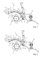
- a rear tiller 1, 1a serving as a tilling device after the Fig. 1 to 12 is provided as a rear attachment to a snow groomer, which is provided in a generally known manner for snow shoe design and - care.
- the rear tiller 1, 1a is releasably attachable to a rear carrier assembly of the snow groomer. All hydraulic drive means of the rear tiller 1, 1a are fed by a vehicle hydraulics of the snowcat and controlled by the vehicle.
- the rear tiller 1, 1a serves to break up, crush and smooth the lumpy surface of the snowpiste caused by a left and a right track drive of the snowcat.
- the rear tiller has a smoothing device 5, 10; 5, 10a, which - seen in the normal processing and direction of travel of the snowcat - at the rear of a milling housing 2, 2a of the rear tiller 1, 1a connects.
- the rear tiller 1, 1a on a milling housing which is formed of two housing sections, each extending over half of the working width of the rear tiller 1, 1a.
- a milling shaft 3, 3a is rotatably mounted and driven by a hydraulic motor.
- the milling shaft 3, 3a extends substantially over a working width of the associated housing portion.
- the two juxtaposed housing sections of the milling housing 2, 2a are rigidly coupled together in the operating state.
- a corresponding hydraulic drive is provided between the two housing sections in order to drive the two milling shafts 3, 3a extending from the center to opposite sides.
- the smoothing device has in both embodiments according to the Fig. 1 and 2 or according to the Fig. 3 to 12 a flexible smoothing structure in the form of a finisher arrangement 5, 5a, which can be pressurized from above with a plurality of carrier arrangements 10, 10a connected to a frame of the milling housing 2, 2a.
- a rear finisher of the finisher assembly 5, 5a extends over one entire working width of the milling housing 2, 2a and thus in one piece and continuously over the mutually coupled housing sections of the milling housing.
- the finisher assembly also has unspecified side finisher, of which a left side finisher in Fig. 5 is recognizable. Only difference between the two embodiments, as based on the Fig. 1 and 2 and on the basis of
- the tail finisher engages a stationary housing shell section 2 of the milling housing.
- the tail finisher of the finisher assembly 5a adjoins a displaceable housing shell section 2'a of the housing section of the milling housing.
- the displaceable housing casing section 2'a has a dovetailed carrier profile 4a, 11, in which a front end face of the rear finisher is held in a form-fitting manner.
- the two housing sections of the milling housing which are arranged side by side over the working width of the milling housing, are designed identical to one another. The following is therefore based on the FIG. 5 to 12 only one of the two housing sections described. For the other, not shown housing section the same applies.
- the housing section according to the Fig. 3 to 6 has a stationary housing shell portion 2a, which is fixedly connected to a milling frame T of the rear tiller.
- the housing shell portion 2a has at its opposite end faces on the front side housing terminations, one of which in Fig. 9 is denoted by S.
- the front-side housing terminations S serve for mounting the milling shaft 3a.
- the front-side housing terminations S are firmly connected to the stationary housing shell portion 2a.
- the stationary housing shell portion 2a is curved in a circular arc in cross section.
- the circular arc-like curvature extends in the circumferential direction of the housing section - based on a housing longitudinal axis, which extends in the vehicle transverse direction and is aligned parallel to a rotational axis of the milling shaft 3a.
- a central axis of the arcuate curvature of the housing shell portion 2a is not identical to the axis of rotation of the milling shaft 3a. In this way, a defined between the milling shaft 3a and an inner wall of the housing shell portion 2a baffle in a clockwise direction in accordance with 3 and 4 gradually rejuvenated.
- stationary housing shell portion 2a extends over an angle of more than 90 °, and preferably less than 130 °.
- a displaceable housing shell portion 2'a is additionally mounted, which in Fig. 4 in an upper end position and in Fig. 3 is shown in a lower end position.
- the displaceable housing shell section 2'a takes place on the back side of the milling housing, ie on the side of the milling housing facing the smoothing device.
- the displaceable and therefore movable housing shell portion 2'a has a dimensionally stable support profile made of metal, preferably made of steel, which extends over an entire working width of the illustrated housing portion of the milling housing.
- the carrier profile 4 has a dovetail-like profile receptacle 11, in which - as already described - a front end edge of the Heckfinishers is held positively.
- the carrier profile 4a extends parallel to a rear longitudinal edge of the stationary housing shell section 2a and is arranged substantially in alignment with the stationary housing jacket section 2a.
- the stationary housing casing section 2a has a rear-side and a front-side stiffening profile 9a, which likewise extends over the entire working width of the stationary casing casing section 2a, as does the carrier profile 4a.
- the stiffening profiles 9a and the stationary housing shell portion 2a are made of metal.
- the carrier profile 4a is held in a fan-like manner on the stationary housing casing section 2a by means of a plurality of guide arrangements 8a.
- the guide arrangements 8a are formed on the one hand by guide profiles 17 fastened on the outer circumference of the housing shell section 2a, which extend in the manner of a rail in the circumferential direction over the housing shell section 2a ( Fig. 6 ).
- These guide profiles 17 form guide grooves for guide runners 16, which protrude from the carrier profile 4a in a circular arc shape parallel to each other in the circumferential direction to the front and upward ( Fig. 11 ).
- the guide runners 16 also belong to the guide arrangements 8a and have core sections 19 and 22 made of metal, the lower core sections 22 being fastened to the support profile 4a.
- Each core section 22, 19 of a guide skid is flanked on both sides by skid sections 23 made of a low-plastic material Coefficient of sliding friction. These serve to facilitate the displacement of the guide rails 16 in the guide profiles 17.
- a cross-sectionally arcuate and therefore bowl-shaped wall 15 obliquely upwards and forwards, which is arranged uniformly at a distance radially within the guide skids 16.
- the wall 15 is in the assembled state within the milling housing on the inside to an inner wall of the stationary housing shell portion 2a nestled ( Fig. 7 to 9 ).
- front-side housing terminations S of the stationary housing shell section arcuate guide webs 20 are attached ( Fig. 7 to 9 ), which are arranged at a small, parallel distance from the inner wall of the stationary housing shell portion 2a.
- the distance of the guide webs 20 to the housing inner wall of the stationary housing shell section 2a is selected such that the shell-shaped wall 15 is guided with its opposite side edge regions in a guide gap defined between the guide webs 20 and the housing inner wall. As a result, a secure guidance of the opposite side edges of the wall 15 is achieved.
- the carrier profile 4a also has a side wall 12, which by means of an arcuate slotted guide 13 on the outside of the front-side housing closure S (FIG. Fig. 6 ) of the stationary housing shell portion is guided. For this purpose, a sliding block-like guide pin 14 is attached to the end-side housing closure S.
- a secure nestling of the wall 15 to the inner wall of the stationary housing shell portion 2a are, as shown in the Fig. 10 can be seen, provided in the baffle of the housing shell portion 2a a total of four longitudinal slots 22 which penetrate the housing shell section from inside to outside.
- the longitudinal slots 22 protrudes a screw-shaped or pin-shaped securing element 21, which penetrates the wall 15 from an inner side and is secured in a receiving bore 18 of the core element 19.
- the securing element 21 is designed as a screw provided with a screw head and the receiving bore 18 is designed as a corresponding threaded bore.
- the length of the longitudinal slot 22 preferably corresponds to the length of the slotted guide 13.
- the longitudinal slots 22 and the slotted guide 13 thus limit the displacement of the movable housing shell portion 2'a including its wall 15, its support profile 4a and its guide skids 16. Securing the wall 15 of a At the same time, the inside of the corresponding guide runners 16 also ensures that the guide runners 16 can not lift off from the guide profiles 17 of the stationary housing jacket section.
- the wall 15 is made of plastic, which may preferably have a sound insulation function. Based on FIGS. 7 and 8 It can be seen that the wall 15 completely overlaps an inner wall of the stationary housing shell section 2a in an upper end position of the movable housing shell section 2'a. In a lower end position ( Fig. 8 ), however, the wall 15 relative to the inner wall of the stationary housing shell portion 2 a fan-like down, which increases the usable for the cutter housing housing wall by the corresponding shifted angular amount instead of a baffle over a circumference of preferably about 110 ° thus becomes a baffle over a circumference generated by about 130 °.
- a displacement of the movable housing shell portion 2'a and thus the wall 15 by means of drive which according to the illustration of the Fig. 3 to 5 a hydraulic cylinder 7a include.
- the control is preferably carried out by the snowcat.
- one or more hydraulic cylinders 7a may be distributed over the working width.
Landscapes
- Engineering & Computer Science (AREA)
- Life Sciences & Earth Sciences (AREA)
- Architecture (AREA)
- Civil Engineering (AREA)
- Structural Engineering (AREA)
- Mechanical Engineering (AREA)
- Soil Sciences (AREA)
- Environmental Sciences (AREA)
- Soil Working Implements (AREA)
Applications Claiming Priority (1)
| Application Number | Priority Date | Filing Date | Title |
|---|---|---|---|
| DE102009060481A DE102009060481B4 (de) | 2009-12-18 | 2009-12-18 | Heckfräse für eine Pistenraupe zur Schneepistengestaltung und -pflege |
Publications (3)
| Publication Number | Publication Date |
|---|---|
| EP2339072A2 true EP2339072A2 (fr) | 2011-06-29 |
| EP2339072A3 EP2339072A3 (fr) | 2013-07-03 |
| EP2339072B1 EP2339072B1 (fr) | 2017-03-15 |
Family
ID=43769108
Family Applications (1)
| Application Number | Title | Priority Date | Filing Date |
|---|---|---|---|
| EP10195458.4A Active EP2339072B1 (fr) | 2009-12-18 | 2010-12-16 | Fraise arrière pour dameuse à neige |
Country Status (4)
| Country | Link |
|---|---|
| US (1) | US8646542B2 (fr) |
| EP (1) | EP2339072B1 (fr) |
| CA (1) | CA2725892C (fr) |
| DE (1) | DE102009060481B4 (fr) |
Cited By (2)
| Publication number | Priority date | Publication date | Assignee | Title |
|---|---|---|---|---|
| CN104813763A (zh) * | 2015-05-21 | 2015-08-05 | 寿县茂友农机服务专业合作社 | 一种农业用犁耙 |
| EP4217543B1 (fr) | 2020-09-24 | 2025-11-05 | PRINOTH S.p.A. | Dameuse et procédé de commande d'une dameuse |
Families Citing this family (12)
| Publication number | Priority date | Publication date | Assignee | Title |
|---|---|---|---|---|
| IN2014KN00758A (fr) * | 2011-09-05 | 2015-10-02 | Soilkee Pty Ltd | |
| JP6646951B2 (ja) * | 2015-06-08 | 2020-02-14 | 松山株式会社 | 農作業機 |
| US10231371B2 (en) * | 2016-07-18 | 2019-03-19 | Tribine Industries Llc | Soil compaction mitigation assembly and method |
| IT201800003000A1 (it) * | 2018-02-23 | 2019-08-23 | Prinoth Spa | Fresa da neve e relativo metodo di regolazione |
| IT201900024811A1 (it) * | 2019-12-19 | 2021-06-19 | Prinoth Spa | Veicolo cingolato per la rifinitura del terreno con un gruppo di lavoro sollevabile, in particolare un veicolo battipista con un gruppo fresa sollevabile |
| DE102020215732A1 (de) | 2020-12-11 | 2022-06-15 | Kässbohrer Geländefahrzeug Aktiengesellschaft | Heckfräse für eine Pistenraupe |
| US20220279712A1 (en) * | 2021-03-03 | 2022-09-08 | Fecon, Llc | Apparatus for land clearing and preparation having interchangeable chamber inserts |
| IT202100029603A1 (it) * | 2021-11-23 | 2023-05-23 | Prinoth Spa | Dente da neve per una fresa da neve e detta fresa da neve per la preparazione del manto nevoso delle piste da sci |
| IT202200020937A1 (it) * | 2022-10-11 | 2024-04-11 | Valentini Antonio S R L | Macchina agricola per la lavorazione del terreno |
| CN117468310A (zh) * | 2023-12-25 | 2024-01-30 | 德州迈隆公路工程有限公司 | 一种道路伸缩缝施工用切割装置 |
| DE202024102482U1 (de) * | 2024-05-14 | 2025-08-18 | Grimme Landmaschinenfabrik Gmbh & Co. Kg | Landwirtschaftliche Arbeitsmaschine |
| DE102024123330B4 (de) * | 2024-08-15 | 2026-03-26 | Kässbohrer Geländefahrzeug Aktiengesellschaft | Heckfräse zur Schneeflächenbearbeitung |
Family Cites Families (14)
| Publication number | Priority date | Publication date | Assignee | Title |
|---|---|---|---|---|
| US1435766A (en) * | 1918-06-05 | 1922-11-14 | Hiram H Varland | Manure spreader |
| US2805611A (en) * | 1951-05-28 | 1957-09-10 | Cleo L Fletchall | Power driven hand cultivator |
| US3011793A (en) * | 1959-02-19 | 1961-12-05 | Lowell Rudolph L | Material spreading and loading apparatus with flail beater and cover |
| US3768572A (en) * | 1972-01-21 | 1973-10-30 | Hesston Corp | Structure for eliminating mud collections in farm implements |
| NL7702108A (nl) * | 1977-02-28 | 1978-08-30 | Lely Nv C Van Der | Grondbewerkingsmachine. |
| US4204714A (en) * | 1978-04-10 | 1980-05-27 | Crafco, Inc. | Pavement cutting machine with pad to stabilize and brake machine |
| GB8331266D0 (en) * | 1983-11-23 | 1983-12-29 | Bowmer & Kirkland Products Sal | Road milling/cutting machine |
| JPH01171401A (ja) * | 1987-12-25 | 1989-07-06 | Iseki & Co Ltd | 耕耘カバー |
| US5373902A (en) * | 1993-08-30 | 1994-12-20 | Caterpillar Paving Products Inc. | Tiltable hood assembly for an earth working machine |
| JP2934200B2 (ja) * | 1997-02-14 | 1999-08-16 | ヤンマー農機株式会社 | 耕耘機におけるリヤカバー |
| JP2003180107A (ja) | 2001-12-18 | 2003-07-02 | Orec Co Ltd | 耕耘機のディファレンシャルギヤの自動制御装置及びそれを備えた耕耘機及び耕耘機の走行制御方法 |
| DE202004006301U1 (de) * | 2004-04-16 | 2004-07-22 | Kässbohrer Geländefahrzeug AG | Fräsvorrichtung für ein Fahrzeug |
| FR2886205B1 (fr) * | 2005-05-24 | 2009-06-12 | Sidel Sas | Element de rail de convoyage d'objets en position suspendue et dispositif d'alimentation comprenant un tel element |
| ITMI20070565A1 (it) * | 2007-03-21 | 2008-09-22 | Prinoth Spa | Fresa per la preparazione del manto nevoso delle piste da sci |
-
2009
- 2009-12-18 DE DE102009060481A patent/DE102009060481B4/de not_active Expired - Fee Related
-
2010
- 2010-12-15 US US12/928,619 patent/US8646542B2/en active Active
- 2010-12-16 EP EP10195458.4A patent/EP2339072B1/fr active Active
- 2010-12-16 CA CA2725892A patent/CA2725892C/fr active Active
Non-Patent Citations (1)
| Title |
|---|
| None |
Cited By (2)
| Publication number | Priority date | Publication date | Assignee | Title |
|---|---|---|---|---|
| CN104813763A (zh) * | 2015-05-21 | 2015-08-05 | 寿县茂友农机服务专业合作社 | 一种农业用犁耙 |
| EP4217543B1 (fr) | 2020-09-24 | 2025-11-05 | PRINOTH S.p.A. | Dameuse et procédé de commande d'une dameuse |
Also Published As
| Publication number | Publication date |
|---|---|
| EP2339072B1 (fr) | 2017-03-15 |
| US20110147019A1 (en) | 2011-06-23 |
| DE102009060481A1 (de) | 2011-06-22 |
| US8646542B2 (en) | 2014-02-11 |
| CA2725892A1 (fr) | 2011-06-18 |
| DE102009060481B4 (de) | 2012-10-04 |
| EP2339072A3 (fr) | 2013-07-03 |
| CA2725892C (fr) | 2017-11-28 |
Similar Documents
| Publication | Publication Date | Title |
|---|---|---|
| EP2339072B1 (fr) | Fraise arrière pour dameuse à neige | |
| DE4101617C2 (de) | Planiergerät für Schneeflächen und Verfahren zur Aufbereitung und/oder Pflege einer Schneefläche | |
| EP2374937B1 (fr) | Engin de traitement d'une surface de voie de circulation | |
| DE102010050831A1 (de) | Rotorhaube für eine Fräsvorrichtung | |
| WO2018146263A1 (fr) | Dispositif de labourage muni de deux éléments de coupe | |
| DE3025312A1 (de) | Spur- oder planiergeraet fuer ski-loipen bzw. pisten | |
| EP3557977B1 (fr) | Appareil de coupe sous-jacente de mottes racinaires et de déterrage | |
| DE102012018918A1 (de) | Abstreifvorrichtung für Fräswalzen einer Baumaschine und Baumaschine | |
| DE2629284C3 (de) | Fräsmaschine zur Bankett-, Graben- und Böschungsreinigung | |
| EP2842413A1 (fr) | Élément de soutien et/ou de conduite de récoltes dans une moissonneuse | |
| EP2319988B1 (fr) | Engin de montage arrière pour un dameur de piste | |
| EP1925746B1 (fr) | Dispositif d'entretien de pistes pour un véhicule à chenilles | |
| DE2932695A1 (de) | Bodenbearbeitungsmaschine | |
| EP1197601B1 (fr) | Dispositif de fraisage-concassage | |
| DE202007016639U1 (de) | Reitbodenpflegegerät | |
| DE69616091T2 (de) | Zinkenblatt, insbesondere für zinkenträger | |
| DE4431551C2 (de) | Brecher mit einem Gestell, in dem ein angetriebener, steinbrechender Rotor gelagert ist | |
| EP0161621A2 (fr) | Machine pour le travail du sol | |
| EP0964961A1 (fr) | Dispositif de damage des pistes | |
| DE102024123330B4 (de) | Heckfräse zur Schneeflächenbearbeitung | |
| EP0718586A1 (fr) | Dispositif pour travailler la terre | |
| AT505831B1 (de) | Loipenspurgerät | |
| DE930715C (de) | Vorrichtung zum Reinigen und Offenhalten von Graeben, insbesondere Entwaesserungsgraeben | |
| DE2803502A1 (de) | Motorisch antreibbare fraestrommel zur boeschungs- und grabenbearbeitung | |
| DE10333423A1 (de) | Pistenpflegevorrichtung |
Legal Events
| Date | Code | Title | Description |
|---|---|---|---|
| PUAI | Public reference made under article 153(3) epc to a published international application that has entered the european phase |
Free format text: ORIGINAL CODE: 0009012 |
|
| AK | Designated contracting states |
Kind code of ref document: A2 Designated state(s): AL AT BE BG CH CY CZ DE DK EE ES FI FR GB GR HR HU IE IS IT LI LT LU LV MC MK MT NL NO PL PT RO RS SE SI SK SM TR |
|
| AX | Request for extension of the european patent |
Extension state: BA ME |
|
| REG | Reference to a national code |
Ref country code: DE Ref legal event code: R079 Ref document number: 502010013303 Country of ref document: DE Free format text: PREVIOUS MAIN CLASS: E01H0005000000 Ipc: E01H0004020000 |
|
| PUAL | Search report despatched |
Free format text: ORIGINAL CODE: 0009013 |
|
| AK | Designated contracting states |
Kind code of ref document: A3 Designated state(s): AL AT BE BG CH CY CZ DE DK EE ES FI FR GB GR HR HU IE IS IT LI LT LU LV MC MK MT NL NO PL PT RO RS SE SI SK SM TR |
|
| AX | Request for extension of the european patent |
Extension state: BA ME |
|
| RIC1 | Information provided on ipc code assigned before grant |
Ipc: E01H 4/02 20060101AFI20130528BHEP Ipc: A01B 33/02 20060101ALI20130528BHEP |
|
| 17P | Request for examination filed |
Effective date: 20131127 |
|
| RBV | Designated contracting states (corrected) |
Designated state(s): AL AT BE BG CH CY CZ DE DK EE ES FI FR GB GR HR HU IE IS IT LI LT LU LV MC MK MT NL NO PL PT RO RS SE SI SK SM TR |
|
| GRAP | Despatch of communication of intention to grant a patent |
Free format text: ORIGINAL CODE: EPIDOSNIGR1 |
|
| INTG | Intention to grant announced |
Effective date: 20161104 |
|
| GRAS | Grant fee paid |
Free format text: ORIGINAL CODE: EPIDOSNIGR3 |
|
| GRAA | (expected) grant |
Free format text: ORIGINAL CODE: 0009210 |
|
| AK | Designated contracting states |
Kind code of ref document: B1 Designated state(s): AL AT BE BG CH CY CZ DE DK EE ES FI FR GB GR HR HU IE IS IT LI LT LU LV MC MK MT NL NO PL PT RO RS SE SI SK SM TR |
|
| REG | Reference to a national code |
Ref country code: CH Ref legal event code: EP Ref country code: GB Ref legal event code: FG4D Free format text: NOT ENGLISH |
|
| REG | Reference to a national code |
Ref country code: IE Ref legal event code: FG4D Free format text: LANGUAGE OF EP DOCUMENT: GERMAN |
|
| REG | Reference to a national code |
Ref country code: CH Ref legal event code: NV Representative=s name: DR. LUSUARDI AG, CH |
|
| REG | Reference to a national code |
Ref country code: AT Ref legal event code: REF Ref document number: 875712 Country of ref document: AT Kind code of ref document: T Effective date: 20170415 |
|
| REG | Reference to a national code |
Ref country code: DE Ref legal event code: R096 Ref document number: 502010013303 Country of ref document: DE |
|
| REG | Reference to a national code |
Ref country code: NL Ref legal event code: MP Effective date: 20170315 |
|
| REG | Reference to a national code |
Ref country code: LT Ref legal event code: MG4D |
|
| PG25 | Lapsed in a contracting state [announced via postgrant information from national office to epo] |
Ref country code: LT Free format text: LAPSE BECAUSE OF FAILURE TO SUBMIT A TRANSLATION OF THE DESCRIPTION OR TO PAY THE FEE WITHIN THE PRESCRIBED TIME-LIMIT Effective date: 20170315 Ref country code: NO Free format text: LAPSE BECAUSE OF FAILURE TO SUBMIT A TRANSLATION OF THE DESCRIPTION OR TO PAY THE FEE WITHIN THE PRESCRIBED TIME-LIMIT Effective date: 20170615 Ref country code: HR Free format text: LAPSE BECAUSE OF FAILURE TO SUBMIT A TRANSLATION OF THE DESCRIPTION OR TO PAY THE FEE WITHIN THE PRESCRIBED TIME-LIMIT Effective date: 20170315 Ref country code: FI Free format text: LAPSE BECAUSE OF FAILURE TO SUBMIT A TRANSLATION OF THE DESCRIPTION OR TO PAY THE FEE WITHIN THE PRESCRIBED TIME-LIMIT Effective date: 20170315 Ref country code: GR Free format text: LAPSE BECAUSE OF FAILURE TO SUBMIT A TRANSLATION OF THE DESCRIPTION OR TO PAY THE FEE WITHIN THE PRESCRIBED TIME-LIMIT Effective date: 20170616 |
|
| PG25 | Lapsed in a contracting state [announced via postgrant information from national office to epo] |
Ref country code: RS Free format text: LAPSE BECAUSE OF FAILURE TO SUBMIT A TRANSLATION OF THE DESCRIPTION OR TO PAY THE FEE WITHIN THE PRESCRIBED TIME-LIMIT Effective date: 20170315 Ref country code: SE Free format text: LAPSE BECAUSE OF FAILURE TO SUBMIT A TRANSLATION OF THE DESCRIPTION OR TO PAY THE FEE WITHIN THE PRESCRIBED TIME-LIMIT Effective date: 20170315 Ref country code: LV Free format text: LAPSE BECAUSE OF FAILURE TO SUBMIT A TRANSLATION OF THE DESCRIPTION OR TO PAY THE FEE WITHIN THE PRESCRIBED TIME-LIMIT Effective date: 20170315 Ref country code: BG Free format text: LAPSE BECAUSE OF FAILURE TO SUBMIT A TRANSLATION OF THE DESCRIPTION OR TO PAY THE FEE WITHIN THE PRESCRIBED TIME-LIMIT Effective date: 20170615 |
|
| PG25 | Lapsed in a contracting state [announced via postgrant information from national office to epo] |
Ref country code: NL Free format text: LAPSE BECAUSE OF FAILURE TO SUBMIT A TRANSLATION OF THE DESCRIPTION OR TO PAY THE FEE WITHIN THE PRESCRIBED TIME-LIMIT Effective date: 20170315 |
|
| PG25 | Lapsed in a contracting state [announced via postgrant information from national office to epo] |
Ref country code: RO Free format text: LAPSE BECAUSE OF FAILURE TO SUBMIT A TRANSLATION OF THE DESCRIPTION OR TO PAY THE FEE WITHIN THE PRESCRIBED TIME-LIMIT Effective date: 20170315 Ref country code: SK Free format text: LAPSE BECAUSE OF FAILURE TO SUBMIT A TRANSLATION OF THE DESCRIPTION OR TO PAY THE FEE WITHIN THE PRESCRIBED TIME-LIMIT Effective date: 20170315 Ref country code: ES Free format text: LAPSE BECAUSE OF FAILURE TO SUBMIT A TRANSLATION OF THE DESCRIPTION OR TO PAY THE FEE WITHIN THE PRESCRIBED TIME-LIMIT Effective date: 20170315 Ref country code: EE Free format text: LAPSE BECAUSE OF FAILURE TO SUBMIT A TRANSLATION OF THE DESCRIPTION OR TO PAY THE FEE WITHIN THE PRESCRIBED TIME-LIMIT Effective date: 20170315 Ref country code: CZ Free format text: LAPSE BECAUSE OF FAILURE TO SUBMIT A TRANSLATION OF THE DESCRIPTION OR TO PAY THE FEE WITHIN THE PRESCRIBED TIME-LIMIT Effective date: 20170315 |
|
| PG25 | Lapsed in a contracting state [announced via postgrant information from national office to epo] |
Ref country code: PT Free format text: LAPSE BECAUSE OF FAILURE TO SUBMIT A TRANSLATION OF THE DESCRIPTION OR TO PAY THE FEE WITHIN THE PRESCRIBED TIME-LIMIT Effective date: 20170717 Ref country code: PL Free format text: LAPSE BECAUSE OF FAILURE TO SUBMIT A TRANSLATION OF THE DESCRIPTION OR TO PAY THE FEE WITHIN THE PRESCRIBED TIME-LIMIT Effective date: 20170315 Ref country code: IS Free format text: LAPSE BECAUSE OF FAILURE TO SUBMIT A TRANSLATION OF THE DESCRIPTION OR TO PAY THE FEE WITHIN THE PRESCRIBED TIME-LIMIT Effective date: 20170715 Ref country code: SM Free format text: LAPSE BECAUSE OF FAILURE TO SUBMIT A TRANSLATION OF THE DESCRIPTION OR TO PAY THE FEE WITHIN THE PRESCRIBED TIME-LIMIT Effective date: 20170315 |
|
| REG | Reference to a national code |
Ref country code: DE Ref legal event code: R097 Ref document number: 502010013303 Country of ref document: DE |
|
| REG | Reference to a national code |
Ref country code: FR Ref legal event code: PLFP Year of fee payment: 8 |
|
| PLBE | No opposition filed within time limit |
Free format text: ORIGINAL CODE: 0009261 |
|
| STAA | Information on the status of an ep patent application or granted ep patent |
Free format text: STATUS: NO OPPOSITION FILED WITHIN TIME LIMIT |
|
| PG25 | Lapsed in a contracting state [announced via postgrant information from national office to epo] |
Ref country code: DK Free format text: LAPSE BECAUSE OF FAILURE TO SUBMIT A TRANSLATION OF THE DESCRIPTION OR TO PAY THE FEE WITHIN THE PRESCRIBED TIME-LIMIT Effective date: 20170315 |
|
| 26N | No opposition filed |
Effective date: 20171218 |
|
| PG25 | Lapsed in a contracting state [announced via postgrant information from national office to epo] |
Ref country code: SI Free format text: LAPSE BECAUSE OF FAILURE TO SUBMIT A TRANSLATION OF THE DESCRIPTION OR TO PAY THE FEE WITHIN THE PRESCRIBED TIME-LIMIT Effective date: 20170315 |
|
| GBPC | Gb: european patent ceased through non-payment of renewal fee |
Effective date: 20171216 |
|
| REG | Reference to a national code |
Ref country code: IE Ref legal event code: MM4A |
|
| PG25 | Lapsed in a contracting state [announced via postgrant information from national office to epo] |
Ref country code: MT Free format text: LAPSE BECAUSE OF FAILURE TO SUBMIT A TRANSLATION OF THE DESCRIPTION OR TO PAY THE FEE WITHIN THE PRESCRIBED TIME-LIMIT Effective date: 20170315 Ref country code: LU Free format text: LAPSE BECAUSE OF NON-PAYMENT OF DUE FEES Effective date: 20171216 |
|
| REG | Reference to a national code |
Ref country code: BE Ref legal event code: MM Effective date: 20171231 |
|
| PG25 | Lapsed in a contracting state [announced via postgrant information from national office to epo] |
Ref country code: IE Free format text: LAPSE BECAUSE OF NON-PAYMENT OF DUE FEES Effective date: 20171216 |
|
| PG25 | Lapsed in a contracting state [announced via postgrant information from national office to epo] |
Ref country code: BE Free format text: LAPSE BECAUSE OF NON-PAYMENT OF DUE FEES Effective date: 20171231 Ref country code: GB Free format text: LAPSE BECAUSE OF NON-PAYMENT OF DUE FEES Effective date: 20171216 |
|
| PG25 | Lapsed in a contracting state [announced via postgrant information from national office to epo] |
Ref country code: HU Free format text: LAPSE BECAUSE OF FAILURE TO SUBMIT A TRANSLATION OF THE DESCRIPTION OR TO PAY THE FEE WITHIN THE PRESCRIBED TIME-LIMIT; INVALID AB INITIO Effective date: 20101216 Ref country code: MC Free format text: LAPSE BECAUSE OF FAILURE TO SUBMIT A TRANSLATION OF THE DESCRIPTION OR TO PAY THE FEE WITHIN THE PRESCRIBED TIME-LIMIT Effective date: 20170315 |
|
| PG25 | Lapsed in a contracting state [announced via postgrant information from national office to epo] |
Ref country code: CY Free format text: LAPSE BECAUSE OF NON-PAYMENT OF DUE FEES Effective date: 20170315 |
|
| PG25 | Lapsed in a contracting state [announced via postgrant information from national office to epo] |
Ref country code: MK Free format text: LAPSE BECAUSE OF FAILURE TO SUBMIT A TRANSLATION OF THE DESCRIPTION OR TO PAY THE FEE WITHIN THE PRESCRIBED TIME-LIMIT Effective date: 20170315 |
|
| PG25 | Lapsed in a contracting state [announced via postgrant information from national office to epo] |
Ref country code: TR Free format text: LAPSE BECAUSE OF FAILURE TO SUBMIT A TRANSLATION OF THE DESCRIPTION OR TO PAY THE FEE WITHIN THE PRESCRIBED TIME-LIMIT Effective date: 20170315 |
|
| PG25 | Lapsed in a contracting state [announced via postgrant information from national office to epo] |
Ref country code: AL Free format text: LAPSE BECAUSE OF FAILURE TO SUBMIT A TRANSLATION OF THE DESCRIPTION OR TO PAY THE FEE WITHIN THE PRESCRIBED TIME-LIMIT Effective date: 20170315 |
|
| REG | Reference to a national code |
Ref country code: CH Ref legal event code: U11 Free format text: ST27 STATUS EVENT CODE: U-0-0-U10-U11 (AS PROVIDED BY THE NATIONAL OFFICE) Effective date: 20260101 |
|
| PGFP | Annual fee paid to national office [announced via postgrant information from national office to epo] |
Ref country code: DE Payment date: 20251217 Year of fee payment: 16 |
|
| PGFP | Annual fee paid to national office [announced via postgrant information from national office to epo] |
Ref country code: AT Payment date: 20251215 Year of fee payment: 16 |
|
| PGFP | Annual fee paid to national office [announced via postgrant information from national office to epo] |
Ref country code: FR Payment date: 20251218 Year of fee payment: 16 |
|
| PGFP | Annual fee paid to national office [announced via postgrant information from national office to epo] |
Ref country code: IT Payment date: 20251231 Year of fee payment: 16 |
|
| PGFP | Annual fee paid to national office [announced via postgrant information from national office to epo] |
Ref country code: CH Payment date: 20260101 Year of fee payment: 16 |