EP2339700A1 - Connecteur, douille de connecteur et raccordement enfichable pour un appareil auditif - Google Patents
Connecteur, douille de connecteur et raccordement enfichable pour un appareil auditif Download PDFInfo
- Publication number
- EP2339700A1 EP2339700A1 EP10015972A EP10015972A EP2339700A1 EP 2339700 A1 EP2339700 A1 EP 2339700A1 EP 10015972 A EP10015972 A EP 10015972A EP 10015972 A EP10015972 A EP 10015972A EP 2339700 A1 EP2339700 A1 EP 2339700A1
- Authority
- EP
- European Patent Office
- Prior art keywords
- connector
- tubular housing
- contact
- connector socket
- rotatable sleeve
- Prior art date
- Legal status (The legal status is an assumption and is not a legal conclusion. Google has not performed a legal analysis and makes no representation as to the accuracy of the status listed.)
- Granted
Links
Images




Classifications
-
- H—ELECTRICITY
- H01—ELECTRIC ELEMENTS
- H01R—ELECTRICALLY-CONDUCTIVE CONNECTIONS; STRUCTURAL ASSOCIATIONS OF A PLURALITY OF MUTUALLY-INSULATED ELECTRICAL CONNECTING ELEMENTS; COUPLING DEVICES; CURRENT COLLECTORS
- H01R13/00—Details of coupling devices of the kinds covered by groups H01R12/70 or H01R24/00 - H01R33/00
- H01R13/62—Means for facilitating engagement or disengagement of coupling parts or for holding them in engagement
- H01R13/625—Casing or ring with bayonet engagement
-
- H—ELECTRICITY
- H01—ELECTRIC ELEMENTS
- H01R—ELECTRICALLY-CONDUCTIVE CONNECTIONS; STRUCTURAL ASSOCIATIONS OF A PLURALITY OF MUTUALLY-INSULATED ELECTRICAL CONNECTING ELEMENTS; COUPLING DEVICES; CURRENT COLLECTORS
- H01R13/00—Details of coupling devices of the kinds covered by groups H01R12/70 or H01R24/00 - H01R33/00
- H01R13/62—Means for facilitating engagement or disengagement of coupling parts or for holding them in engagement
- H01R13/622—Screw-ring or screw-casing
-
- H—ELECTRICITY
- H04—ELECTRIC COMMUNICATION TECHNIQUE
- H04R—LOUDSPEAKERS, MICROPHONES, GRAMOPHONE PICK-UPS OR LIKE ACOUSTIC ELECTROMECHANICAL TRANSDUCERS; ELECTRIC HEARING AIDS; PUBLIC ADDRESS SYSTEMS
- H04R25/00—Electric hearing aids
- H04R25/65—Housing parts, e.g. shells, tips or moulds, or their manufacture
-
- H—ELECTRICITY
- H01—ELECTRIC ELEMENTS
- H01R—ELECTRICALLY-CONDUCTIVE CONNECTIONS; STRUCTURAL ASSOCIATIONS OF A PLURALITY OF MUTUALLY-INSULATED ELECTRICAL CONNECTING ELEMENTS; COUPLING DEVICES; CURRENT COLLECTORS
- H01R2201/00—Connectors or connections adapted for particular applications
- H01R2201/12—Connectors or connections adapted for particular applications for medicine and surgery
-
- H—ELECTRICITY
- H04—ELECTRIC COMMUNICATION TECHNIQUE
- H04R—LOUDSPEAKERS, MICROPHONES, GRAMOPHONE PICK-UPS OR LIKE ACOUSTIC ELECTROMECHANICAL TRANSDUCERS; ELECTRIC HEARING AIDS; PUBLIC ADDRESS SYSTEMS
- H04R25/00—Electric hearing aids
- H04R25/60—Mounting or interconnection of hearing aid parts, e.g. inside tips, housings or to ossicles
- H04R25/607—Mounting or interconnection of hearing aid parts, e.g. inside tips, housings or to ossicles of earhooks
Definitions
- the present invention relates to a plug connection for a hearing device, that is, a connector and an associated connector socket for connecting a cable to a hearing aid, in particular a hearing aid to be worn behind the ear (HDO).
- a plug connection for a hearing device that is, a connector and an associated connector socket for connecting a cable to a hearing aid, in particular a hearing aid to be worn behind the ear (HDO).
- a hearing aid is provided with at least one audio port to feed an electrical signal from a radio, television or the like into the hearing aid. Furthermore, the hearing aid may possibly be programmable via a fed signal. Because the associated audio or programming cable is not intended to be permanently attached to the hearing aid, a plug is required to release the cable from the hearing aid. Such a plug should ensure a secure contact even under difficult conditions such as high humidity, etc.
- the object of the invention is thus to provide a connector and an associated connector socket for connecting a cable to a hearing aid, which allow secure contact even under difficult conditions. Furthermore, a high number of cycles should be achieved over a long period of time with the connector and the connector socket.
- At least one contact disposed in an interior, in particular on an inner circumference of the tubular housing; and a rotatable sleeve disposed on an outer circumference of the tubular housing and rotatable relative to the tubular housing by at least a predetermined angle and having engaging means for engaging a complementary connector sleeve.
- the contact is arranged in the interior, in particular on an inner circumference of the tubular housing, while the rotatable sleeve has the engagement means, the contacting on the one hand and the fixation on the other hand is fulfilled by different components. Since the rotatable sleeve is rotatably mounted relative to the contacts, the secure contacting of the contact is not affected by the fixing or fastening or engaging means. In addition, a wear of the contact is reduced because during the fixation no grinding of the contact occurs.
- the engagement means comprises a pair of protrusions disposed on an outer or inner periphery of the rotatable sleeve.
- the engagement means preferably a pair of projections in the form of a bayonet closure, an excellent fixation of the connector to the complementary connector socket is ensured and at the same time a secure contact is achieved.
- the contact is formed as a leaf spring and preferably arranged parallel to a longitudinal axis of the tubular housing.
- a plurality of contacts are arranged, preferably four contacts, and the contacts are preferably arranged at substantially equal angular intervals on the inner circumference of the tubular housing.
- each contact is designed as a leaf spring.
- the rotatable sleeve has at a front portion a first sealing element for sealing against a complementary housing or a complementary connector socket and / or on an inner circumference a second sealing element for sealing with respect to the tubular housing.
- the first sealing element may be an O-ring.
- the second sealing element may be an O-ring having an outer diameter of about 2 to 5 mm, preferably 3 to 4 mm, most preferably about 3.8 mm.
- first and / or second sealing element is arranged in particular in the form of a simple O-ring, the contacting point is substantially completely sealed to the outside. Thus, even in high humidity or humid environment contacting problems can be avoided.
- the engagement means preferably has at least one guide groove, preferably a pair of guide grooves.
- the contact element is arranged in a groove of the projection, which preferably extends parallel to a longitudinal axis of the projection.
- a plurality of contact elements is arranged, in particular four contact elements may be arranged, and the contact elements are preferably arranged at substantially equal angular intervals on the outer periphery of the projection.
- Another aspect relates to a plug connection comprising the connector according to the invention and the connector socket according to the invention.
- a hearing aid 7 has a connector socket 8, which is connectable to a connector 1 to which a cable 5 is connected. In this way, a releasable electrical connection of the cable 5 with the hearing aid 7 is created.
- FIG. 2 shows a perspective view of the connector 1 and the connector socket 8, if it is not installed in the hearing aid 7.
- FIG. 2 shows FIG. 2 a plug connection for a hearing aid comprising the connector 1 and the connector socket 2.
- the plug connection is shown without hearing aid.
- the male terminal has an overall length of about 4 to 8 mm, preferably 5 to 7 mm, most preferably about 6 mm and a width of about 2 to 5 mm, preferably about 3 to 4 mm, most preferably about 3.5 mm.
- the connector socket 8 has a projection 82, on the outer circumference of contact elements 88 are arranged.
- contact elements 88 are arranged at equal angular intervals, that is to say at 90 ° intervals on the outer circumference of the projection 82.
- the invention is not limited thereto, but only one contact element 88 or two, three or more than four contact elements 88 can be arranged as required.
- the contact elements 88 are arranged in a groove 86.
- This groove 86 serves to guide the complementary connector to contacts 20 (see FIG. 3 ) to be brought into contact with the contact elements 88 of the connector socket 8.
- the contact elements 88 are protected by embedding in the groove 86 from damage such as bending.
- the connector socket 8 has engagement means 84 for engagement with engagement means 32 (see FIG. 3 ) of the complementary connector 1.
- the engagement means 84 are preferably formed as a pair of guide grooves, the is called, as a so-called bayonet lock.
- This guide groove has a groove portion extending rearwardly from a front side of the connector bush 8 along the longitudinal axis of the connector bush 8, and is adjoined by another groove portion extending substantially in the circumferential direction of the connector bush 8. In this way, a complementary engaging means 32 can be inserted into the guide groove and twisted along the circumference of the connector socket 8 to fix the complementary connector 1 to the connector socket 8.
- the connector 1 a tubular housing 10, on the inner circumference of contacts 20 are arranged.
- a tubular housing 10 on the inner circumference of contacts 20 are arranged.
- four contacts at uniform angular intervals, that is distributed at 90 ° intervals on the inner circumference of the tubular housing 10.
- only one contact 20, two, three or more than four contacts 20 can be arranged.
- the contacts 20 are preferably designed as leaf springs to elastically deform during contact with the contact elements 88 of the connector socket 8, so that the spring force ensures a secure contact.
- the leaf spring of the contacts 20 preferably has a rectangular cross-section and has a kink at a front portion to bear against the tubular housing 10. In the region of the buckling, the contacting of the contact 20 with the contact elements 88 occurs when the tubular housing 10 is inserted into the connector socket 8.
- the invention is not limited thereto. It may also be formed as a leaf spring instead of the contacts 20, the contact elements 88.
- a rotatable sleeve 30 is arranged, which is rotatably arranged at least by a predetermined angle relative to the tubular housing 10.
- a pair of projections as engagement means 32 is arranged on an outer periphery of the rotatable sleeve 30, a pair of projections as engagement means 32 is arranged. Upon insertion of the connector 1 into the connector socket 8, these engaging means 32 enter the guide groove of the engagement means 84 of the connector socket 8, and by rotating the rotatable sleeve, the connector 1 is secured to the connector socket 8.
- the rotatable sleeve 30 is further provided on an outer periphery with a sealing member 40 to seal in an inner circumference of a housing of the hearing aid 7 (or alternatively in an inner circumference of the connector socket 8). Furthermore, the rotatable sleeve 30 is preferably sealed to an inner periphery with a second sealing element 42 opposite the tubular housing 10.
- the first and second sealing elements 40, 42 are preferably made of an O-ring, in particular an O-ring of neoprene or other suitable rubber, silicone or the like. In this way, the contact point between the contacts 20 and the contact elements 88 against the environment is sealed excellent.
- a sealing element 52 for sealing the cable 5 with respect to the tubular housing 10 is preferably arranged.
- This sealing element 52 is preferably a molded part made of rubber, silicone or the like.
- the latching means 14 are preferably elastically deformable to be deformable to each other to reduce its outer circumference.
- the rotatable sleeve 30 is preferably mounted such that the locking means 14 are elastically deformed inwardly so that the rotatable sleeve 30 can be pushed onto the tubular housing 10.
- the locking means 14 are elastically reset when the rotatable sleeve 30 is fully pushed onto the tubular housing 10 and the locking means 14 secure in this way the rotatable sleeve 30 to the tubular housing 10th
- the rotatable sleeve 30 preferably has on an outer circumference a grip portion, for example, in the shape of a square. However, the invention is not limited thereto.
- the handle portion of the rotatable sleeve 30 may also have a circular shape with a corresponding knurl for good gripping or other gripping means.
- the contacts 20 are preferably connected to a strand of the cable 5 via crimping sections (not shown).
- these contact elements 88 can also be soldered or screwed to a circuit board or the like of the hearing device 7.
- the engaging means 32 are disposed on an outer circumference of the rotatable sleeve 30, they may also be disposed on an inner circumference of the rotatable sleeve 30.
- the guide groove of the engaging means 84 of the connector socket 8 may also be disposed on the connector 1 and the protrusions of the engaging means 32 of FIG rotatable sleeve 30 are arranged in this case on the connector socket 8.
- the contacts 20 can also be soldered or screwed to a strand of the cable 5 instead of being crimped.
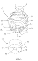
- FIG. 5 further shows a perspective detail view of the connector socket 8.
- the projection 82, the engagement means 84, the grooves 86 and the contact elements 88 are shown.
- the contact elements 88 are arranged in the corresponding grooves 86 of the projection 82 and fixed there.
- the contact elements 88 are set such that the contacts 20 can contact the respective contact elements 88 and a sufficiently high contact pressure between the contacts 20 is in each case the corresponding contact element 88, so that an electrical contact is ensured.
- the contact pressure force is about 0.5 to 2 N, preferably 0.7 to 1.5 N, most preferably about 1 N.
Landscapes
- Engineering & Computer Science (AREA)
- Manufacturing & Machinery (AREA)
- Health & Medical Sciences (AREA)
- General Health & Medical Sciences (AREA)
- Neurosurgery (AREA)
- Otolaryngology (AREA)
- Physics & Mathematics (AREA)
- Acoustics & Sound (AREA)
- Signal Processing (AREA)
- Details Of Connecting Devices For Male And Female Coupling (AREA)
- Connector Housings Or Holding Contact Members (AREA)
Applications Claiming Priority (1)
| Application Number | Priority Date | Filing Date | Title |
|---|---|---|---|
| DE102009060307A DE102009060307B4 (de) | 2009-12-23 | 2009-12-23 | Verbinderbuchse und Steckanschluß für ein Hörgerät |
Publications (2)
| Publication Number | Publication Date |
|---|---|
| EP2339700A1 true EP2339700A1 (fr) | 2011-06-29 |
| EP2339700B1 EP2339700B1 (fr) | 2014-06-25 |
Family
ID=43797614
Family Applications (1)
| Application Number | Title | Priority Date | Filing Date |
|---|---|---|---|
| EP10015972.2A Active EP2339700B1 (fr) | 2009-12-23 | 2010-12-22 | Connecteur, douille de connecteur et raccordement enfichable pour un appareil auditif |
Country Status (2)
| Country | Link |
|---|---|
| EP (1) | EP2339700B1 (fr) |
| DE (1) | DE102009060307B4 (fr) |
Families Citing this family (2)
| Publication number | Priority date | Publication date | Assignee | Title |
|---|---|---|---|---|
| FR3058927A1 (fr) | 2016-11-22 | 2018-05-25 | Compagnie Generale Des Etablissements Michelin | Bande de roulement comportant des nervures incisees |
| DE102020002379A1 (de) * | 2020-04-20 | 2021-10-21 | Yamaichi Electronics Deutschland Gmbh | Hörgerät mit einer Mikrofoneinheit und einer Lautsprechereinheit, Verbinder und Verwendung eines Verbinders zum Verbinden einer Mikrofoneinheit und einer Lautsprechereinheit eines Hörgeräts |
Citations (5)
| Publication number | Priority date | Publication date | Assignee | Title |
|---|---|---|---|---|
| CH669296A5 (en) * | 1986-05-28 | 1989-02-28 | Gfeller Ag Apparate Fabrik Fla | Electroacoustic hearing aid with contact for external equipment - has battery compartment adapted to accept plug connection from external broadcast receiver or voice communication appts. |
| DE3940230A1 (de) * | 1989-12-05 | 1991-06-06 | Siemens Nixdorf Inf Syst | Steckeranordnung fuer ein mehradriges kabel |
| US5404407A (en) * | 1992-10-07 | 1995-04-04 | Siemens Audiologische Technik Gmbh | Programmable hearing aid unit |
| DE10352159A1 (de) * | 2003-05-19 | 2004-12-30 | Endress + Hauser Conducta Gesellschaft für Mess- und Regeltechnik mbH + Co. KG | Steckverbinderkupplung |
| WO2008034134A2 (fr) * | 2006-09-15 | 2008-03-20 | Amphenol Corporation | Connecteur homologue à baïonnette haute densité |
Family Cites Families (5)
| Publication number | Priority date | Publication date | Assignee | Title |
|---|---|---|---|---|
| GB1297426A (fr) * | 1970-05-19 | 1972-11-22 | ||
| JP2910500B2 (ja) * | 1993-04-19 | 1999-06-23 | 住友電装株式会社 | 電気自動車充電用コネクタ |
| DE10244962B3 (de) * | 2002-09-26 | 2004-06-24 | Siemens Audiologische Technik Gmbh | Hörgerät mit einer externen Elektronikkomponente |
| DE102006045484B4 (de) * | 2006-09-27 | 2011-12-01 | Bruckhoff Apparatebau Gmbh | Hörgerät |
| DE102007009748A1 (de) * | 2007-02-28 | 2008-09-04 | Siemens Audiologische Technik Gmbh | Hörhilfegerät |
-
2009
- 2009-12-23 DE DE102009060307A patent/DE102009060307B4/de not_active Expired - Fee Related
-
2010
- 2010-12-22 EP EP10015972.2A patent/EP2339700B1/fr active Active
Patent Citations (5)
| Publication number | Priority date | Publication date | Assignee | Title |
|---|---|---|---|---|
| CH669296A5 (en) * | 1986-05-28 | 1989-02-28 | Gfeller Ag Apparate Fabrik Fla | Electroacoustic hearing aid with contact for external equipment - has battery compartment adapted to accept plug connection from external broadcast receiver or voice communication appts. |
| DE3940230A1 (de) * | 1989-12-05 | 1991-06-06 | Siemens Nixdorf Inf Syst | Steckeranordnung fuer ein mehradriges kabel |
| US5404407A (en) * | 1992-10-07 | 1995-04-04 | Siemens Audiologische Technik Gmbh | Programmable hearing aid unit |
| DE10352159A1 (de) * | 2003-05-19 | 2004-12-30 | Endress + Hauser Conducta Gesellschaft für Mess- und Regeltechnik mbH + Co. KG | Steckverbinderkupplung |
| WO2008034134A2 (fr) * | 2006-09-15 | 2008-03-20 | Amphenol Corporation | Connecteur homologue à baïonnette haute densité |
Also Published As
| Publication number | Publication date |
|---|---|
| DE102009060307A1 (de) | 2011-06-30 |
| EP2339700B1 (fr) | 2014-06-25 |
| DE102009060307B4 (de) | 2012-11-22 |
Similar Documents
| Publication | Publication Date | Title |
|---|---|---|
| EP3433907B1 (fr) | Connecteur comprenant un élément de connecteur complémentaire | |
| EP1355386B1 (fr) | Connecteur à fiche rond pour des câbles électriques blindés | |
| EP1926179B1 (fr) | Connecteur à fiches pour conducteurs électriques assemblés | |
| EP3639329B1 (fr) | Élément de connexion enfichable doté d'éléments de contact matés et son procédé de fabrication | |
| EP3714513A1 (fr) | Connecteur électrique et ensemble de lignes électriques équipée d'un tel connecteur électrique | |
| DE102010034789B3 (de) | Steckverbinder | |
| DE102018207598B4 (de) | Anschluss für einen runden stiftförmigen elektrischen Kontakt | |
| DE102017222809B4 (de) | Elektrischer Steckverbinder und Steckverbindung | |
| EP1467441A2 (fr) | Connecteur pour un branchement rapide à technique de pince de serrage | |
| EP3633802A1 (fr) | Prise de courant d'appareil, connecteur d'appareil et système de connecteur d'appareil | |
| DE102009060307B4 (de) | Verbinderbuchse und Steckanschluß für ein Hörgerät | |
| DE102017126185B4 (de) | Elektrisches Kontaktelement | |
| EP4416801A1 (fr) | Module de connecteur et son procédé de production | |
| DE10255190B4 (de) | Rundsteckverbindungseinheit | |
| EP2071676A2 (fr) | Agencement de connecteur | |
| EP3676918A1 (fr) | Connecteur enfichable coudé et procédé de fabrication | |
| EP2586105A1 (fr) | Connecteur enfichable | |
| DE102016100339B4 (de) | Elektrischer steckverbinder und elektrische kontaktverbindung | |
| DE202017107625U1 (de) | Elektrischer Steckverbinder | |
| DE102007018945B4 (de) | Steckbuchse für Telekommunikations- und Datenübertragungssysteme | |
| DE202012008785U1 (de) | Steckverbindung | |
| AT410614B (de) | Kabelstecker mit einem steckergehäuse und elektrischen kontaktelementen | |
| WO2013000609A1 (fr) | Connecteur avec élément de protection des torons | |
| EP3200288B1 (fr) | Boîtier de connecteur électrique ou destiné à recevoir un connecteur électrique | |
| DE202019004768U1 (de) | Steckverbinder |
Legal Events
| Date | Code | Title | Description |
|---|---|---|---|
| PUAI | Public reference made under article 153(3) epc to a published international application that has entered the european phase |
Free format text: ORIGINAL CODE: 0009012 |
|
| AK | Designated contracting states |
Kind code of ref document: A1 Designated state(s): AL AT BE BG CH CY CZ DE DK EE ES FI FR GB GR HR HU IE IS IT LI LT LU LV MC MK MT NL NO PL PT RO RS SE SI SK SM TR |
|
| AX | Request for extension of the european patent |
Extension state: BA ME |
|
| 17P | Request for examination filed |
Effective date: 20111117 |
|
| RAP1 | Party data changed (applicant data changed or rights of an application transferred) |
Owner name: YAMAICHI ELECTRONICS DEUTSCHLAND GMBH |
|
| REG | Reference to a national code |
Ref country code: DE Ref legal event code: R079 Ref document number: 502010007280 Country of ref document: DE Free format text: PREVIOUS MAIN CLASS: H01R0013625000 Ipc: H04R0025000000 |
|
| RIC1 | Information provided on ipc code assigned before grant |
Ipc: H01R 13/622 20060101ALI20130731BHEP Ipc: H01R 13/625 20060101ALI20130731BHEP Ipc: H04R 25/00 20060101AFI20130731BHEP |
|
| GRAP | Despatch of communication of intention to grant a patent |
Free format text: ORIGINAL CODE: EPIDOSNIGR1 |
|
| INTG | Intention to grant announced |
Effective date: 20140218 |
|
| GRAS | Grant fee paid |
Free format text: ORIGINAL CODE: EPIDOSNIGR3 |
|
| GRAA | (expected) grant |
Free format text: ORIGINAL CODE: 0009210 |
|
| AK | Designated contracting states |
Kind code of ref document: B1 Designated state(s): AL AT BE BG CH CY CZ DE DK EE ES FI FR GB GR HR HU IE IS IT LI LT LU LV MC MK MT NL NO PL PT RO RS SE SI SK SM TR |
|
| REG | Reference to a national code |
Ref country code: GB Ref legal event code: FG4D Free format text: NOT ENGLISH |
|
| REG | Reference to a national code |
Ref country code: CH Ref legal event code: EP |
|
| REG | Reference to a national code |
Ref country code: AT Ref legal event code: REF Ref document number: 675309 Country of ref document: AT Kind code of ref document: T Effective date: 20140715 |
|
| REG | Reference to a national code |
Ref country code: IE Ref legal event code: FG4D Free format text: LANGUAGE OF EP DOCUMENT: GERMAN |
|
| REG | Reference to a national code |
Ref country code: DE Ref legal event code: R096 Ref document number: 502010007280 Country of ref document: DE Effective date: 20140807 |
|
| PG25 | Lapsed in a contracting state [announced via postgrant information from national office to epo] |
Ref country code: LT Free format text: LAPSE BECAUSE OF FAILURE TO SUBMIT A TRANSLATION OF THE DESCRIPTION OR TO PAY THE FEE WITHIN THE PRESCRIBED TIME-LIMIT Effective date: 20140625 Ref country code: NO Free format text: LAPSE BECAUSE OF FAILURE TO SUBMIT A TRANSLATION OF THE DESCRIPTION OR TO PAY THE FEE WITHIN THE PRESCRIBED TIME-LIMIT Effective date: 20140925 Ref country code: GR Free format text: LAPSE BECAUSE OF FAILURE TO SUBMIT A TRANSLATION OF THE DESCRIPTION OR TO PAY THE FEE WITHIN THE PRESCRIBED TIME-LIMIT Effective date: 20140926 Ref country code: FI Free format text: LAPSE BECAUSE OF FAILURE TO SUBMIT A TRANSLATION OF THE DESCRIPTION OR TO PAY THE FEE WITHIN THE PRESCRIBED TIME-LIMIT Effective date: 20140625 Ref country code: CY Free format text: LAPSE BECAUSE OF FAILURE TO SUBMIT A TRANSLATION OF THE DESCRIPTION OR TO PAY THE FEE WITHIN THE PRESCRIBED TIME-LIMIT Effective date: 20140625 |
|
| REG | Reference to a national code |
Ref country code: NL Ref legal event code: VDEP Effective date: 20140625 |
|
| REG | Reference to a national code |
Ref country code: LT Ref legal event code: MG4D |
|
| PG25 | Lapsed in a contracting state [announced via postgrant information from national office to epo] |
Ref country code: RS Free format text: LAPSE BECAUSE OF FAILURE TO SUBMIT A TRANSLATION OF THE DESCRIPTION OR TO PAY THE FEE WITHIN THE PRESCRIBED TIME-LIMIT Effective date: 20140625 Ref country code: LV Free format text: LAPSE BECAUSE OF FAILURE TO SUBMIT A TRANSLATION OF THE DESCRIPTION OR TO PAY THE FEE WITHIN THE PRESCRIBED TIME-LIMIT Effective date: 20140625 Ref country code: HR Free format text: LAPSE BECAUSE OF FAILURE TO SUBMIT A TRANSLATION OF THE DESCRIPTION OR TO PAY THE FEE WITHIN THE PRESCRIBED TIME-LIMIT Effective date: 20140625 Ref country code: SE Free format text: LAPSE BECAUSE OF FAILURE TO SUBMIT A TRANSLATION OF THE DESCRIPTION OR TO PAY THE FEE WITHIN THE PRESCRIBED TIME-LIMIT Effective date: 20140625 |
|
| PG25 | Lapsed in a contracting state [announced via postgrant information from national office to epo] |
Ref country code: ES Free format text: LAPSE BECAUSE OF FAILURE TO SUBMIT A TRANSLATION OF THE DESCRIPTION OR TO PAY THE FEE WITHIN THE PRESCRIBED TIME-LIMIT Effective date: 20140625 Ref country code: EE Free format text: LAPSE BECAUSE OF FAILURE TO SUBMIT A TRANSLATION OF THE DESCRIPTION OR TO PAY THE FEE WITHIN THE PRESCRIBED TIME-LIMIT Effective date: 20140625 Ref country code: PT Free format text: LAPSE BECAUSE OF FAILURE TO SUBMIT A TRANSLATION OF THE DESCRIPTION OR TO PAY THE FEE WITHIN THE PRESCRIBED TIME-LIMIT Effective date: 20141027 Ref country code: SK Free format text: LAPSE BECAUSE OF FAILURE TO SUBMIT A TRANSLATION OF THE DESCRIPTION OR TO PAY THE FEE WITHIN THE PRESCRIBED TIME-LIMIT Effective date: 20140625 Ref country code: RO Free format text: LAPSE BECAUSE OF FAILURE TO SUBMIT A TRANSLATION OF THE DESCRIPTION OR TO PAY THE FEE WITHIN THE PRESCRIBED TIME-LIMIT Effective date: 20140625 Ref country code: CZ Free format text: LAPSE BECAUSE OF FAILURE TO SUBMIT A TRANSLATION OF THE DESCRIPTION OR TO PAY THE FEE WITHIN THE PRESCRIBED TIME-LIMIT Effective date: 20140625 |
|
| PG25 | Lapsed in a contracting state [announced via postgrant information from national office to epo] |
Ref country code: NL Free format text: LAPSE BECAUSE OF FAILURE TO SUBMIT A TRANSLATION OF THE DESCRIPTION OR TO PAY THE FEE WITHIN THE PRESCRIBED TIME-LIMIT Effective date: 20140625 Ref country code: IS Free format text: LAPSE BECAUSE OF FAILURE TO SUBMIT A TRANSLATION OF THE DESCRIPTION OR TO PAY THE FEE WITHIN THE PRESCRIBED TIME-LIMIT Effective date: 20141025 Ref country code: PL Free format text: LAPSE BECAUSE OF FAILURE TO SUBMIT A TRANSLATION OF THE DESCRIPTION OR TO PAY THE FEE WITHIN THE PRESCRIBED TIME-LIMIT Effective date: 20140625 |
|
| REG | Reference to a national code |
Ref country code: DE Ref legal event code: R097 Ref document number: 502010007280 Country of ref document: DE |
|
| PG25 | Lapsed in a contracting state [announced via postgrant information from national office to epo] |
Ref country code: DK Free format text: LAPSE BECAUSE OF FAILURE TO SUBMIT A TRANSLATION OF THE DESCRIPTION OR TO PAY THE FEE WITHIN THE PRESCRIBED TIME-LIMIT Effective date: 20140625 Ref country code: IT Free format text: LAPSE BECAUSE OF FAILURE TO SUBMIT A TRANSLATION OF THE DESCRIPTION OR TO PAY THE FEE WITHIN THE PRESCRIBED TIME-LIMIT Effective date: 20140625 |
|
| PLBE | No opposition filed within time limit |
Free format text: ORIGINAL CODE: 0009261 |
|
| STAA | Information on the status of an ep patent application or granted ep patent |
Free format text: STATUS: NO OPPOSITION FILED WITHIN TIME LIMIT |
|
| 26N | No opposition filed |
Effective date: 20150326 |
|
| PG25 | Lapsed in a contracting state [announced via postgrant information from national office to epo] |
Ref country code: BE Free format text: LAPSE BECAUSE OF NON-PAYMENT OF DUE FEES Effective date: 20141231 |
|
| PG25 | Lapsed in a contracting state [announced via postgrant information from national office to epo] |
Ref country code: LU Free format text: LAPSE BECAUSE OF FAILURE TO SUBMIT A TRANSLATION OF THE DESCRIPTION OR TO PAY THE FEE WITHIN THE PRESCRIBED TIME-LIMIT Effective date: 20141222 |
|
| REG | Reference to a national code |
Ref country code: CH Ref legal event code: PL |
|
| REG | Reference to a national code |
Ref country code: IE Ref legal event code: MM4A |
|
| PG25 | Lapsed in a contracting state [announced via postgrant information from national office to epo] |
Ref country code: LI Free format text: LAPSE BECAUSE OF NON-PAYMENT OF DUE FEES Effective date: 20141231 Ref country code: IE Free format text: LAPSE BECAUSE OF NON-PAYMENT OF DUE FEES Effective date: 20141222 Ref country code: CH Free format text: LAPSE BECAUSE OF NON-PAYMENT OF DUE FEES Effective date: 20141231 |
|
| PG25 | Lapsed in a contracting state [announced via postgrant information from national office to epo] |
Ref country code: SI Free format text: LAPSE BECAUSE OF FAILURE TO SUBMIT A TRANSLATION OF THE DESCRIPTION OR TO PAY THE FEE WITHIN THE PRESCRIBED TIME-LIMIT Effective date: 20140625 |
|
| REG | Reference to a national code |
Ref country code: FR Ref legal event code: PLFP Year of fee payment: 6 |
|
| PG25 | Lapsed in a contracting state [announced via postgrant information from national office to epo] |
Ref country code: SM Free format text: LAPSE BECAUSE OF FAILURE TO SUBMIT A TRANSLATION OF THE DESCRIPTION OR TO PAY THE FEE WITHIN THE PRESCRIBED TIME-LIMIT Effective date: 20140625 |
|
| PG25 | Lapsed in a contracting state [announced via postgrant information from national office to epo] |
Ref country code: MC Free format text: LAPSE BECAUSE OF FAILURE TO SUBMIT A TRANSLATION OF THE DESCRIPTION OR TO PAY THE FEE WITHIN THE PRESCRIBED TIME-LIMIT Effective date: 20140625 |
|
| PG25 | Lapsed in a contracting state [announced via postgrant information from national office to epo] |
Ref country code: BG Free format text: LAPSE BECAUSE OF FAILURE TO SUBMIT A TRANSLATION OF THE DESCRIPTION OR TO PAY THE FEE WITHIN THE PRESCRIBED TIME-LIMIT Effective date: 20140625 |
|
| PG25 | Lapsed in a contracting state [announced via postgrant information from national office to epo] |
Ref country code: HU Free format text: LAPSE BECAUSE OF FAILURE TO SUBMIT A TRANSLATION OF THE DESCRIPTION OR TO PAY THE FEE WITHIN THE PRESCRIBED TIME-LIMIT; INVALID AB INITIO Effective date: 20101222 Ref country code: TR Free format text: LAPSE BECAUSE OF FAILURE TO SUBMIT A TRANSLATION OF THE DESCRIPTION OR TO PAY THE FEE WITHIN THE PRESCRIBED TIME-LIMIT Effective date: 20140625 Ref country code: MT Free format text: LAPSE BECAUSE OF FAILURE TO SUBMIT A TRANSLATION OF THE DESCRIPTION OR TO PAY THE FEE WITHIN THE PRESCRIBED TIME-LIMIT Effective date: 20140625 |
|
| REG | Reference to a national code |
Ref country code: FR Ref legal event code: PLFP Year of fee payment: 7 |
|
| REG | Reference to a national code |
Ref country code: AT Ref legal event code: MM01 Ref document number: 675309 Country of ref document: AT Kind code of ref document: T Effective date: 20151222 |
|
| PG25 | Lapsed in a contracting state [announced via postgrant information from national office to epo] |
Ref country code: AT Free format text: LAPSE BECAUSE OF NON-PAYMENT OF DUE FEES Effective date: 20151222 |
|
| REG | Reference to a national code |
Ref country code: FR Ref legal event code: PLFP Year of fee payment: 8 |
|
| PG25 | Lapsed in a contracting state [announced via postgrant information from national office to epo] |
Ref country code: MK Free format text: LAPSE BECAUSE OF FAILURE TO SUBMIT A TRANSLATION OF THE DESCRIPTION OR TO PAY THE FEE WITHIN THE PRESCRIBED TIME-LIMIT Effective date: 20140625 |
|
| PG25 | Lapsed in a contracting state [announced via postgrant information from national office to epo] |
Ref country code: AL Free format text: LAPSE BECAUSE OF FAILURE TO SUBMIT A TRANSLATION OF THE DESCRIPTION OR TO PAY THE FEE WITHIN THE PRESCRIBED TIME-LIMIT Effective date: 20140625 |
|
| PGFP | Annual fee paid to national office [announced via postgrant information from national office to epo] |
Ref country code: GB Payment date: 20251223 Year of fee payment: 16 |
|
| PGFP | Annual fee paid to national office [announced via postgrant information from national office to epo] |
Ref country code: FR Payment date: 20251223 Year of fee payment: 16 |
|
| PGFP | Annual fee paid to national office [announced via postgrant information from national office to epo] |
Ref country code: DE Payment date: 20251223 Year of fee payment: 16 |