EP3633802A1 - Prise de courant d'appareil, connecteur d'appareil et système de connecteur d'appareil - Google Patents
Prise de courant d'appareil, connecteur d'appareil et système de connecteur d'appareil Download PDFInfo
- Publication number
- EP3633802A1 EP3633802A1 EP19199726.1A EP19199726A EP3633802A1 EP 3633802 A1 EP3633802 A1 EP 3633802A1 EP 19199726 A EP19199726 A EP 19199726A EP 3633802 A1 EP3633802 A1 EP 3633802A1
- Authority
- EP
- European Patent Office
- Prior art keywords
- socket
- connector
- section
- plug
- cylindrical shape
- Prior art date
- Legal status (The legal status is an assumption and is not a legal conclusion. Google has not performed a legal analysis and makes no representation as to the accuracy of the status listed.)
- Granted
Links
Images


Classifications
-
- H—ELECTRICITY
- H01—ELECTRIC ELEMENTS
- H01R—ELECTRICALLY-CONDUCTIVE CONNECTIONS; STRUCTURAL ASSOCIATIONS OF A PLURALITY OF MUTUALLY-INSULATED ELECTRICAL CONNECTING ELEMENTS; COUPLING DEVICES; CURRENT COLLECTORS
- H01R24/00—Two-part coupling devices, or either of their cooperating parts, characterised by their overall structure
- H01R24/76—Two-part coupling devices, or either of their cooperating parts, characterised by their overall structure with sockets, clips or analogous contacts and secured to apparatus or structure, e.g. to a wall
-
- H—ELECTRICITY
- H01—ELECTRIC ELEMENTS
- H01R—ELECTRICALLY-CONDUCTIVE CONNECTIONS; STRUCTURAL ASSOCIATIONS OF A PLURALITY OF MUTUALLY-INSULATED ELECTRICAL CONNECTING ELEMENTS; COUPLING DEVICES; CURRENT COLLECTORS
- H01R13/00—Details of coupling devices of the kinds covered by groups H01R12/70 or H01R24/00 - H01R33/00
- H01R13/73—Means for mounting coupling parts to apparatus or structures, e.g. to a wall
- H01R13/74—Means for mounting coupling parts in openings of a panel
- H01R13/741—Means for mounting coupling parts in openings of a panel using snap fastening means
- H01R13/743—Means for mounting coupling parts in openings of a panel using snap fastening means integral with the housing
-
- H—ELECTRICITY
- H01—ELECTRIC ELEMENTS
- H01R—ELECTRICALLY-CONDUCTIVE CONNECTIONS; STRUCTURAL ASSOCIATIONS OF A PLURALITY OF MUTUALLY-INSULATED ELECTRICAL CONNECTING ELEMENTS; COUPLING DEVICES; CURRENT COLLECTORS
- H01R13/00—Details of coupling devices of the kinds covered by groups H01R12/70 or H01R24/00 - H01R33/00
- H01R13/46—Bases; Cases
-
- H—ELECTRICITY
- H01—ELECTRIC ELEMENTS
- H01R—ELECTRICALLY-CONDUCTIVE CONNECTIONS; STRUCTURAL ASSOCIATIONS OF A PLURALITY OF MUTUALLY-INSULATED ELECTRICAL CONNECTING ELEMENTS; COUPLING DEVICES; CURRENT COLLECTORS
- H01R13/00—Details of coupling devices of the kinds covered by groups H01R12/70 or H01R24/00 - H01R33/00
- H01R13/62—Means for facilitating engagement or disengagement of coupling parts or for holding them in engagement
- H01R13/627—Snap or like fastening
-
- H—ELECTRICITY
- H01—ELECTRIC ELEMENTS
- H01R—ELECTRICALLY-CONDUCTIVE CONNECTIONS; STRUCTURAL ASSOCIATIONS OF A PLURALITY OF MUTUALLY-INSULATED ELECTRICAL CONNECTING ELEMENTS; COUPLING DEVICES; CURRENT COLLECTORS
- H01R13/00—Details of coupling devices of the kinds covered by groups H01R12/70 or H01R24/00 - H01R33/00
- H01R13/62—Means for facilitating engagement or disengagement of coupling parts or for holding them in engagement
- H01R13/639—Additional means for holding or locking coupling parts together, after engagement, e.g. separate keylock, retainer strap
-
- H—ELECTRICITY
- H01—ELECTRIC ELEMENTS
- H01R—ELECTRICALLY-CONDUCTIVE CONNECTIONS; STRUCTURAL ASSOCIATIONS OF A PLURALITY OF MUTUALLY-INSULATED ELECTRICAL CONNECTING ELEMENTS; COUPLING DEVICES; CURRENT COLLECTORS
- H01R13/00—Details of coupling devices of the kinds covered by groups H01R12/70 or H01R24/00 - H01R33/00
- H01R13/648—Protective earth or shield arrangements on coupling devices, e.g. anti-static shielding
- H01R13/652—Protective earth or shield arrangements on coupling devices, e.g. anti-static shielding with earth pin, blade or socket
-
- H—ELECTRICITY
- H01—ELECTRIC ELEMENTS
- H01R—ELECTRICALLY-CONDUCTIVE CONNECTIONS; STRUCTURAL ASSOCIATIONS OF A PLURALITY OF MUTUALLY-INSULATED ELECTRICAL CONNECTING ELEMENTS; COUPLING DEVICES; CURRENT COLLECTORS
- H01R13/00—Details of coupling devices of the kinds covered by groups H01R12/70 or H01R24/00 - H01R33/00
- H01R13/648—Protective earth or shield arrangements on coupling devices, e.g. anti-static shielding
- H01R13/655—Protective earth or shield arrangements on coupling devices, e.g. anti-static shielding with earth brace
-
- H—ELECTRICITY
- H01—ELECTRIC ELEMENTS
- H01R—ELECTRICALLY-CONDUCTIVE CONNECTIONS; STRUCTURAL ASSOCIATIONS OF A PLURALITY OF MUTUALLY-INSULATED ELECTRICAL CONNECTING ELEMENTS; COUPLING DEVICES; CURRENT COLLECTORS
- H01R13/00—Details of coupling devices of the kinds covered by groups H01R12/70 or H01R24/00 - H01R33/00
- H01R13/62—Means for facilitating engagement or disengagement of coupling parts or for holding them in engagement
- H01R13/627—Snap or like fastening
- H01R13/6271—Latching means integral with the housing
- H01R13/6272—Latching means integral with the housing comprising a single latching arm
Definitions
- the present invention relates to a device socket, a device plug and a device plug system consisting of the device socket and the device plug.
- the cable connection socket is usually provided in a hole cutout in a wall of the device housing in order to provide the cable connection.
- the external cables are fastened in the cable connection socket using clamping screws.
- the device-side cables can be connected to the cable junction box using tabs or solder connections. In this way, electrical contacting between the device-side and device-external cables is achieved.
- cable junction boxes In order to counteract this, cable junction boxes often have a relatively large installation space in comparison to the dimensions of the hole cutout on their side provided for connecting the cables external to the device. As a result, the appearance of the devices connected in this way is impaired and their space requirement is increased. Furthermore, in particular for metallic device housings, it is necessary to provide a ground contact in order to prevent dangerous leakage currents or arcing on the user. These are often screwed onto the housing as separate grounding cables. However, there is a risk that the separate grounding line will be loosened. Furthermore, the appearance of the devices is deteriorated by the protrusion of the ground wire from the case.
- the aim is to ensure that the installation space defined by the hole cutout is used as optimally as possible for the connection of the respective cables.
- a first aspect of the present invention relates to a device socket for releasable attachment in a hole cutout in an electrical device.
- the device socket has a socket body with an outer wall that extends at least partially along and otherwise within a cylindrical shape.
- the socket body also has a connector receptacle, which is surrounded by the outer wall and has an insertion opening for inserting a connector in an insertion direction, from which the connector receptacle extends.
- the device socket also has at least two electrical contacts which are arranged within the cylindrical shape and extend in such a way that they can be electrically contacted with a plug inserted through the insertion opening.
- One of the contacts is an earth contact.
- the device socket also has a ground connection, which is electrically coupled to the ground contact and extends laterally in one direction away from the outer wall and essentially orthogonally from an axis of rotational symmetry of the cylindrical shape.
- a simple connection possibility of device-side and device-external cables is provided by means of a device socket.
- the number of assembly steps and the complexity of the assembly for connecting the respective cable contacts can be significantly reduced.
- the risk of assembly errors and / or assembly inaccuracies can thus also be reduced.
- the special shape of the socket body which extends at least partially within a (virtual) cylindrical shape, ensures that the functionality required for the device socket is compactly available within a defined installation space can be put. The space required for the device socket can thus be reduced.
- a component that is essential for safety is defined by the ground connection with simple means with regard to the can body and is made available compactly with it.
- grounding connection can interact, for example, with the wall of the device housing or with the aid of additional fastening means or fastening structures in such a way that twisting of the device socket is prevented.
- the device socket according to the invention provides a (twist-proof) possibility of connecting device-side and device-external cables via a hole cutout, which overcomes the aforementioned disadvantages of the solutions known from the prior art.
- the can body can have a circular contour with a circular diameter in the range from 10 mm to 100 mm in an area in which the outer wall extends along the cylindrical shape, preferably in the insertion direction.
- the cylindrical shape can have a diameter in the range from 10 mm to 100 mm.
- the can body can also extend longitudinally along the rotational symmetry axis, preferably with a longitudinal extent in a range from 10 mm to 100 mm.
- the device socket can be used for a large number of different and, in particular, common hole cutouts. It can also be achieved that the smallest possible installation space is required by the device socket. This can improve the appearance of the devices to be connected and also reduce their effective installation space.
- the can body or its outer wall can have two sections, preferably opposite one another with respect to the axis of rotational symmetry and further preferably parallel and in particular straight, within the cylindrical shape, which are separated by at least one second section (or preferably two, preferably opposite one another with respect to the axis of rotational symmetry) substantially (second) sections extending along the cylindrical shape.
- the first sections and / or the second sections can be evenly distributed over the circumference of the can body or the cylindrical shape.
- the can body can thus have at least two straight, opposing first sections which are connected by at least one second section extending along the cylindrical shape. It is thereby achieved, for example, that the can body can be received in a substantially round hole cutout so that it cannot rotate.
- An anti-rotation device can thus be provided with simple means. Furthermore, the space required for the device socket can be further reduced by providing the straight first sections. Finally, the assembly of the plug is also made easier, since the device socket is easier to grasp on the straight sections.
- the ground connection can extend away from one of the second sections.
- the device socket is provided with an orientation.
- the grounding connection can also serve as a coding means in order to clearly position the device socket in the hole cutout. Furthermore, it can be achieved that the installation space saving and assembly simplification achieved by the provision of the first sections is not adversely affected by the ground connection. The compactness and mountability of the device socket is further improved by the selected arrangement.
- the grounding connection can extend flat, preferably in a plane orthogonal to the axis of rotational symmetry and / or in a plane orthogonal to the direction of insertion.
- the ground connection can thus be provided, for example, parallel to the plane in which the insertion opening is also provided. This is particularly advantageous since it enables electrical contact with the wall of the device housing, which has the hole cutout, and this is achieved with simple constructional means. Furthermore, by providing a flat ground connection, the contact area with the wall can be enlarged and the electrical coupling of the two components can be improved.
- the ground connection can be connected to the ground contact via a connecting section in order to form a ground contact element.
- the earth connection and the earth contact can be integrally formed with one another via the connecting section.
- the contacts and preferably the grounding contact element can be designed as a stamped and bent part for this purpose.
- the ground connection and the ground contact are reliably electrically and mechanically coupled to one another. Furthermore, the manufacture and the assembly of the respective elements can be simplified and thus costs can be reduced.
- the connecting section can also preferably extend laterally along the outer wall and preferably essentially parallel to the axis of rotational symmetry.
- the connecting section can also extend along the second section, which preferably has the ground connection.
- a further contact area coupled to the ground contact can be provided by means of the connecting section on the outer wall of the device socket. This makes it possible to provide additional connection options with the grounding contact on the outside of the device socket.
- the range of functions of the device socket can thus be expanded without increasing the installation space of the device socket.
- the ground connection can be provided on a section of the outer wall, preferably on a section of the second section, which is designed as a recess with respect to the cylindrical shape toward the axis of rotational symmetry.
- the recess can extend in a plane parallel to the axis of rotational symmetry.
- the connecting section can extend along the recess and preferably within the cylindrical shape.
- the connecting section of the earth connection can be provided in the recess without the device socket experiencing a width increase in the radial direction.
- the compact design and shape of the device socket can be further improved.
- the ground connection can have at least one, preferably two ground connection openings, the (geometric) center point of which is preferably at a distance from the axis of rotational symmetry in the range from 10 mm to 50 mm.
- the two ground connection openings can preferably be arranged mirror-symmetrically with respect to the ground connection and / or with respect to a radial of the rotational symmetry axis.
- the device socket can be used for common hole cutouts.
- the device socket can be made compact by the dimensioning.
- the earth connection can be secured through the earth connection openings, for example by means of screw connections on the wall of the device housing.
- a section extending along the cylindrical shape, preferably at least one of the second sections, can be seen in the direction of the axis of rotational symmetry over an angular range of at least 20 ° or at least 30 ° or at least 40 ° or at least 60 ° or at least 90 ° or extend at least 120 ° or at least 130 °.
- the second sections essentially have a part-circular profile. This makes it possible to make the device socket as compact as possible and to use it in conjunction with a large number of common industrial cutouts.
- the device socket can furthermore have a support section in order to rest on an edge region of the hole cutout which at least partially accommodates the device socket (or the socket body) (but preferably at least the rear side of the socket body).
- the support section can preferably be formed by a preferably ring-like projection that at least partially circumferentially surrounds the outside of the outer wall (preferably away from the can body).
- the support section can preferably have sealing means, such as a rubber lip, in order to protect the device housing against the ingress of dirt and / or moisture.
- the device socket is attached in the hole cutout by means of a defined area of the socket body.
- a preferred mounting direction can also be indicated by such a structural design of the device socket, so that the mounting is made easier.
- it is also possible to use the device socket in applications that place increased demands on the tightness of the device e.g. IP protection class IP67 and higher).
- the support section can be provided at a front end of the box body as seen in the insertion direction and / or in a region of the insertion opening.
- the support section can extend in a plane spanning the insertion opening.
- the support section can extend in a plane orthogonal to the axis of rotational symmetry and / or in a plane orthogonal to the direction of insertion and / or in the plane in which the grounding connection also extends.
- the design according to the invention can be used, for example, to provide the support section in a plane parallel to the plane defined by the insertion opening.
- the assembly forces occurring during the insertion of a plug into the device socket can be transmitted to the wall of the device housing through the support section.
- the device socket can also be used in applications in which a high insertion force is required for the plug.
- the socket body can have a base section which preferably delimits the plug receiving space on a side opposite the insertion opening.
- the dimensions of the connector receptacle space can be limited. Furthermore, such a configuration enables the connector to be positioned in a defined manner in the connector receptacle space when a connector is connected to the device socket.
- the electrical contacts can extend in the direction of insertion, preferably from the bottom section into the connector receiving space against the direction of insertion.
- the electrical contacts can preferably protrude in the direction of the insertion opening.
- the electrical contacts can preferably extend in or through the socket body, in particular through the base section through its through opening.
- the electrical contacts can preferably be arranged next to one another, in particular with respect to an elongated direction of the connector receptacle.
- the electrical contacts and / or the ground connection can be detachably connected to the socket body.
- these can be detachably received or detachably held in through openings which preferably connect the connector receptacle space via the base section to a rear side of the socket body.
- the ground connection could be provided, for example, via the connecting section or simply by means of a further connection to the ground contact.
- the electrical contacts can each have a plug contact section for electrical contact with a plug inserted via the insertion opening and at least one device connection section for connecting device-side electrical contacts.
- the plug contact section can preferably face the plug receptacle space or project into it.
- the device connection section can preferably be provided exposed on the back or accessible from the back.
- the device connection section can preferably be designed as a plug-in tab or as a solder pin.
- the electrical contacts can extend in a plane which preferably extends in or parallel to the axis of rotational symmetry and / or to the direction of insertion.
- the electrical contacts can have an elongated I-shape or Y-shape or an angled L-shape or a T-shape.
- the plug contact section can be provided on one end section and the at least one device connection section can be provided on the or the opposite ends of the respective electrical contact with respect to the plug contact section.
- the device connection sections can preferably move away from one another in the T-shape and enclose an angle of less than 180 ° in the Y-shape and preferably extend parallel to one another.
- the respective electrical contacts also have different shapes or combinations of the aforementioned shapes.
- an electrical contact for connecting the device-side cables can be provided in a simple manner on the back of the device socket, which has a small space requirement and facilitates assembly.
- the respective contacts can be produced in a simple manner, for example as stamped and bent parts. Thus, costs can also be reduced.
- the connector receptacle space can have a substantially elongated and / or rectangular and / or asymmetrical, in particular non-rotationally symmetrical, cross section when viewed in the insertion direction.
- Long sides of the connector receptacle can preferably face the first sections and narrow sides of the connector receptacle can face the second sections.
- the connector receptacle can preferably have at least one convex edge section.
- the convex edge section can also preferably lie opposite the ground connection with respect to the connector receptacle.
- the design of the connector receptacle with a rectangular profile makes it possible, for example, to prevent the connector from being inserted with an incorrect orientation / orientation with regard to two insertion orientations.
- Such an assembly aid can also be favored in that the connector receptacle has an asymmetrical cross section or at least one convex edge section in order to clearly define the orientation of the connector when it is inserted.
- the orientation of the device socket for insertion into the hole cutout can be made recognizable with such a preferred configuration of the connector receptacle space and thus the assembly of the device socket can be facilitated.
- the connector receptacle can have at least one coding structure which is designed to correspond with a coding structure partner of a connector inserted into the connector receptacle in such a way that the device socket can only be connected to suitable connectors.
- the coding structure can preferably be designed as a projection, particularly preferably the coding structure is provided in the convex edge section.
- the coding structure can preferably extend longitudinally in the insertion direction or in the direction of the axis of rotational symmetry.
- the device socket can have a coding structure that only allows the insertion of a cable, which is suitable to be able to carry a certain (minimum) current.
- the coding structure in such a way that cables which are suitable for carrying currents beyond this (minimum) current strength are also compatible with the device socket (upward compatibility).
- the principle known under Poka-Yoke can be used to make the connection of the device socket with a plug fail-safe. This makes it possible to simplify the assembly and to provide a less error-prone cable connection by the aforementioned preferred embodiment of the device socket.
- the device socket can furthermore have at least one latching element.
- This can preferably be provided in the region of the outer wall or extend along the cylindrical shape.
- the latching element can preferably be provided to be movable, in particular pivotable.
- the latching element can also have latching projections projecting laterally away from the axis of rotational symmetry and preferably projecting beyond the cylindrical shape, in order to hold the device socket preferably detachably in one of the cylindrical shape or in a part of the hole cutout following the cross-sectional contour of the outer wall.
- the outer wall can have a pivoting space section in the area of the latching element, which, with respect to the cylindrical shape, forms a free space, which preferably extends parallel to the axis of rotational symmetry, in order to selectively accommodate the respective latching element to enable its movement or pivoting, in order to release the assembled one To allow device socket or the assembled socket body from the hole cutout.
- the device socket can have a plurality of latching elements, which are preferably arranged distributed uniformly over the circumference of the socket body, preferably the outer wall.
- the locking element can also form an independent part of this application.
- the device socket can furthermore have a connector holding lever with a latching projection which projects into the connector receiving space between a latching position in which it preferably radially with respect to the axis of rotational symmetry or with respect to the direction of insertion in the direction of insertion, and a release position in which it seen in the direction of insertion does not protrude into the connector receptacle, is provided movably.
- the plug holding lever can have a spring section with a fastening end with which the plug holding lever is fastened to the socket body or the outer wall.
- the spring section can also have a latching end which is spaced from or opposite to the fastening end and which has the latching projection in order to pivot the connector holding lever over the fastening end.
- the plug can be tightened in the device socket in order to prevent the plug from being unintentionally removed from the device socket, for example.
- the plug holding lever can also be used to provide a structure by which insertion of the plug with an incorrect orientation / alignment into the device socket can be prevented.
- the provision of the plug holding lever provides the device socket with a type of marking which can be used for the assembly and alignment of the device socket in the hole cutout.
- the connector holding lever can also form an independent part of this application.
- the latching projection can have a run-up slope which is inclined with respect to and preferably opposite to the direction of insertion, in order to move the connector holding lever from the latching position into the release position only when a connector is inserted into the connector receiving space.
- the plug-holding lever (or in particular the spring section) can extend from the fastening end to the latching end, preferably essentially along the axis of rotational symmetry and towards the insertion opening.
- the connector holding lever can preferably (or at least the spring section) be provided on a connector latching section of the outer wall (preferably the outer wall of one of the first sections), which is designed as a recess with respect to the cylindrical shape in relation to the axis of rotational symmetry in such a way that the connector holding lever is in any pivot position ( in particular, however, in the locking position and the release position) is arranged within the recess.
- the connector holding lever can have a grip section. This can preferably extend from the latching end and furthermore preferably counter to the insertion direction or preferably protrude from the socket body in such a way that an operator is able to move the connector holding lever between the latching position and the release position.
- the connector holding lever preferably the handle section, can have a stop section which is inclined in the latching position with respect to a contact plane perpendicular to the axis of symmetry of rotation in such a way that the stop section in the release position extends in the contact plane, the contact plane preferably being one corresponds to the level spanned by the insertion opening.
- the can body and preferably also the support section can be made of plastic.
- the can body and the support section are preferably formed / produced integrally with one another.
- the can body and / or the support section can consist of different materials, in particular several plastics.
- the can body and / or the support section can preferably be produced by means of an injection molding process, in particular multi-component injection molding (e.g. 2K injection molding).
- One of the plastics used can preferably be a sealant material.
- the support section can at least partially (ie the support section as a whole or at least part of the support section) be designed as a sealing element or be made of a preferably elastic sealing material.
- the material of the can body and, if applicable, the support section can also be used to seal the device housing.
- a second aspect of the present invention relates to a further device socket for releasable attachment in a hole cutout in an electrical device.
- the device socket has a socket body with an outer wall that extends at least partially along and otherwise within a cylindrical shape.
- the socket body also has a connector receptacle, which is surrounded by the outer wall and has an insertion opening for inserting a connector in an insertion direction, from which the connector receptacle extends.
- the device socket has at least two electrical contacts, which are arranged within the cylindrical shape and extend in such a way that they can be electrically contacted with a plug inserted through the insertion opening.
- the can body or its outer wall has two, with respect to a rotational symmetry axis of the cylindrical shape, preferably parallel, straight first sections within the cylindrical shape, which are connected by at least two opposite sections with respect to the rotational symmetry axis and extending essentially along the cylindrical shape.
- the device socket makes it possible in particular to reduce the number of assembly steps and the complexity of the assembly for the connection of the respective cable contacts.
- the special shape of the socket body means that the functionality required for the device socket is made available compactly within a defined installation space and the installation space required for the device socket is reduced in this way. Furthermore, such a shape allows the device socket to be used in a large number of hole cutouts which are common in industry. By means of a cooperation between the shape of the device socket and the hole cutout, it can also be achieved that the device socket is accommodated in the hole cutout so that it cannot rotate.
- the present device socket of the second aspect of the invention has no earth contact or earth connection.
- the anti-rotation device socket according to the second aspect of the invention can be achieved by the defined shape of the socket body.
- This device socket is used in particular for devices which already have such structural insulation (for example double-insulated plastic housing) or are supplied with such a low power that the provision of an earth contact and earth connection (for the device housing) is not necessary.
- the device socket according to the second aspect of the invention can of course, with the exception of the ground connection, also have any of the aforementioned features according to the first aspect of the invention.
- the individual features are not listed again for reasons of clarity.
- a third aspect of the present invention relates to a device connector which has a contour corresponding to the connector receptacle of one of the aforementioned device sockets for receiving the device connector in the connector receptacle for electrically contacting the contacts of the device socket.
- the connector has a locking structure corresponding to the locking projection of the connector holding lever in order to detachably hold the connector in the locking position of the connector holding lever in the connector receiving space.
- a pull-proof, reliable and compact connection of device-side and device-external cables can be provided by means of the device connector.
- it will possible to detachably connect the external cables from the device connector to the device socket. It can be achieved that the space required for the connection is minimized.
- the device plug can have a coding structure partner corresponding to the coding structure of the device socket.
- a fourth aspect of the present invention relates to a device plug system which has one of the aforementioned device sockets and a device plug corresponding to the device socket, preferably a device plug of the type described above, for making electrical contact with the contacts of the device socket by receiving the device plug in the connector receptacle.
- a trigger-proof, reliable and compact connection of device-side and device-external cables can be provided by means of the device socket and the device plug.
- the device plug system can also have all the features of the device sockets of the first or second aspect of the invention and the features of the aforementioned device connector, which for reasons of clarity are not listed here again in detail together with the advantages resulting therefrom.
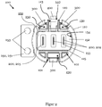
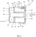
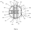
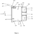
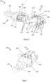
- the Figures 1 to 5 show different views of an embodiment of a device socket 100 according to a first aspect of the invention.
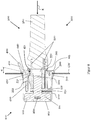
- the Figures 6 to 8 demonstrate a device plug 500 and a device plug system 600 according to the invention.
- the Figures 9A to 9C show a representation of possible (from the prior art) known hole cutouts 700 in a device housing wall GW, which can be used particularly preferably with the device socket 100.
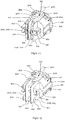
- the Figures 10 to 15 show different views of different exemplary embodiments of a device socket 100 according to a second aspect of the invention.
- FIGS. 1 to 5 show different views of an exemplary embodiment of a device socket 100 for releasable fastening in the hole cutout 700 of an electrical device according to the first aspect of the invention.
- the illustrated device socket 100 according to the second aspect can have all the features and developments of the device socket 100 according to the first aspect of the invention.
- the device socket 100 according to the first aspect can also have all the features and developments of the device socket 100 according to the second aspect of the invention. Therefore, a separate representation and description of the common features of the device sockets 100 according to the invention is dispensed with below. Rather, special features, deviations and differences between the respective device sockets 100 according to the invention are explicitly pointed out at the relevant points in the description.
- the device socket 100 has a socket body 110 with an outer wall 120.
- the outer wall 120 extends at least partially along and otherwise within a (virtual) cylindrical shape F. This is particularly evident from FIGS Figures 1 , 6 and 7 and 13 to 15.
- the cylindrical shape F is shown as an example.
- the cylindrical shape has an axis of rotational symmetry (not shown), which preferably extends along the longitudinal axis of the cylindrical shape F.
- the can body 110 can have a circular contour with a circular diameter in the range from 10 mm to 100 mm in a region in which the outer wall 120 extends along the cylindrical shape F.
- the can body 110 or the cylindrical shape can preferably have a diameter in a range from 18 mm to 38 mm, 23 mm to 33 mm and further preferably from 27 mm to 29 mm.
- the can body 110 or its outer wall 120 can have two straight first sections 101, which are opposite and parallel with respect to the rotational symmetry axis, within the cylindrical shape F, as for example in FIGS Figures 1 , 2nd , 4th and 6 shown.
- the feature is that the socket body 110 or the outer wall 120 has two, with respect to a rotational symmetry axis of the cylindrical shape F and preferably parallel, straight first sections 101 within the cylindrical shape F, which by at least two with respect to the axis of symmetry opposite and essentially extending along the cylindrical shape F, second sections 102 are connected, can always be found in the device socket 100 according to the second aspect.
- This is exemplary in the Figures 10 to 15 to recognize.
- the first straight sections 101 can preferably be connected by two second sections 102 lying opposite one another with respect to the axis of rotational symmetry and extending essentially along the cylindrical shape F.
- the first sections 101 and the second sections 102 can be arranged uniformly distributed over the circumference of the can body 110 or the cylindrical shape F.
- At least one of the second sections 102 can preferably extend in the direction of the rotational symmetry axis over an angular range of at least 20 ° or at least 30 ° or at least 40 ° or at least 60 ° or at least 90 ° or at least 120 ° or at least 130 °.
- the first sections 101 and the second sections 102 are particularly good Figures 1 , 2nd , 4th and 6 and 10 to 15 can be seen.
- the can body 110 can preferably extend longitudinally along the axis of rotational symmetry, as exemplified in FIGS Figures 1 to 8 and 13 to 15.
- the can body 110 can preferably have a longitudinal extent in a range from 10 mm to 100 mm.
- the can body 110 can preferably be made of plastic. Furthermore, it is also conceivable that the can body 110 is composed of several plastic components and has, for example, an elastic area for sealing. This can be achieved, for example, by means of a multi-component injection molding process.
- the socket body 110 also has a connector receiving space 150, which is surrounded by the outer wall 120 and has an insertion opening 151 for inserting, for example, a connector 500 described later in an insertion direction E.
- the connector receiving space 150 can extend from the insertion opening 151.
- this is the Figures 1 , 2nd and 8th and 10 to 12 can be seen.
- the insertion direction E results directly from the direction of insertion into the device socket 100 provided for a plug 500 of the device socket 100 Representations of the Figures 1 to 8 and 10 to 15, for example, a plug 500 of the device socket 100 is inserted and removed along the axis of rotation of the socket body 110.
- the connector receptacle 150 can have a substantially elongated, rectangular, asymmetrical and / or non-rotationally symmetrical cross-section when viewed in the insertion direction E. Like the one in particular Figures 1 and 2nd 10 and 12 can be seen, the long sides of the connector receptacle 150 can face the first sections 101. The narrow sides of the connector receptacle 150, however, can face the second sections 102.
- the plug receiving space 150 can also have at least one convex edge section 154.
- the connector receptacle 150 may further have at least one coding structure 155.
- the coding structure 155 can be formed, for example, as a projection from the convex edge section 154.
- the coding structure 155 can furthermore be designed to correspond with a coding structure partner of a plug 500 inserted into the plug receptacle 150 in order to enable the device socket 100 to be connected only with suitable plugs 500.
- the coding structure 155 can extend longitudinally in the insertion direction E (or in the direction of the axis of rotational symmetry). Furthermore, it is also conceivable that the coding structure 155 extends only partially in the insertion direction E.
- Figure 11 shows an embodiment in which only one coding structure 155 is provided.
- Figure 12 shows a further embodiment in which two coding structures 155 are provided.
- the coding structure 155 is shown as an example for the device socket 100 according to the second aspect. However, the coding structure 155 can also be provided in a corresponding manner for the device socket according to the second aspect of the invention.
- the device socket 100 also has at least two electrical contacts 200, 202, 205.
- the electrical contacts 200, 202, 205 are arranged within the cylindrical shape F and extend in such a way that they can be electrically contacted with the plug 500 inserted via the insertion opening 151. This can be the case, for example Figures 1 , 2nd and 8th and 10 to 15 are removed
- one of the contacts 200, 202, 205 of the device socket 100 according to the first aspect is a ground contact 205 Figures 1 , 2nd and 8th be removed.
- the device socket 100 according to the second aspect of the invention may also not have a ground contact 205, as for example in FIG Figure 14 shown.
- the Device socket according to the second aspect of the invention also have a ground contact 205, such as in the Figures 10 to 13 and 15 is shown.
- ground contact 205 There is preferably (essentially) no difference in their respective electrical conductivity or shape between the ground contact 205 and the at least one electrical contact 202 that is not a ground contact 205.
- the electrical contacts 200, 202, 205 can extend in a plane which preferably extends in or parallel to the axis of rotational symmetry and / or insertion direction E.
- the electrical contacts 200, 202, 205 can, seen in the insertion direction E, extend from a bottom section 152 of the socket body 110, which preferably delimits the connector receiving space 150 on a side opposite the insertion opening 151, into the connector receiving space 150 against the insertion direction E.
- the electrical contacts 200, 202, 205 can protrude from the bottom section 152 in the direction of the insertion opening 151. This is particularly the case Figures 1 , 2nd and 8th can be seen, but also in the Figures 10 to 12 indicated.
- the electrical contacts 200, 202, 205 can also be received or held in through openings 153, which connect the connector receiving space 150 to a rear side 160 of the socket body 110 via the base section 152.
- the electrical contacts 200, 202, 205 can preferably extend through the socket body 110 through the through openings 153 of the base section 152. This is exemplary in Figure 8 shown, but this is also from the Figures 13 to 15 forth.
- the electrical contacts 200, 202, 205 can be arranged next to one another, in particular with respect to an elongated direction of the plug receiving space 150, as in FIGS Figures 1 to 8 and 13 to 15 is shown as an example.
- the electrical contacts 200, 202, 205 can each have a plug contact section 220 for making electrical contact with the plug 500 inserted via the insertion opening 151. Furthermore, the electrical contacts 200, 202, 205 can have at least one device connection section 210 for connecting device-side electrical contacts 200, 202, 205.
- This exemplary embodiment is in particular in Figure 8 and partially in Figure 1 to recognize as well as in the Figures 10 to 12 indicated.
- the plug contact section 220 can, as in FIGS Figures 1 and 8th 10 and 12 are shown by way of example, facing the plug receiving space 150 and projecting into it.
- the device connection section 210 can be provided exposed on the rear side 160 or can be accessible from the rear side 160.
- the device connection section 210 can be designed, for example, as a plug-in tab or as a solder pin.
- further configurations of the device connection section 210 are also conceivable. This is exemplary in the Figures 1 , 3 to 8 such as 13 to 15 shown.
- the plug contact section 220 and the at least one device connection section 210 can be provided at opposite ends of the electrical contact 200, 202, 205, respectively.
- the electrical contacts 200, 202, 205 can thus have, for example, an elongated I shape, Y shape, an angled L shape or a T shape or any other desired shape.
- An exemplary embodiment is shown in which the electrical contacts 200, 202, 205 have a Y shape.
- the exemplary embodiment shown therein is not limited to the device socket 100 according to the second aspect, but can also be found for the device socket 100 according to the first aspect.
- the device connection sections 210 can extend away from one another in the T-shape.
- the respective device connection sections 210 can furthermore have through openings 211 in order to facilitate fastening with the cables on the device side. This is exemplary in the Figures 1 , 5 , 7 and 8th as well as 13 to 15.
- Separating sections 162 for spatial and preferably electrical separation of the individual electrical contacts 200, 202, 205 or device connection sections 210 can be provided on the rear side 160. As shown, these can be designed as partitions 162. They can preferably extend along the rear 160 along the rear from the bottom section 152. These separating sections 162 are also provided here within the cylindrical shape F. The separating sections 162 are particularly preferably formed integrally with the can body 110 or part of the same, or preferably at least made of the same material. Depending on the extent of the device connection sections 210 to the rear, the length of the separating sections 162 can be designed to match this. For example, the aforementioned Y-shape of the electrical contacts 200, 202, 205 requires a longer extension to the rear (cf. Figure 15 ) than the T-shape requires (cf. e.g. Figures 3 , 6 , 13 and 14 ), so that the latter configuration enables an overall more compact design of the device socket 100.
- the electrical contacts 200, 202, 205 can be detachably connected to the socket body 110.
- the electrical contacts 200, 202, 205 can have, for example, fastening cutouts 260, into which fastening springs 161 on the rear 160 engage.
- the fastening springs 161 are preferably part of and more preferably integrally formed with the separating sections 162. This is exemplary in the Figures 4 , 5 , 6 and 8th and 13 to 15.
- the electrical contacts 200, 202, 205 can have a stop section 231 with which the respective electrical contact 200, 202, 205 bears against the base section 152. This is for example in Figure 8 shown.
- the device socket 100 can furthermore have a support section 116 for resting on an edge region of the hole section 700 receiving the box body 110, at least the rear side of the box body 110 being received by the hole section 700.
- the support section 116 can be formed, for example, by an annular projection 115 of the can body 110 (extending outwards) that runs around the outside of the outer wall 120 on the outside, as exemplarily in FIGS Figures 1 to 8 and 10 to 15 is shown.
- the support section 116 can also be provided on a front end of the can body 110 as seen in the insertion direction E. Alternatively or additionally, the support section 116 can extend in a plane spanning the insertion opening 151.
- the device socket 100 can also have at least one latching element 300. This is exemplary in the Figures 1 to 8 and 10 to 15 are shown.
- the locking element 300 can be provided in a region of the outer wall 120 and / or can extend along the cylindrical shape F.
- the locking element 300 can preferably be provided to be movable, in particular pivotable.
- the latching element 300 can have latching projections 310 projecting laterally away from the axis of rotational symmetry and beyond the cylindrical shape, in order to detachably hold the device socket 100 in a part of the hole cutout 700 following the cross-sectional contour of the outer wall 120.
- the outer wall 120 in the region of the latching element 300 can have a pivoting space section which, with respect to the cylindrical shape F, forms a free space 130, which preferably extends parallel to the axis of rotational symmetry, in order to thus move the respective latching element 300, in particular pivoting it allow to allow the assembled can body 110 to be released from the hole cutout 700.
- the device socket 100 can do several Have latching elements 300 which, such as in the Figures 4 and 10 to 12, can be arranged evenly distributed over the circumference of the can body 110.
- the device socket 100 can furthermore have a connector holding lever 400 which has a latching projection 430 which projects into the connector receiving space 150 between a latching position, in which it preferably radially with respect to the axis of rotational symmetry or with respect to the direction of insertion E as seen in the direction of insertion E, and a release position, in which it does not protrude into the plug receiving space 150, as seen in the insertion direction E, is provided movably.
- the Figures 1 to 8 and 10 to 15 show the connector holding lever 400 in the latching position.
- the latching projection 430 can have a run-up slope 431 which runs obliquely with respect to the insertion direction E, in order to move the connector holding lever 400 from the latching position into the release position only when the connector 500 is inserted into the connector receiving space 150.
- the chamfer 431 is particularly in the Figures 1 and 8th recognizable and is also in Figure 10 drawn.
- the plug holding lever 400 can furthermore have a spring section 420 with a fastening end, with which the plug holding lever 400 is fastened to the socket body 110 or the outer wall 120.
- the spring section 420 can furthermore have a latching end which is spaced from or opposite to the fastening end and which has the latching projection 430 in order to pivot the connector holding lever 400 over the fastening end.
- the plug holding lever 400 (and in particular the spring section 420) can extend from the fastening end to the latching end essentially along the axis of rotational symmetry and towards the insertion opening 151. This can be particularly the case Figure 8 as well as the Figures 13 to 15 be removed.
- the connector holding lever 400 may be provided on a connector detent portion of the outer wall 120.
- the connector holding lever 400 can be provided on one of the first sections 101, which can be designed as a recess 113 with respect to the cylindrical shape F toward the axis of rotational symmetry.
- the recess 113 can be designed such that the connector holding lever 400 is arranged within the recess 113 in any pivot position, in particular in the latching position and the release position. It is also possible here that a further free space 140 is formed by the recess 113, as for example in FIG Figure 2 and 13 to 15 is shown.
- the connector holding lever 400 may further include a grip portion 410 which may extend from the latching end and counter to the insertion direction E and may protrude from the socket body 110 to enable an operator to move the connector holding lever 400 between the latching position and the release position .
- the grip portion 410 is in particular the Figures 3 and 5 and 13 to 15 shown in an advantageous manner.
- the grip section 410 can have a stop section 440 which, with respect to a contact plane perpendicular to the axis of rotational symmetry, is inclined by an angle ⁇ against the insertion direction E in the latching position in such a way that the stop section 440 extends in the release position in the contact plane.
- the contact plane can correspond to a plane spanned by the insertion opening 151.
- the angle ⁇ can extend over an angular range of at least 5 °, 10 °, 20 ° or 50 °.
- the device socket 100 according to the first aspect of the invention in contrast to the device socket 100 according to the second aspect of the invention, additionally has a ground connection 251, which is electrically coupled to the ground contact 205 and laterally in a direction from the outer wall 120 and essentially orthogonally extends from an axis of rotational symmetry of the cylindrical shape F to the outside.
- the device socket 100 according to the second aspect can be primarily intended for applications in which such a grounding of the device housing wall GW and / or the device is not required.
- the device socket 100 can also be used for those applications that require the device housing wall GW to be grounded.
- the ground connection 251 can extend away from one of the second sections 102.
- the ground connection 251 can extend flatly in a plane orthogonal to the axis of rotational symmetry. This is exemplified in the Figures 1 , 2nd , 4th shown.
- the ground terminal 251 may be connected to the ground contact 205 via a connection section 252 to form a ground contact element 250.
- the connecting section 252 can directly connect to the ground contact 205, such as in particular Figures 3 and 4th can be seen.
- the ground connection 251 and the ground contact 205 can be formed integrally with one another via the connecting section 252, such as that Figures 3 and 4th can be seen.
- Both the contacts 200, 202, 205 and the grounding contact element 250 can preferably be formed as a stamped and bent part.
- the electrical contacts 200, 202, 205 can be made, for example, of copper or another (noble) metal.
- the ground connection 251 and / or the connecting section 252 can also be produced from a metallic material.
- the ground connection 251 can also be detachably connected to the socket body 110.
- the Figures 13 and 15 can also be understood as a representation of a device socket 100 according to the first aspect, in which the ground connection 251 has been detached from the socket body 110 or can be used.
- the ground connection 251 can also have two ground connection openings 253, the geometric center of which can be at a distance from the axis of rotational symmetry in the range from 10 mm to 50 mm.
- the two ground connection openings 253 can be arranged mirror-symmetrically with respect to the ground connection 251 and / or with respect to a radial of the rotational symmetry axis. This is shown in particular by Figures 1 to 4 .
- the connecting section 252 can extend laterally along the outer wall 120 and substantially parallel to the axis of rotational symmetry.
- the connecting section 252 can extend along the second section 102 having the ground connection 251. This is for example in Figure 3 shown.
- the ground connection 251 can also be provided on a section of the outer wall 120 which is designed as the recess 112 with respect to the cylindrical shape F toward the axis of rotational symmetry.
- the connecting section 252 can preferably extend along the recess 112 and further preferably within the cylindrical shape F. This is for example in Figure 3 shown.
- the Figures 13 to 15 also show the return 112 as an example.
- the ground connection 251 can also be opposite the at least one convex edge section 154 with respect to the connector receptacle space 150.
- the ground connection 251 can also extend in a plane in which the support section 116 also extends and which can preferably be orthogonal to the insertion direction E or orthogonal to the axis of rotational symmetry. In particular, this can Figure 1 be removed.
- the Figures 6 to 8 also show a device plug system 600.
- the device plug system 600 has the device socket 100. Both the device socket 100 according to the first aspect and / or according to the second aspect of the invention can be used in the device plug system 600.
- the device plug system 600 also has a device plug 500 which corresponds to the device socket 100.
- the device plug 500 is set up to make electrical contact with the contacts 200, 202, 205 of the device socket 100 by receiving the device plug 500 in the plug receiving space 150.
- the device plug 500 can have a contour corresponding to the plug receiving space 150 of the device socket 100 for receiving the device plug 500 in the plug receiving space 150.
- the device plug 500 can have a cable 560, which is connected to the plug head 530 of the device plug 500.
- a plug contact section 515 can be provided on the plug head 530, by means of which the plug head 530 bears against the device socket 100.
- the plug head 530 can also have an insertion section 550 in which the electrical contacts 520 of the device plug 500 can be provided. This is particularly true in Figure 8 shown.
- the device plug 500 can have a latching structure 531 which corresponds to the latching projection 430 of the connector holding lever 400 in order to detachably hold the device connector 500 in the connector receiving space 150 in the latching position of the connector holding lever 400.
- the device plug 500 can furthermore have a coding structure partner 555 corresponding to the coding structure 155 in order to prevent the insertion of unsuitable device plugs 500 into the device socket 100 (see Figure 6 ).
- FIGS. 9A to 9C show different hole cutouts 700 from a device housing wall GW, which can be used particularly preferably with the presented device sockets 100 according to the first and the second aspect of the invention and with the presented device plug system 600.
- the device sockets 100 are particularly preferably designed such that their contour corresponds to the contour of the hole cutout 700 or at least partially follows the contour of the hole cutout 700. All of the following dimensions also include the deviations due to manufacturing tolerances.
- the hole cutouts 700 each have a circular contour with two parallel straight sections lying opposite one another with respect to the center of the circle.
- the circular contour of the respective hole cutout 700 can extend with a circular diameter of at least 10 mm, 15 mm, 20 mm or 25 mm.
- the respective circular contours can have a circle diameter of Extend a maximum of 100mm, 90mm, 80mm, 70mm, 60mm, 50mm, 40mm or 30mm.
- the circular contour particularly preferably has a circular diameter of 28.5 mm.
- the straight sections 701 can be spaced apart from one another in a range of at least 10 mm, 15 mm, 20 mm or 25 mm (horizontally).
- the straight sections 701 are particularly preferably 26.0 mm apart.
- the hole cutout 700 can also have further punched-out areas 705, which can be provided, for example, for fastening the ground connection 251 and / or for additionally securing or fastening the device socket 100.
- the further punched-out portions 705 can be formed by two circular sections spaced apart from one another.
- the two circular sections preferably have a distance in a range of at least 10 mm, 15 mm, 20 mm or 25 mm.
- the two circular sections are particularly preferably spaced 14.0 mm apart.
- the two circular sections can also each have a vertical spacing from the center of the circular contour.
- the vertical spacing can have a range of at least 10 mm, 15 mm, 20 mm or 25 mm.
- the two circular sections are particularly preferably vertically spaced 18.0 mm from the center of the circular contour.
Landscapes
- Details Of Connecting Devices For Male And Female Coupling (AREA)
- Connector Housings Or Holding Contact Members (AREA)
Priority Applications (1)
| Application Number | Priority Date | Filing Date | Title |
|---|---|---|---|
| SI201930220T SI3633802T1 (sl) | 2018-10-01 | 2019-09-26 | Vtičnica naprave, vtič naprave in sistem vtiča naprave |
Applications Claiming Priority (1)
| Application Number | Priority Date | Filing Date | Title |
|---|---|---|---|
| DE202018105641.7U DE202018105641U1 (de) | 2018-10-01 | 2018-10-01 | Gerätesteckdose, Gerätestecker und Gerätesteckersystem |
Publications (2)
| Publication Number | Publication Date |
|---|---|
| EP3633802A1 true EP3633802A1 (fr) | 2020-04-08 |
| EP3633802B1 EP3633802B1 (fr) | 2022-03-02 |
Family
ID=68069634
Family Applications (1)
| Application Number | Title | Priority Date | Filing Date |
|---|---|---|---|
| EP19199726.1A Active EP3633802B1 (fr) | 2018-10-01 | 2019-09-26 | Prise de courant d'appareil, connecteur d'appareil et système de connecteur d'appareil |
Country Status (5)
| Country | Link |
|---|---|
| EP (1) | EP3633802B1 (fr) |
| CN (1) | CN110970777A (fr) |
| DE (1) | DE202018105641U1 (fr) |
| PL (1) | PL3633802T3 (fr) |
| SI (1) | SI3633802T1 (fr) |
Families Citing this family (3)
| Publication number | Priority date | Publication date | Assignee | Title |
|---|---|---|---|---|
| JP7453067B2 (ja) | 2020-06-05 | 2024-03-19 | 矢崎総業株式会社 | コネクタセット |
| CN113328316B (zh) * | 2021-04-25 | 2022-06-03 | 佛山照明智达电工科技有限公司 | 一种插座点焊一体机 |
| DE102021127030B3 (de) * | 2021-10-19 | 2022-12-22 | Md Elektronik Gmbh | Steckverbinder |
Citations (7)
| Publication number | Priority date | Publication date | Assignee | Title |
|---|---|---|---|---|
| US3723942A (en) * | 1972-03-03 | 1973-03-27 | Arrow Hart Inc | Grounding clip electric receptacles |
| DE2725796A1 (de) * | 1977-06-08 | 1978-12-21 | Maschf Augsburg Nuernberg Ag | Hochvakuumdichte steckdose |
| EP0597473A2 (fr) * | 1992-11-13 | 1994-05-18 | Alcatel Components Limited | Assemblage de connecteur électrique |
| US20040077214A1 (en) * | 2001-12-17 | 2004-04-22 | James Turek | Electrical connection bulkhead header |
| US7182637B2 (en) * | 2002-05-30 | 2007-02-27 | Heyco, Inc. | Connectors for under cabinet lighting |
| EP2056412A2 (fr) * | 2007-10-29 | 2009-05-06 | DDK Ltd. | Connecteur électrique |
| WO2016033757A1 (fr) * | 2014-09-03 | 2016-03-10 | Micro Motion, Inc. | Connecteur à verrouillage |
Family Cites Families (5)
| Publication number | Priority date | Publication date | Assignee | Title |
|---|---|---|---|---|
| US5807125A (en) * | 1997-02-19 | 1998-09-15 | Molex Incorporated | System for mounting an electrical connector in a support structure |
| US7326063B1 (en) * | 2007-02-06 | 2008-02-05 | Tyco Electronics Corporation | Panel mount connector housing |
| DE202010000547U1 (de) * | 2010-04-09 | 2010-06-10 | ABL SURSUM Bayerische Elektrozubehör GmbH & Co. KG | Elektrische Steckdose oder Kupplung mit Beleuchtungseinrichtung |
| CN107919579A (zh) * | 2016-10-10 | 2018-04-17 | 鸿富锦精密电子(天津)有限公司 | 插座及应用所述插座的连接组件 |
| DE102017122649A1 (de) * | 2017-09-28 | 2019-03-28 | Unger Kabel-Konfektionstechnik GmbH | Gerätestecker mit Sperrsystem für die Gerätedose bei Fehlmontage, Geräteanschlusssystem und Elektrogerät |
-
2018
- 2018-10-01 DE DE202018105641.7U patent/DE202018105641U1/de active Active
-
2019
- 2019-09-26 SI SI201930220T patent/SI3633802T1/sl unknown
- 2019-09-26 EP EP19199726.1A patent/EP3633802B1/fr active Active
- 2019-09-26 PL PL19199726.1T patent/PL3633802T3/pl unknown
- 2019-09-29 CN CN201910935027.2A patent/CN110970777A/zh active Pending
Patent Citations (7)
| Publication number | Priority date | Publication date | Assignee | Title |
|---|---|---|---|---|
| US3723942A (en) * | 1972-03-03 | 1973-03-27 | Arrow Hart Inc | Grounding clip electric receptacles |
| DE2725796A1 (de) * | 1977-06-08 | 1978-12-21 | Maschf Augsburg Nuernberg Ag | Hochvakuumdichte steckdose |
| EP0597473A2 (fr) * | 1992-11-13 | 1994-05-18 | Alcatel Components Limited | Assemblage de connecteur électrique |
| US20040077214A1 (en) * | 2001-12-17 | 2004-04-22 | James Turek | Electrical connection bulkhead header |
| US7182637B2 (en) * | 2002-05-30 | 2007-02-27 | Heyco, Inc. | Connectors for under cabinet lighting |
| EP2056412A2 (fr) * | 2007-10-29 | 2009-05-06 | DDK Ltd. | Connecteur électrique |
| WO2016033757A1 (fr) * | 2014-09-03 | 2016-03-10 | Micro Motion, Inc. | Connecteur à verrouillage |
Also Published As
| Publication number | Publication date |
|---|---|
| CN110970777A (zh) | 2020-04-07 |
| SI3633802T1 (sl) | 2022-06-30 |
| DE202018105641U1 (de) | 2020-01-03 |
| EP3633802B1 (fr) | 2022-03-02 |
| PL3633802T3 (pl) | 2022-07-18 |
Similar Documents
| Publication | Publication Date | Title |
|---|---|---|
| EP2016649B1 (fr) | Système de connexion enfichable | |
| EP3719933B1 (fr) | Dispositif de connexion enfichable pourvu d'au moins un connecteur enfichable | |
| DE10012387C2 (de) | Anordnung zum Verbinden eines Kabels mit einem Kraftfahrzeugbatteriepol | |
| EP0754357B1 (fr) | Systeme de connexion pour conducteurs electriques | |
| DE102019106980B3 (de) | Kontaktträger und Steckverbinder für eine geschirmte hybride Kontaktanordnung | |
| DE112016002791B4 (de) | Gemeinschaftsverbinder | |
| EP3164911A1 (fr) | Fiche de raccordement | |
| EP3633802B1 (fr) | Prise de courant d'appareil, connecteur d'appareil et système de connecteur d'appareil | |
| DE102015216545A1 (de) | Gehäuseanordnung, elektrischer Verbinder umfassend eine Gehäuseanordnung und elektrische Verbindungsanordnung umfassend einen elektrischen Verbinder | |
| EP3676918A1 (fr) | Connecteur enfichable coudé et procédé de fabrication | |
| DE102008054585B4 (de) | Winkelsteckverbindung für geschirmte Kabel | |
| EP4292173B1 (fr) | Insert pour connecteur | |
| DE102004004203B4 (de) | Verbindungsanordnung mit einem Verbindungselement und einem Lampensockel | |
| DE69902947T2 (de) | Koaxiale kabelverbindungseinrichtung | |
| WO2024017778A1 (fr) | Connecteur enfichable configurable sans outil à direction de sortie de câble variable | |
| EP1206008B1 (fr) | Connecteur pour connecter des lignes électriques à un appareil électrique, en particulier pour un moteur | |
| DE202005007221U1 (de) | Befestigungseinsatz für einen Steckverbinder | |
| EP1720222B1 (fr) | Connecteur électrique, notamment pour des systèmes d' allumage d' airbag | |
| EP3577725B1 (fr) | Connecteur enfichable équipé d'un pont de connexion de conducteurs de protection | |
| EP3895254A1 (fr) | Pièce de connecteur pour la mise en contact dans plusieurs directions spatiales | |
| WO2021122624A1 (fr) | Connexion de fiche, module de fiche et élément de contact | |
| BE1032009B1 (de) | Steckverbinderteil mit Zugentlastung | |
| EP4231463B1 (fr) | Connecteur à monter sur une carte de circuit imprimé | |
| DE10349777B4 (de) | Elektrischer Steckverbinder | |
| DE10334071B4 (de) | Steckverbindungssystem mit integrierter Verriegelung |
Legal Events
| Date | Code | Title | Description |
|---|---|---|---|
| PUAI | Public reference made under article 153(3) epc to a published international application that has entered the european phase |
Free format text: ORIGINAL CODE: 0009012 |
|
| STAA | Information on the status of an ep patent application or granted ep patent |
Free format text: STATUS: THE APPLICATION HAS BEEN PUBLISHED |
|
| AK | Designated contracting states |
Kind code of ref document: A1 Designated state(s): AL AT BE BG CH CY CZ DE DK EE ES FI FR GB GR HR HU IE IS IT LI LT LU LV MC MK MT NL NO PL PT RO RS SE SI SK SM TR |
|
| AX | Request for extension of the european patent |
Extension state: BA ME |
|
| STAA | Information on the status of an ep patent application or granted ep patent |
Free format text: STATUS: REQUEST FOR EXAMINATION WAS MADE |
|
| 17P | Request for examination filed |
Effective date: 20201006 |
|
| RBV | Designated contracting states (corrected) |
Designated state(s): AL AT BE BG CH CY CZ DE DK EE ES FI FR GB GR HR HU IE IS IT LI LT LU LV MC MK MT NL NO PL PT RO RS SE SI SK SM TR |
|
| GRAP | Despatch of communication of intention to grant a patent |
Free format text: ORIGINAL CODE: EPIDOSNIGR1 |
|
| STAA | Information on the status of an ep patent application or granted ep patent |
Free format text: STATUS: GRANT OF PATENT IS INTENDED |
|
| RIC1 | Information provided on ipc code assigned before grant |
Ipc: H01R 13/627 20060101ALN20210914BHEP Ipc: H01R 13/655 20060101ALI20210914BHEP Ipc: H01R 13/74 20060101ALI20210914BHEP Ipc: H01R 13/652 20060101AFI20210914BHEP |
|
| INTG | Intention to grant announced |
Effective date: 20211007 |
|
| GRAS | Grant fee paid |
Free format text: ORIGINAL CODE: EPIDOSNIGR3 |
|
| GRAA | (expected) grant |
Free format text: ORIGINAL CODE: 0009210 |
|
| STAA | Information on the status of an ep patent application or granted ep patent |
Free format text: STATUS: THE PATENT HAS BEEN GRANTED |
|
| AK | Designated contracting states |
Kind code of ref document: B1 Designated state(s): AL AT BE BG CH CY CZ DE DK EE ES FI FR GB GR HR HU IE IS IT LI LT LU LV MC MK MT NL NO PL PT RO RS SE SI SK SM TR |
|
| REG | Reference to a national code |
Ref country code: GB Ref legal event code: FG4D Free format text: NOT ENGLISH |
|
| REG | Reference to a national code |
Ref country code: CH Ref legal event code: EP Ref country code: AT Ref legal event code: REF Ref document number: 1473028 Country of ref document: AT Kind code of ref document: T Effective date: 20220315 |
|
| REG | Reference to a national code |
Ref country code: DE Ref legal event code: R096 Ref document number: 502019003546 Country of ref document: DE |
|
| REG | Reference to a national code |
Ref country code: IE Ref legal event code: FG4D Free format text: LANGUAGE OF EP DOCUMENT: GERMAN |
|
| REG | Reference to a national code |
Ref country code: LT Ref legal event code: MG9D |
|
| REG | Reference to a national code |
Ref country code: NL Ref legal event code: MP Effective date: 20220302 |
|
| PG25 | Lapsed in a contracting state [announced via postgrant information from national office to epo] |
Ref country code: SE Free format text: LAPSE BECAUSE OF FAILURE TO SUBMIT A TRANSLATION OF THE DESCRIPTION OR TO PAY THE FEE WITHIN THE PRESCRIBED TIME-LIMIT Effective date: 20220302 Ref country code: RS Free format text: LAPSE BECAUSE OF FAILURE TO SUBMIT A TRANSLATION OF THE DESCRIPTION OR TO PAY THE FEE WITHIN THE PRESCRIBED TIME-LIMIT Effective date: 20220302 Ref country code: NO Free format text: LAPSE BECAUSE OF FAILURE TO SUBMIT A TRANSLATION OF THE DESCRIPTION OR TO PAY THE FEE WITHIN THE PRESCRIBED TIME-LIMIT Effective date: 20220602 Ref country code: LT Free format text: LAPSE BECAUSE OF FAILURE TO SUBMIT A TRANSLATION OF THE DESCRIPTION OR TO PAY THE FEE WITHIN THE PRESCRIBED TIME-LIMIT Effective date: 20220302 Ref country code: HR Free format text: LAPSE BECAUSE OF FAILURE TO SUBMIT A TRANSLATION OF THE DESCRIPTION OR TO PAY THE FEE WITHIN THE PRESCRIBED TIME-LIMIT Effective date: 20220302 Ref country code: ES Free format text: LAPSE BECAUSE OF FAILURE TO SUBMIT A TRANSLATION OF THE DESCRIPTION OR TO PAY THE FEE WITHIN THE PRESCRIBED TIME-LIMIT Effective date: 20220302 Ref country code: BG Free format text: LAPSE BECAUSE OF FAILURE TO SUBMIT A TRANSLATION OF THE DESCRIPTION OR TO PAY THE FEE WITHIN THE PRESCRIBED TIME-LIMIT Effective date: 20220602 |
|
| PG25 | Lapsed in a contracting state [announced via postgrant information from national office to epo] |
Ref country code: LV Free format text: LAPSE BECAUSE OF FAILURE TO SUBMIT A TRANSLATION OF THE DESCRIPTION OR TO PAY THE FEE WITHIN THE PRESCRIBED TIME-LIMIT Effective date: 20220302 Ref country code: GR Free format text: LAPSE BECAUSE OF FAILURE TO SUBMIT A TRANSLATION OF THE DESCRIPTION OR TO PAY THE FEE WITHIN THE PRESCRIBED TIME-LIMIT Effective date: 20220603 Ref country code: FI Free format text: LAPSE BECAUSE OF FAILURE TO SUBMIT A TRANSLATION OF THE DESCRIPTION OR TO PAY THE FEE WITHIN THE PRESCRIBED TIME-LIMIT Effective date: 20220302 |
|
| PG25 | Lapsed in a contracting state [announced via postgrant information from national office to epo] |
Ref country code: NL Free format text: LAPSE BECAUSE OF FAILURE TO SUBMIT A TRANSLATION OF THE DESCRIPTION OR TO PAY THE FEE WITHIN THE PRESCRIBED TIME-LIMIT Effective date: 20220302 |
|
| PG25 | Lapsed in a contracting state [announced via postgrant information from national office to epo] |
Ref country code: SM Free format text: LAPSE BECAUSE OF FAILURE TO SUBMIT A TRANSLATION OF THE DESCRIPTION OR TO PAY THE FEE WITHIN THE PRESCRIBED TIME-LIMIT Effective date: 20220302 Ref country code: SK Free format text: LAPSE BECAUSE OF FAILURE TO SUBMIT A TRANSLATION OF THE DESCRIPTION OR TO PAY THE FEE WITHIN THE PRESCRIBED TIME-LIMIT Effective date: 20220302 Ref country code: RO Free format text: LAPSE BECAUSE OF FAILURE TO SUBMIT A TRANSLATION OF THE DESCRIPTION OR TO PAY THE FEE WITHIN THE PRESCRIBED TIME-LIMIT Effective date: 20220302 Ref country code: PT Free format text: LAPSE BECAUSE OF FAILURE TO SUBMIT A TRANSLATION OF THE DESCRIPTION OR TO PAY THE FEE WITHIN THE PRESCRIBED TIME-LIMIT Effective date: 20220704 Ref country code: EE Free format text: LAPSE BECAUSE OF FAILURE TO SUBMIT A TRANSLATION OF THE DESCRIPTION OR TO PAY THE FEE WITHIN THE PRESCRIBED TIME-LIMIT Effective date: 20220302 Ref country code: CZ Free format text: LAPSE BECAUSE OF FAILURE TO SUBMIT A TRANSLATION OF THE DESCRIPTION OR TO PAY THE FEE WITHIN THE PRESCRIBED TIME-LIMIT Effective date: 20220302 |
|
| PG25 | Lapsed in a contracting state [announced via postgrant information from national office to epo] |
Ref country code: IS Free format text: LAPSE BECAUSE OF FAILURE TO SUBMIT A TRANSLATION OF THE DESCRIPTION OR TO PAY THE FEE WITHIN THE PRESCRIBED TIME-LIMIT Effective date: 20220702 Ref country code: AL Free format text: LAPSE BECAUSE OF FAILURE TO SUBMIT A TRANSLATION OF THE DESCRIPTION OR TO PAY THE FEE WITHIN THE PRESCRIBED TIME-LIMIT Effective date: 20220302 |
|
| REG | Reference to a national code |
Ref country code: DE Ref legal event code: R097 Ref document number: 502019003546 Country of ref document: DE |
|
| PLBE | No opposition filed within time limit |
Free format text: ORIGINAL CODE: 0009261 |
|
| STAA | Information on the status of an ep patent application or granted ep patent |
Free format text: STATUS: NO OPPOSITION FILED WITHIN TIME LIMIT |
|
| PG25 | Lapsed in a contracting state [announced via postgrant information from national office to epo] |
Ref country code: DK Free format text: LAPSE BECAUSE OF FAILURE TO SUBMIT A TRANSLATION OF THE DESCRIPTION OR TO PAY THE FEE WITHIN THE PRESCRIBED TIME-LIMIT Effective date: 20220302 |
|
| 26N | No opposition filed |
Effective date: 20221205 |
|
| PG25 | Lapsed in a contracting state [announced via postgrant information from national office to epo] |
Ref country code: MC Free format text: LAPSE BECAUSE OF FAILURE TO SUBMIT A TRANSLATION OF THE DESCRIPTION OR TO PAY THE FEE WITHIN THE PRESCRIBED TIME-LIMIT Effective date: 20220302 |
|
| REG | Reference to a national code |
Ref country code: CH Ref legal event code: PL |
|
| REG | Reference to a national code |
Ref country code: BE Ref legal event code: MM Effective date: 20220930 |
|
| PG25 | Lapsed in a contracting state [announced via postgrant information from national office to epo] |
Ref country code: LU Free format text: LAPSE BECAUSE OF NON-PAYMENT OF DUE FEES Effective date: 20220926 |
|
| PG25 | Lapsed in a contracting state [announced via postgrant information from national office to epo] |
Ref country code: LI Free format text: LAPSE BECAUSE OF NON-PAYMENT OF DUE FEES Effective date: 20220930 Ref country code: IE Free format text: LAPSE BECAUSE OF NON-PAYMENT OF DUE FEES Effective date: 20220926 Ref country code: CH Free format text: LAPSE BECAUSE OF NON-PAYMENT OF DUE FEES Effective date: 20220930 |
|
| PG25 | Lapsed in a contracting state [announced via postgrant information from national office to epo] |
Ref country code: BE Free format text: LAPSE BECAUSE OF NON-PAYMENT OF DUE FEES Effective date: 20220930 |
|
| PG25 | Lapsed in a contracting state [announced via postgrant information from national office to epo] |
Ref country code: HU Free format text: LAPSE BECAUSE OF FAILURE TO SUBMIT A TRANSLATION OF THE DESCRIPTION OR TO PAY THE FEE WITHIN THE PRESCRIBED TIME-LIMIT; INVALID AB INITIO Effective date: 20190926 |
|
| PG25 | Lapsed in a contracting state [announced via postgrant information from national office to epo] |
Ref country code: CY Free format text: LAPSE BECAUSE OF FAILURE TO SUBMIT A TRANSLATION OF THE DESCRIPTION OR TO PAY THE FEE WITHIN THE PRESCRIBED TIME-LIMIT Effective date: 20220302 |
|
| PG25 | Lapsed in a contracting state [announced via postgrant information from national office to epo] |
Ref country code: MK Free format text: LAPSE BECAUSE OF FAILURE TO SUBMIT A TRANSLATION OF THE DESCRIPTION OR TO PAY THE FEE WITHIN THE PRESCRIBED TIME-LIMIT Effective date: 20220302 |
|
| PG25 | Lapsed in a contracting state [announced via postgrant information from national office to epo] |
Ref country code: MT Free format text: LAPSE BECAUSE OF FAILURE TO SUBMIT A TRANSLATION OF THE DESCRIPTION OR TO PAY THE FEE WITHIN THE PRESCRIBED TIME-LIMIT Effective date: 20220302 |
|
| PGFP | Annual fee paid to national office [announced via postgrant information from national office to epo] |
Ref country code: DE Payment date: 20250922 Year of fee payment: 7 |
|
| PGFP | Annual fee paid to national office [announced via postgrant information from national office to epo] |
Ref country code: TR Payment date: 20250918 Year of fee payment: 7 Ref country code: PL Payment date: 20250918 Year of fee payment: 7 |
|
| PGFP | Annual fee paid to national office [announced via postgrant information from national office to epo] |
Ref country code: GB Payment date: 20250923 Year of fee payment: 7 |
|
| PGFP | Annual fee paid to national office [announced via postgrant information from national office to epo] |
Ref country code: FR Payment date: 20250925 Year of fee payment: 7 |
|
| PGFP | Annual fee paid to national office [announced via postgrant information from national office to epo] |
Ref country code: SI Payment date: 20250915 Year of fee payment: 7 |
|
| REG | Reference to a national code |
Ref country code: AT Ref legal event code: MM01 Ref document number: 1473028 Country of ref document: AT Kind code of ref document: T Effective date: 20240926 |
|
| PG25 | Lapsed in a contracting state [announced via postgrant information from national office to epo] |
Ref country code: AT Free format text: LAPSE BECAUSE OF NON-PAYMENT OF DUE FEES Effective date: 20240926 |
|
| PGFP | Annual fee paid to national office [announced via postgrant information from national office to epo] |
Ref country code: IT Payment date: 20250930 Year of fee payment: 7 |
|
| PGFP | Annual fee paid to national office [announced via postgrant information from national office to epo] |
Ref country code: AT Payment date: 20260410 Year of fee payment: 5 |