EP2340432B1 - Procédé d'analyse d'un analyte dans un échantillon d'eau à l'aide d'un dispositif d'analyse d'eau mobile - Google Patents
Procédé d'analyse d'un analyte dans un échantillon d'eau à l'aide d'un dispositif d'analyse d'eau mobile Download PDFInfo
- Publication number
- EP2340432B1 EP2340432B1 EP09783492.3A EP09783492A EP2340432B1 EP 2340432 B1 EP2340432 B1 EP 2340432B1 EP 09783492 A EP09783492 A EP 09783492A EP 2340432 B1 EP2340432 B1 EP 2340432B1
- Authority
- EP
- European Patent Office
- Prior art keywords
- reagent
- water sample
- section
- sample
- measuring
- Prior art date
- Legal status (The legal status is an assumption and is not a legal conclusion. Google has not performed a legal analysis and makes no representation as to the accuracy of the status listed.)
- Active
Links
Images


Classifications
-
- G—PHYSICS
- G01—MEASURING; TESTING
- G01N—INVESTIGATING OR ANALYSING MATERIALS BY DETERMINING THEIR CHEMICAL OR PHYSICAL PROPERTIES
- G01N33/00—Investigating or analysing materials by specific methods not covered by groups G01N1/00 - G01N31/00
- G01N33/18—Water
- G01N33/1893—Water using flow cells
-
- B—PERFORMING OPERATIONS; TRANSPORTING
- B01—PHYSICAL OR CHEMICAL PROCESSES OR APPARATUS IN GENERAL
- B01L—CHEMICAL OR PHYSICAL LABORATORY APPARATUS FOR GENERAL USE
- B01L3/00—Containers or dishes for laboratory use, e.g. laboratory glassware; Droppers
- B01L3/50—Containers for the purpose of retaining a material to be analysed, e.g. test tubes
- B01L3/502—Containers for the purpose of retaining a material to be analysed, e.g. test tubes with fluid transport, e.g. in multi-compartment structures
- B01L3/5027—Containers for the purpose of retaining a material to be analysed, e.g. test tubes with fluid transport, e.g. in multi-compartment structures by integrated microfluidic structures, i.e. dimensions of channels and chambers are such that surface tension forces are important, e.g. lab-on-a-chip
- B01L3/502715—Containers for the purpose of retaining a material to be analysed, e.g. test tubes with fluid transport, e.g. in multi-compartment structures by integrated microfluidic structures, i.e. dimensions of channels and chambers are such that surface tension forces are important, e.g. lab-on-a-chip characterised by interfacing components, e.g. fluidic, electrical, optical or mechanical interfaces
-
- B—PERFORMING OPERATIONS; TRANSPORTING
- B01—PHYSICAL OR CHEMICAL PROCESSES OR APPARATUS IN GENERAL
- B01L—CHEMICAL OR PHYSICAL LABORATORY APPARATUS FOR GENERAL USE
- B01L3/00—Containers or dishes for laboratory use, e.g. laboratory glassware; Droppers
- B01L3/50—Containers for the purpose of retaining a material to be analysed, e.g. test tubes
- B01L3/502—Containers for the purpose of retaining a material to be analysed, e.g. test tubes with fluid transport, e.g. in multi-compartment structures
- B01L3/5027—Containers for the purpose of retaining a material to be analysed, e.g. test tubes with fluid transport, e.g. in multi-compartment structures by integrated microfluidic structures, i.e. dimensions of channels and chambers are such that surface tension forces are important, e.g. lab-on-a-chip
- B01L3/50273—Containers for the purpose of retaining a material to be analysed, e.g. test tubes with fluid transport, e.g. in multi-compartment structures by integrated microfluidic structures, i.e. dimensions of channels and chambers are such that surface tension forces are important, e.g. lab-on-a-chip characterised by the means or forces applied to move the fluids
-
- G—PHYSICS
- G01—MEASURING; TESTING
- G01N—INVESTIGATING OR ANALYSING MATERIALS BY DETERMINING THEIR CHEMICAL OR PHYSICAL PROPERTIES
- G01N21/00—Investigating or analysing materials by the use of optical means, i.e. using sub-millimetre waves, infrared, visible or ultraviolet light
- G01N21/17—Systems in which incident light is modified in accordance with the properties of the material investigated
- G01N21/25—Colour; Spectral properties, i.e. comparison of effect of material on the light at two or more different wavelengths or wavelength bands
- G01N21/31—Investigating relative effect of material at wavelengths characteristic of specific elements or molecules, e.g. atomic absorption spectrometry
- G01N21/314—Investigating relative effect of material at wavelengths characteristic of specific elements or molecules, e.g. atomic absorption spectrometry with comparison of measurements at specific and non-specific wavelengths
- G01N21/3151—Investigating relative effect of material at wavelengths characteristic of specific elements or molecules, e.g. atomic absorption spectrometry with comparison of measurements at specific and non-specific wavelengths using two sources of radiation of different wavelengths
-
- G—PHYSICS
- G01—MEASURING; TESTING
- G01N—INVESTIGATING OR ANALYSING MATERIALS BY DETERMINING THEIR CHEMICAL OR PHYSICAL PROPERTIES
- G01N21/00—Investigating or analysing materials by the use of optical means, i.e. using sub-millimetre waves, infrared, visible or ultraviolet light
- G01N21/17—Systems in which incident light is modified in accordance with the properties of the material investigated
- G01N21/59—Transmissivity
-
- G—PHYSICS
- G01—MEASURING; TESTING
- G01N—INVESTIGATING OR ANALYSING MATERIALS BY DETERMINING THEIR CHEMICAL OR PHYSICAL PROPERTIES
- G01N21/00—Investigating or analysing materials by the use of optical means, i.e. using sub-millimetre waves, infrared, visible or ultraviolet light
- G01N21/75—Systems in which material is subjected to a chemical reaction, the progress or the result of the reaction being investigated
- G01N21/77—Systems in which material is subjected to a chemical reaction, the progress or the result of the reaction being investigated by observing the effect on a chemical indicator
- G01N21/78—Systems in which material is subjected to a chemical reaction, the progress or the result of the reaction being investigated by observing the effect on a chemical indicator producing a change of colour
-
- G—PHYSICS
- G01—MEASURING; TESTING
- G01N—INVESTIGATING OR ANALYSING MATERIALS BY DETERMINING THEIR CHEMICAL OR PHYSICAL PROPERTIES
- G01N27/00—Investigating or analysing materials by the use of electric, electrochemical, or magnetic means
- G01N27/26—Investigating or analysing materials by the use of electric, electrochemical, or magnetic means by investigating electrochemical variables; by using electrolysis or electrophoresis
- G01N27/28—Electrolytic cell components
- G01N27/30—Electrodes, e.g. test electrodes; Half-cells
-
- G—PHYSICS
- G01—MEASURING; TESTING
- G01N—INVESTIGATING OR ANALYSING MATERIALS BY DETERMINING THEIR CHEMICAL OR PHYSICAL PROPERTIES
- G01N27/00—Investigating or analysing materials by the use of electric, electrochemical, or magnetic means
- G01N27/26—Investigating or analysing materials by the use of electric, electrochemical, or magnetic means by investigating electrochemical variables; by using electrolysis or electrophoresis
- G01N27/416—Systems
- G01N27/4166—Systems measuring a particular property of an electrolyte
- G01N27/4167—Systems measuring a particular property of an electrolyte pH
-
- G—PHYSICS
- G01—MEASURING; TESTING
- G01N—INVESTIGATING OR ANALYSING MATERIALS BY DETERMINING THEIR CHEMICAL OR PHYSICAL PROPERTIES
- G01N27/00—Investigating or analysing materials by the use of electric, electrochemical, or magnetic means
- G01N27/26—Investigating or analysing materials by the use of electric, electrochemical, or magnetic means by investigating electrochemical variables; by using electrolysis or electrophoresis
- G01N27/416—Systems
- G01N27/4166—Systems measuring a particular property of an electrolyte
- G01N27/4168—Oxidation-reduction potential, e.g. for chlorination of water
-
- G—PHYSICS
- G01—MEASURING; TESTING
- G01N—INVESTIGATING OR ANALYSING MATERIALS BY DETERMINING THEIR CHEMICAL OR PHYSICAL PROPERTIES
- G01N33/00—Investigating or analysing materials by specific methods not covered by groups G01N1/00 - G01N31/00
- G01N33/18—Water
- G01N33/1886—Water using probes, e.g. submersible probes, buoys
-
- B—PERFORMING OPERATIONS; TRANSPORTING
- B01—PHYSICAL OR CHEMICAL PROCESSES OR APPARATUS IN GENERAL
- B01L—CHEMICAL OR PHYSICAL LABORATORY APPARATUS FOR GENERAL USE
- B01L2300/00—Additional constructional details
- B01L2300/06—Auxiliary integrated devices, integrated components
- B01L2300/0627—Sensor or part of a sensor is integrated
- B01L2300/0645—Electrodes
-
- B—PERFORMING OPERATIONS; TRANSPORTING
- B01—PHYSICAL OR CHEMICAL PROCESSES OR APPARATUS IN GENERAL
- B01L—CHEMICAL OR PHYSICAL LABORATORY APPARATUS FOR GENERAL USE
- B01L2300/00—Additional constructional details
- B01L2300/06—Auxiliary integrated devices, integrated components
- B01L2300/0627—Sensor or part of a sensor is integrated
- B01L2300/0654—Lenses; Optical fibres
-
- B—PERFORMING OPERATIONS; TRANSPORTING
- B01—PHYSICAL OR CHEMICAL PROCESSES OR APPARATUS IN GENERAL
- B01L—CHEMICAL OR PHYSICAL LABORATORY APPARATUS FOR GENERAL USE
- B01L2300/00—Additional constructional details
- B01L2300/06—Auxiliary integrated devices, integrated components
- B01L2300/0681—Filter
-
- B—PERFORMING OPERATIONS; TRANSPORTING
- B01—PHYSICAL OR CHEMICAL PROCESSES OR APPARATUS IN GENERAL
- B01L—CHEMICAL OR PHYSICAL LABORATORY APPARATUS FOR GENERAL USE
- B01L2300/00—Additional constructional details
- B01L2300/08—Geometry, shape and general structure
- B01L2300/0832—Geometry, shape and general structure cylindrical, tube shaped
- B01L2300/0838—Capillaries
-
- B—PERFORMING OPERATIONS; TRANSPORTING
- B01—PHYSICAL OR CHEMICAL PROCESSES OR APPARATUS IN GENERAL
- B01L—CHEMICAL OR PHYSICAL LABORATORY APPARATUS FOR GENERAL USE
- B01L2400/00—Moving or stopping fluids
- B01L2400/04—Moving fluids with specific forces or mechanical means
- B01L2400/0475—Moving fluids with specific forces or mechanical means specific mechanical means and fluid pressure
-
- B—PERFORMING OPERATIONS; TRANSPORTING
- B01—PHYSICAL OR CHEMICAL PROCESSES OR APPARATUS IN GENERAL
- B01L—CHEMICAL OR PHYSICAL LABORATORY APPARATUS FOR GENERAL USE
- B01L3/00—Containers or dishes for laboratory use, e.g. laboratory glassware; Droppers
- B01L3/50—Containers for the purpose of retaining a material to be analysed, e.g. test tubes
- B01L3/502—Containers for the purpose of retaining a material to be analysed, e.g. test tubes with fluid transport, e.g. in multi-compartment structures
- B01L3/5027—Containers for the purpose of retaining a material to be analysed, e.g. test tubes with fluid transport, e.g. in multi-compartment structures by integrated microfluidic structures, i.e. dimensions of channels and chambers are such that surface tension forces are important, e.g. lab-on-a-chip
-
- G—PHYSICS
- G01—MEASURING; TESTING
- G01N—INVESTIGATING OR ANALYSING MATERIALS BY DETERMINING THEIR CHEMICAL OR PHYSICAL PROPERTIES
- G01N2201/00—Features of devices classified in G01N21/00
- G01N2201/02—Mechanical
- G01N2201/024—Modular construction
- G01N2201/0245—Modular construction with insertable-removable part
-
- G—PHYSICS
- G01—MEASURING; TESTING
- G01N—INVESTIGATING OR ANALYSING MATERIALS BY DETERMINING THEIR CHEMICAL OR PHYSICAL PROPERTIES
- G01N2201/00—Features of devices classified in G01N21/00
- G01N2201/06—Illumination; Optics
- G01N2201/061—Sources
Definitions
- the invention relates to a method for the determination of an analyte in a water sample by means of a mobile water analysis device.
- mobile means an analysis arrangement which is not stationary, as is the case, for example, with quasi-continuously measuring process analyzers.
- photometric cuvette tests represent the state of the art, as described, for example, in US Pat DE 41 09 118 A1 is described.
- the cuvette test is carried out practically purely manually. First, a water sample is taken with a pipette. The water sample obtained in this way is placed in a cuvette, which is used to determine the intrinsic absorption of the water sample, the so-called sample blank value, in a photometer and photometry. Subsequently, a reagent is added to the water sample in the cuvette. The cuvette is closed and shaken with the reagent to mix the water sample. Finally, the cuvette is placed in a photometer and photometred.
- Performing the manual cuvette test is cumbersome and highly error prone.
- the reagent used may be harmful to the environment or to health. If necessary, the cuvette must be disposed of accordingly after the analysis has been carried out. Because of the cumbersome handling, the cuvette tests can be carried out practically only in the laboratory.
- the object of the invention is to provide a method for the determination of an analyte in a water sample including the determination of the self-absorption of the water sample with a mobile water analysis device with simplified handling.
- the method according to the invention for the determination of an analyte in a water sample relates to a mobile water analysis arrangement with a mobile base unit and an exchangeable disposable test element which is plugged into the base unit for the determination of the analyte or can be inserted into it.
- the test element is a complex component having a sample line with a sample inlet port at the distal end of the test element.
- a measuring section is provided which represents a measuring section for a measuring device which is provided in the base unit. All other components of the measuring device are not arranged in the test element, but in the base unit.
- the base unit also has a test element receptacle for holding the inserted test element.
- a first reagent section in which a reagent, for example a main reagent or an auxiliary reagent is stored.
- a main reagent reacts with an analyte of the water sample to be changed color-changing, or makes it accessible for electrochemical analysis.
- An auxiliary reagent also reacts with the water sample, but not directly with the analyte for the purpose of quantitative determination of the analyte in the water sample, but for other purposes.
- the insertion of the test element into the test element receptacle of the base unit is initially provided. This can be done manually or automatically. Then, the inlet opening of the test element is manually or automatically immersed in the water to be examined and a defined amount or a defined volume of a water sample obtained by forward conveying, which is conveyed from the inlet opening to the measuring section.
- the recovery of the defined amount of a water sample can be automatic or semi-automatic: By inserting the test element in the test element recording of the base unit, the base unit for an analyte determination is activated. Subsequently, the inlet opening is immersed manually or automatically in the water to be examined. After immersing the inlet opening in the water, which can be detected for example by detecting a small pressure surge in the sample line, the pump actuator is turned on. The switching on of the pump actuator can alternatively be triggered manually. By switching on the pump actuator, the water sample is actively pumped through the inlet opening of the sample line in the direction of the measuring section.
- the limitation of the amount of water sample to a defined amount can be done, for example, that after sucking the defined amount of water sample, the pump actuator stops and outputs a sampling end signal that prompts the operator to take the inlet opening out of the water to be examined again .
- the isolation of the defined amount of water sample can also be done automatically via a corresponding valve, which introduces air into the sample line after sucking the defined water sample column behind the water sample.
- conveying forward is always to be understood as conveying in the sample line away from the inlet opening.
- the forward delivery may be accomplished in any known manner, such as by a base unit side pump connected to the sample line, or by a pump diaphragm enclosing a relatively large pump volume on the disposable test element actuated by a corresponding base unit pump actuator, such as a powered pump tappet.
- a first analysis of the water sample is carried out with the aid of the measuring device, by determining a sample blank value.
- the meter may be an electrochemical meter that determines an electrical size of the water sample, but may alternatively or additionally be a photometer with a light source and a light receiver.
- the sample of water from the measuring section is advanced forward into the first reagent section.
- the water sample encounters the first reagent and mixes there with the first reagent.
- the first reagent may be a major reagent, e.g. B. for color-changing reaction with be the analyte of the water sample to be determined.
- the first reagent may be an auxiliary reagent.
- the first reagent is preferably a major reagent, and preferably enters into a reaction with the analyte to be detected in the water sample which alters the optical or electrochemical properties of the water sample. Based on the example of a measuring device designed as a photometer, in particular the absorption spectrum of the water sample is changed on certain spectral lines or in specific spectral ranges.
- the first reagent may also be an auxiliary reagent that is not a detection reagent; be.
- the thus prepared and homogenized by mixing water sample which is made for example by multiple reciprocating, finally passes from the first reagent section by backward conveying back into the measuring section in which they electrically and / or optically a second by the measuring device of the base unit Analysis is subjected.
- the result of this second analysis is, for example, a gross measured value.
- the blank value of the first analysis is subtracted from the gross value of the second analysis to obtain the net reading for the analyte.
- the net measured value is displayed and / or saved if necessary. Once the net reading is present, the disposable test element can be manually or automatically removed or removed.
- the subject matter of claim 1 is essentially a method for a disposable test element with a sample line and a measuring section, in which after a first analysis of the water sample in the measuring section, the water sample further pumped forward in a first reagent section, there mixed with the reagent, back in the measuring section is pumped and analyzed there again.
- the water sample before the first analysis to determine a sample blank value, the water sample reaches the measuring section without reagent in the first analysis.
- the arrangement of a reagent in a first reagent section behind the measuring section creates a large number of possibilities for carrying out one or more analyzes and improving further properties of the disposable test element.
- the water sample reacts with the second reagent, ie preferably with an auxiliary substance.
- the second reagent may be an auxiliary substance in the form of a gelling agent and / or a coloring agent which thickens and / or dyes the water sample following analysis. This prevents leakage of the water sample from the sample line or, by coloring the water sample, the user and / or the base unit that the Change the optical property indicates that the disposable test element has already been used.
- the two auxiliary substances in the two auxiliary substance sections are preferably analyte standards of different amounts or concentrations.
- a standard addition method can be carried out with the described method, which enables a calibration for each measurement sequence.
- regression calculation the result of the first main analysis analysis of the water sample in this way can be used to determine the actual and exact concentration of the analyte in the water sample.
- the test element may physically be, for example, the size of a wide match.
- the sample line can therefore have a correspondingly small cross section, which can be in the range of 0.01 mm 2 to several square millimeters.
- the photometer section, or the measuring section formed by it, should be as long as possible, for example, several millimeters to several centimeters.
- the volume of the water sample in the photometer section is thus in the range of one to about one hundred cubic millimeters.
- the amount of reagent required for this is correspondingly low.
- the well-founded by the reagent hazard to the environment or health is correspondingly low. This eliminates the need for a regulated disposal and the disposable test element are disposed of in household waste, so that a considerable effort for the regulated disposal or the return of the test element to the supplier or the manufacturer is eliminated.
- the measuring device is preferably equipped as a photometer with a light source for generating a measuring beam and a light receiver for receiving the light beam after it has passed through the measuring section of the test element forming a photometer section.
- the photometer is designed as a transmission photometer.
- a transmission photometer has a relatively large useful signal compared to the reflection photometer. This allows a precise quantitative determination of the analyte in the water sample even with a relatively short measuring distance.
- the measuring section has at least one photometer window for the entry and exit of a photometer measuring beam. For example, chlorine, phosphates and ammonium can be determined photometrically.
- the meter may be an electrochemical meter that determines an electrical quantity in the metering section.
- the measuring section has at least one electrode or sensor surface, which is connected via conductor tracks with contacts or contact surfaces of the test element, which in turn are connected to corresponding contacts or contact surfaces of the base unit, and in this way with the measuring device of the base unit.
- the electrode or the sensor surface may have an area of a few square microns to a few square millimeters. Electrochemically, for example, the conductivity, the redox potential, the pH and the oxygen content of the water sample can be determined.
- the base unit has both a photometric or optical and an electrochemical measuring device, so that both an optical or photometric and an electrochemical test element in the base unit can alternatively be operated.
- the test element may have at least one positioning element which ensures exact positioning of the test element in the base unit.
- the measuring section of the test element In order to be able to ensure, in particular, faultless photometry, the measuring section of the test element must be aligned exactly with the photometer of the base unit.
- at least one separate positioning element is provided, which ensures an additional exact positioning of the test element in the base unit in addition to the side surfaces of the test element.
- a groove, a recess or a through opening may be provided, in which engages a corresponding biased locking element of the base unit to accurately position and fix the test element in the base unit.
- the reagent or the reagents are arranged, for example in dried form, in the sample line.
- main reagents that is to say detection reagents, one behind the other in the sample line behind the measuring section.
- the disposable test element on a pump diaphragm, which is actuated by a base unit-side pump actuator, which has, for example, a motor-driven pump tappet.
- the flexible pumping membrane is disposed at the end of the sample line opposite the sample inlet port and pneumatically seals the pumping port of the sample line so that air can be displaced by deforming the pump membrane and the water sample in the sample line can be moved.
- the relaxation of the membrane can be done either by elastic re-deformation of the membrane or by retraction of the membrane by means of the pump actuator.
- the pump diaphragm and the pump actuator thus form a diaphragm pump, wherein only the pump diaphragm is provided on the disposable test element.
- the motor-driven pump actuator or pump tappet is arranged on the base unit side.
- only one pump opening of the sample line is provided on the test element side.
- the pump opening is arranged at the end of the sample line opposite the inlet opening.
- a sample pump is provided, which is connected to the pump opening of the inserted test element, as long as the disposable test element is inserted into the base unit.
- An absorption body is preferably arranged between the measuring section and the pump opening.
- the absorption body serves to receive the water sample after it has been analyzed for the last time in the measuring section and was conveyed forward to the absorption body. As a result, the water sample is immobilized, and prevents leakage of the water sample from the test element out.
- the absorption body may be, for example, a nonwoven body, a clay body, for example made of bentonite, or a so-called superabsorber.
- the absorption body may additionally contain a neutralization reagent.
- a sample filter is arranged in the sample line, which filters the water sample sucked through the inlet opening, before it is conveyed to the measuring section and analyzed there, in particular photometrically.
- the sample filter can be made of glass wool, for example.
- a hydrophobic stopper capillary is arranged in the sample line.
- the stopper capillary may be located near the pumping orifice so as to prevent the water sample from leaving the sample line and entering the base unit through the pumping orifice.
- a hydrophobic stopper filter can also be used.
- a metering capillary is arranged in the sample line between the inlet opening and the measuring section.
- the dosing capillary is preferably provided directly at the inlet opening.
- the dosing capillary essentially conveys the water sample by the capillary force of the dosing capillary, and in this way isolates a defined amount of water sample. Only then, the water sample through the pump actuator active in the sample line forward or possibly backward promoted.
- a desiccant may be disposed on the test element to protect the main reagent from moisture.
- the desiccant may for example be separated from the sample line by a hydrophobic stopper capillary, through which moisture from the Sample line can get to the desiccant.
- the inlet opening and / or the pump opening may be sealed with a moisture-proof transport seal which is automatically and or manually opened, for example punctured, upon insertion of the test element into the base unit.
- the test element can be welded individually into a moisture-proof packaging.
- a mobile water analysis arrangement 10, 10 'for the quantitative determination of an analyte in a water sample is shown schematically.
- the analysis arrangement can alternatively also be designed as an electrochemical analysis arrangement with an electrical measuring device.
- FIG. 1 The analysis arrangement of FIG. 1 is divided into a base unit 14 and an exchangeable disposable test element 16, which is presently inserted in the base unit 14.
- the test element 16 is formed by a test element body 18 made of plastic, in which a sample line 20 is recessed in a groove.
- the test element body 18 is closed on the side of the slot opening by a plastic or aluminum foil, not shown.
- the sample line 20 has at its distal end relative to the base unit 14 an inlet opening 22, through which a water sample can be sucked from a water supply 12. Adjoining the inlet opening 22 in the flow direction is a meandering mixing region 26 of the sample line 20, in which a main reagent, auxiliary reagent or an auxiliary substance and the aspirated water sample can be homogeneously mixed with one another.
- the mixing region 26 is adjoined by a measuring section 28, in which a quantitative determination can be made.
- the measuring section 28 is a photometer section which forms the measuring path for a corresponding photometer measuring device 30 of the base unit 14.
- a window 44, 46 which is transparent to the measuring beam is provided, as in FIG FIG. 2 shown.
- the test element body 18 may be made entirely of a transparent plastic for the measuring beam 35.
- a first reagent section 23 with a dried reagent 24 adjoins the one Main reagent is.
- a pumping opening 40 is provided as a pump element, which is connected to a base unit side sample pump 42 forming a pump actuator when the test element 16 is inserted into the base unit 14.
- the base unit 14 has, as a measuring device 30, a transmission photometer which has two light sources 32, 33 of different wavelengths and a light receiver 34 for both wavelengths.
- the test element 16 has a positioning element 48, which is formed as a continuous opening.
- the positioning element 48 cooperates with a corresponding prestressed latching element of the base unit 14 such that the test element 16 is positioned precisely and reproducibly in the base unit 14. This ensures that the measuring beam 35 generated by the light sources 32, 33 is exactly aligned with the photometric measuring section 28.
- the test element receptacle of the base unit 14 is formed by a receiving shaft 15, in which the test element 16 is inserted largely free of play.
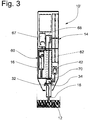
- FIG. 3 A second exemplary embodiment of a mobile water analysis arrangement 10 'is shown, which has an exchangeable cassette 60 which is designed as a drum with 15 compartments 62 for each one test element 16.
- the plastic drum body 64 is axially terminated by respective circular sealing films 66 such that the compartments 62 are gas-tight and liquid-tightly sealed.
- the replaceable cassette 60 is inserted into a corresponding cassette receptacle of the base unit 14 '.
- the base unit 14 ' has a cassette rotary drive 67 and a test element slide drive 68 with a test element slide 70.
- the slider 70 can automatically a test element 16 from a chamber 62 in the in the FIG. 3 push the measuring position shown.
- the slider 70 pushes the test element 16 out of the measuring position and ejects it from the base unit 14 '. Subsequently, the slider 70 is completely pulled out of the cassette 60, whereupon the rotary drive 67, the cassette 60 continues to rotate by a chamber angle, so that the next test element 16 having a chamber 62 is aligned with the slider 70. As soon as the user signals a measurement request, the slider 70 pushes the test element 16 out of the clamp 62 into the measurement position and the measurement can begin.
- the test element 80 is an electrochemical-optical test element that has an electrochemical-optical measuring section 82 in the course of the sample line 84.
- the measuring section 82 two opposing electrodes 86,88 are provided, which are connected via interconnects 90,92 with contacts 94,96.
- the contacts 94,96 face corresponding contacts of the base unit, the latter being connected to the electrochemical meter of the base unit.
- the measuring section 82 has an optical measuring path for a photometer.
- a first reagent section 23 connects to a first reagent 24, which is a main reagent 24.
- a second reagent section 25 connects to a second reagent 27 in the form of a first auxiliary substance 27.
- the second reagent section 25 is followed by a third reagent section 29 with a third reagent 31 in the form of a second auxiliary substance 31.
- the two auxiliary substances 27, 31 are each analyte standards of different amounts or different concentrations.
- test element back is designed as a pump opening 40 pumping element of the test element 80th shown.
- annular sealing element 41 is provided, which surrounds the pump opening 40.
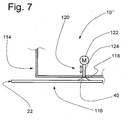
- FIG. 7 3 is a schematic side view of a portion of another embodiment of a mobile water analysis assembly 10 ".
- the water analysis assembly 10" includes a disposable test element 116 having a convex bubble-shaped pumping membrane 118 over the pumping port 40.
- the pumping membrane 118 forming a pumping element includes a volume that is greater than the entire volume of the sample conduit 84.
- the base unit 114 has, as a pump actuator 120, a drive motor 122 and a pump ram 124 driven therefrom, which actuates the pump diaphragm 118 of the inserted disposable test element 116 in a finely dosed manner.
- a test element 16 is first inserted into the test element receptacle of the base unit 14. As a result, if necessary, the base unit 14 is turned on. Thereafter, the inlet port 22 of the test element 16 is manually immersed in the water reservoir 12 to be examined, and pumped by the pump 42, a water sample by forward feeding in the sample line 20 to the measuring section 28. In the measuring section 28, the sample blank value of the water sample is determined with the aid of the measuring device 30 in a first analysis.
- the water sample is conveyed from the measuring section 28 forward into the first reagent section 23.
- the first reagent section 23 abuts the water sample on the first reagent 24 formed as the main reagent, where it mixes with the main reagent.
- the main reagent with the analyte to be detected in the water sample, undergoes a reaction that alters the optical absorption properties of the water sample.
- the determination of the analyte in the water sample can be made considerably more precise.
- the water sample is again conveyed forward to the second reagent section 23, where a second reagent 27 is arranged.
- the second reagent 27 is a first auxiliary substance that forms an analyte standard.
- the water sample mixes with the second reagent 27 in the second reagent section 25.
- the water sample from the second reagent section 25 is conveyed back to the measuring section 82 by backward conveying where the water sample is photometrically analyzed for the third time.
- the water sample is again conveyed forward to the third reagent section 29, where it mixes with the third reagent 31, which is designed as a second auxiliary reagent in the form of a second analyte standard.
- the water sample is again conveyed backwards back to the measuring section 82, where it is analyzed photometrically for the fourth time.
- a concentration-absorption characteristic curve can be generated which allows an accurate determination of the analyte concentration of the water sample from the net analyte measurement.
- the auxiliary reagent may also act as a gelling and / or discoloring agent in the water sample and, after carrying out the quantitative determination of the analyte, be combined with the water sample.
- the discoloration clearly shows that the test element has already been used. If appropriate, this can also be determined by the base unit.
- the gelation fixes the water sample in the sample line 20 and can no longer leak.
- the auxiliary reagent can also be designed as an activator for the main reagent.
- the main reagent and the auxiliary reagent are arranged one behind the other.
- the auxiliary reagent activates the major reagent as it is mixed with the auxiliary reagent in the water sample.
- Both the main reagent and the auxiliary reagent may be disposed between the metering section 28 and the pumping port 40.
Landscapes
- Chemical & Material Sciences (AREA)
- Health & Medical Sciences (AREA)
- Physics & Mathematics (AREA)
- Life Sciences & Earth Sciences (AREA)
- General Health & Medical Sciences (AREA)
- Analytical Chemistry (AREA)
- Pathology (AREA)
- Immunology (AREA)
- Biochemistry (AREA)
- General Physics & Mathematics (AREA)
- Chemical Kinetics & Catalysis (AREA)
- Spectroscopy & Molecular Physics (AREA)
- Engineering & Computer Science (AREA)
- Molecular Biology (AREA)
- Electrochemistry (AREA)
- Food Science & Technology (AREA)
- Medicinal Chemistry (AREA)
- Dispersion Chemistry (AREA)
- Hematology (AREA)
- Clinical Laboratory Science (AREA)
- Toxicology (AREA)
- Plasma & Fusion (AREA)
- Investigating Or Analysing Materials By The Use Of Chemical Reactions (AREA)
- Investigating Or Analyzing Non-Biological Materials By The Use Of Chemical Means (AREA)
Claims (4)
- Procédé d'analyse d'un analyte dans un échantillon d'eau à l'aide d'un dispositif d'analyse d'eau (10) mobile comportant une unité de base (14) mobile et un élément de test (16) jetable inséré dans ladite unité de base (14), ledit élément de test (16) jetable comportant:une conduite à échantillon (20) avec une ouverture d'admission (22) pour recevoir ledit échantillon d'eau, une zone de mesure (28), formant la section de mesure, pour déterminer un analyte dans l'échantillon d'eau et une première zone de réactif (23) située fluidiquement en aval de la zone de mesure (28), vu de l'ouverture d'admission (22), etun réactif (24) disposé dans ladite première zone de réactif (23) dans la conduite à échantillon (20),et ladite unité de base (14) comportant:un logement pour l'élément de test pour retenir ledit élément de test (16) inséré,un appareil de mesure (30) dont la section de mesure est formée par la zone de mesure (28) de l'élément de test, etune pompe (42) ou un actionneur de pompe (120) pour refouler l'échantillon d'eau,le procédé comportant les étapes suivantes:l'insertion de l'élément de test (16) dans ledit logement pour l'élément de test de ladite unité de base (14),le refoulement en avant dudit échantillon d'eau de l'ouverture d'admission (22) jusqu'à la zone de mesure (28), ledit échantillon d'eau arrivant dans la zone de mesure (28) exempte de réactif,une première analyse de l'échantillon d'eau exempte de réactif dans la zone de mesure (28) à l'aide de l'appareil de mesure (30), et la détermination d'une valeur à blanc dudit échantillon,le refoulement en avant dudit échantillon d'eau de la zone de mesure (28) dans la première zone de réactif (23),le refoulement inverse dudit échantillon d'eau de la première zone de réactif (23) dans la zone de mesure (28),une deuxième analyse de l'échantillon d'eau dans la zone de mesure (28) à l'aide de l'appareil de mesure (30), etla soustraction de la valeur à blanc dudit échantillon de la première analyse de la valeur de la deuxième analyse pour obtenir la concentration dudit analyte dans l'échantillon d'eau.
- Procédé selon la revendication 1, dans lequel une deuxième zone de réactif (25) avec un deuxième réactif est disposée au-delà de la première zone de réactif (23), le deuxième réactif étant, de préférence, une substance auxiliaire (27), le procédé comportant l'étape suivante après l'analyse de l'échantillon d'eau:le refoulement en avant dudit échantillon d'eau analysé dans la deuxième zone de réactif (25).
- Procédé selon la revendication 2, avec l'étape suivante après le refoulement en avant dudit échantillon d'eau analysé dans la deuxième zone de réactif (25):le refoulement inverse dudit échantillon d'eau de la deuxième zone de réactif (25) dans la zone de mesure (82), etune troisième analyse de l'échantillon d'eau à l'aide de l'appareil de mesure (30).
- Procédé selon la revendication 3, avec une troisième zone de réactif (29) ayant un troisième réactif (31), disposée en aval de la deuxième zone de réactif (25), le troisième réactif étant, de préférence, uns substance auxiliaire (31), le procédé comportant l'étape suivante après la troisième analyse de l'échantillon d'eau:le refoulement en avant dudit échantillon d'eau analysé dans la troisième zone de réactif (29),le refoulement inverse dudit échantillon d'eau de la troisième zone de réactif (29) dans la zone de mesure (82), etune quatrième analyse de l'échantillon d'eau dans la zone de mesure (82) à l'aide de l'appareil de mesure (30).
Applications Claiming Priority (2)
| Application Number | Priority Date | Filing Date | Title |
|---|---|---|---|
| DE200810050092 DE102008050092A1 (de) | 2008-10-06 | 2008-10-06 | Mobile Wasser-Analyseanordnung |
| PCT/EP2009/062535 WO2010040657A1 (fr) | 2008-10-06 | 2009-09-28 | Procédé d'analyse d'un analyte dans un échantillon d'eau à l'aide d'un dispositif d'analyse d'eau mobile |
Publications (2)
| Publication Number | Publication Date |
|---|---|
| EP2340432A1 EP2340432A1 (fr) | 2011-07-06 |
| EP2340432B1 true EP2340432B1 (fr) | 2017-11-08 |
Family
ID=41435258
Family Applications (2)
| Application Number | Title | Priority Date | Filing Date |
|---|---|---|---|
| EP09783492.3A Active EP2340432B1 (fr) | 2008-10-06 | 2009-09-28 | Procédé d'analyse d'un analyte dans un échantillon d'eau à l'aide d'un dispositif d'analyse d'eau mobile |
| EP09783480.8A Active EP2340431B1 (fr) | 2008-10-06 | 2009-09-28 | Dispositif mobile d'analyse d'eau et procédé de détermination d'un analyte dans un échantillon d'eau |
Family Applications After (1)
| Application Number | Title | Priority Date | Filing Date |
|---|---|---|---|
| EP09783480.8A Active EP2340431B1 (fr) | 2008-10-06 | 2009-09-28 | Dispositif mobile d'analyse d'eau et procédé de détermination d'un analyte dans un échantillon d'eau |
Country Status (5)
| Country | Link |
|---|---|
| US (5) | US9052302B2 (fr) |
| EP (2) | EP2340432B1 (fr) |
| CN (2) | CN102239404B (fr) |
| DE (1) | DE102008050092A1 (fr) |
| WO (2) | WO2010040655A1 (fr) |
Families Citing this family (21)
| Publication number | Priority date | Publication date | Assignee | Title |
|---|---|---|---|---|
| DE102008050092A1 (de) | 2008-10-06 | 2010-04-08 | Hach Lange Gmbh | Mobile Wasser-Analyseanordnung |
| EP3572801A1 (fr) * | 2009-08-25 | 2019-11-27 | Hach Lange GmbH | Appareil d'analyse de processus |
| WO2012011074A2 (fr) * | 2010-07-22 | 2012-01-26 | Hach Company | Laboratoire-sur-puce pour une analyse d'alcalinité |
| US9612230B2 (en) * | 2011-06-21 | 2017-04-04 | Miura Co., Ltd. | Water quality measuring device |
| DE102012102256B4 (de) * | 2012-03-16 | 2024-05-29 | Endress+Hauser Conducta Gmbh+Co. Kg | Analysegerät mit Basismodul und austauschbarer Kassette |
| USD768872S1 (en) * | 2012-12-12 | 2016-10-11 | Hach Company | Cuvette for a water analysis instrument |
| DE102013011495A1 (de) * | 2013-07-02 | 2015-01-08 | Laser- Und Medizin-Technologie Gmbh, Berlin | Verfahren zur Ermittlung der Konzentration eines Stoffes in einem verformbaren Behälter |
| TWI551860B (zh) * | 2015-07-17 | 2016-10-01 | 台欣生物科技研發股份有限公司 | 測試片 |
| JP7034947B2 (ja) * | 2016-06-17 | 2022-03-14 | エフ.ホフマン-ラ ロシュ アーゲー | 体液の試料を分析するための試験システム |
| CN106644973B (zh) * | 2016-10-10 | 2019-08-09 | 宁波市雨辰环保科技有限公司 | 全功能水质在线监测仪 |
| US10479698B2 (en) * | 2016-10-31 | 2019-11-19 | Mohamad Tarek Dajani | System and method for an automated water testing device |
| CN212301316U (zh) * | 2017-07-13 | 2021-01-05 | 福斯分析仪器公司 | 具有除湿器的光学分析仪 |
| DE102018000965A1 (de) | 2018-02-07 | 2019-08-08 | Lilian Labs GmbH | Vorrichtung und Verfahren zur Flüssigkeitsanalyse |
| US11311875B2 (en) | 2018-03-29 | 2022-04-26 | Government Of The United States As Represented By The Administrator Of The U.S. Environmental Protection Agency | Sample device for mobile water analysis |
| NL2021210B1 (en) * | 2018-06-29 | 2020-01-06 | Oasen N V | A mobile system for continuous, automatic, online monitoring of water quality and particle sampling in a drinking water distribution network |
| CN111366725A (zh) * | 2018-12-26 | 2020-07-03 | 台达电子工业股份有限公司 | 增强检测信号的检测方法、装置及试片 |
| US20220193668A1 (en) * | 2019-04-18 | 2022-06-23 | Siemens Healthcare Diagnostics Inc. | Integrated microfluidic device with pipette adaptation |
| EP4127673A4 (fr) * | 2020-03-26 | 2024-07-17 | ORB XYZ, Inc. | Détection d'un analyte dans un milieu |
| EP4256306B1 (fr) | 2020-12-04 | 2025-02-26 | Kofler GmbH | Robot de pipettage pour la détermination d'au moins une caractéristique de l'eau |
| TWI777558B (zh) * | 2021-05-13 | 2022-09-11 | 國立屏東科技大學 | 具備行動通訊的可程式酸鹼值量測系統 |
| CN113252862B (zh) * | 2021-07-14 | 2021-09-17 | 四川久环环境技术有限责任公司 | 一种水质监测站 |
Family Cites Families (34)
| Publication number | Priority date | Publication date | Assignee | Title |
|---|---|---|---|---|
| GB1299363A (en) * | 1968-09-27 | 1972-12-13 | Amiram Ur | Monitoring of chemical, bio-chemical and biological reactions, particularly blood-clotting |
| DE3446756C1 (de) * | 1984-12-21 | 1985-10-31 | Betz, Michael, Dr., 2300 Molfsee | Photometer zum Analysieren fluessiger Medien |
| DE4109118C2 (de) | 1991-03-20 | 1995-04-06 | Lange Gmbh Dr Bruno | Verfahren zum automatischen Auswerten eines Probeninhaltsstoffes einer Wasserprobe |
| US5672319A (en) * | 1993-04-29 | 1997-09-30 | Danfoss A/S | Device for analyzing a fluid medium |
| PL311273A1 (en) * | 1993-04-29 | 1996-02-05 | Danfoss As | Fluid analyser |
| EP0679881B1 (fr) * | 1994-04-27 | 1997-08-20 | Hewlett-Packard GmbH | Détecteur optique |
| US5731212A (en) * | 1994-12-20 | 1998-03-24 | International Technidyne Corporation | Test apparatus and method for testing cuvette accommodated samples |
| US6130098A (en) * | 1995-09-15 | 2000-10-10 | The Regents Of The University Of Michigan | Moving microdroplets |
| DE19535046C2 (de) * | 1995-09-21 | 1998-04-16 | Eppendorf Geraetebau Netheler | Handgerät zum Pipettieren und photometrischen Messen von Proben |
| US5821405A (en) * | 1996-02-29 | 1998-10-13 | Hydrolab Corporation | Modular water quality apparatus and method |
| DE19629835A1 (de) | 1996-07-24 | 1998-01-29 | Abb Patent Gmbh | Vorrichtung zur Analyse von Flüssigkeiten |
| EP0955084B1 (fr) | 1998-04-27 | 2006-07-26 | Corning Incorporated | Procédé pour le dépôt d'échantillons biologiques avec un réservoir capillaire refilé |
| US6521182B1 (en) * | 1998-07-20 | 2003-02-18 | Lifescan, Inc. | Fluidic device for medical diagnostics |
| GB0013125D0 (en) * | 2000-05-31 | 2000-07-19 | Powell Stevens Peter | In car memo/security aid |
| SG100731A1 (en) * | 2000-08-30 | 2003-12-26 | Wardlaw Partners Lp | Container for holding biologic fluid for analysis |
| US8231845B2 (en) * | 2000-10-25 | 2012-07-31 | Steag Microparts | Structures for uniform capillary flow |
| DE10113646A1 (de) | 2001-03-20 | 2002-09-26 | Abb Research Ltd | Vorrichtung zum Untersuchen von Flüssigkeiten |
| DE10222822A1 (de) * | 2002-05-21 | 2003-12-04 | Conducta Endress & Hauser | Online-Analysator |
| US6867857B2 (en) * | 2002-10-29 | 2005-03-15 | Nanostream, Inc. | Flow cell for optical analysis of a fluid |
| US20040154933A1 (en) * | 2003-02-11 | 2004-08-12 | Instrumentation Laboratory Company | Polymeric membranes for use in electrochemical sensors |
| US20050037508A1 (en) | 2003-08-12 | 2005-02-17 | Juan Hernandez | Microfluidic titration apparatus |
| US7459713B2 (en) | 2003-08-14 | 2008-12-02 | Microptix Technologies, Llc | Integrated sensing system approach for handheld spectral measurements having a disposable sample handling apparatus |
| GB2416030B (en) | 2004-01-28 | 2008-07-23 | Norchip As | A diagnostic system for carrying out a nucleic acid sequence amplification and detection process |
| GB2420849B (en) * | 2004-12-02 | 2007-06-27 | Schlumberger Holdings | Optical pH sensor |
| US7491366B2 (en) | 2005-03-03 | 2009-02-17 | Ecolab Inc. | Portable multi-channel device for optically testing a liquid sample |
| EP1739421A1 (fr) * | 2005-06-27 | 2007-01-03 | CLR Srl | Analyseur électrochimique pour la mesure sélective des chlorites dans l'eau |
| KR100680267B1 (ko) | 2005-09-16 | 2007-02-08 | 주식회사 인포피아 | 식별정보를 포함하는 바이오 센서 및 바이오 센서의식별정보 판독장치 |
| US7485153B2 (en) * | 2005-12-27 | 2009-02-03 | Honeywell International Inc. | Fluid free interface for a fluidic analyzer |
| EP1870027A1 (fr) * | 2006-06-21 | 2007-12-26 | Trace Analytics GmbH | Dispositifs et procédés destinés à la détermination d'un analyte |
| US7883898B2 (en) | 2007-05-07 | 2011-02-08 | General Electric Company | Method and apparatus for measuring pH of low alkalinity solutions |
| WO2009119578A1 (fr) | 2008-03-25 | 2009-10-01 | 国立大学法人岡山大学 | Dispositif de distribution de microgouttelettes |
| US20100009336A1 (en) | 2008-07-11 | 2010-01-14 | Sullivan Shannon E | System and method for bacterial vaginosis testing |
| DE102008050092A1 (de) | 2008-10-06 | 2010-04-08 | Hach Lange Gmbh | Mobile Wasser-Analyseanordnung |
| WO2012011074A2 (fr) | 2010-07-22 | 2012-01-26 | Hach Company | Laboratoire-sur-puce pour une analyse d'alcalinité |
-
2008
- 2008-10-06 DE DE200810050092 patent/DE102008050092A1/de not_active Ceased
-
2009
- 2009-09-28 CN CN200980148698.9A patent/CN102239404B/zh active Active
- 2009-09-28 CN CN200980148857.5A patent/CN102239405B/zh active Active
- 2009-09-28 US US13/122,561 patent/US9052302B2/en active Active
- 2009-09-28 EP EP09783492.3A patent/EP2340432B1/fr active Active
- 2009-09-28 EP EP09783480.8A patent/EP2340431B1/fr active Active
- 2009-09-28 WO PCT/EP2009/062521 patent/WO2010040655A1/fr not_active Ceased
- 2009-09-28 US US13/122,560 patent/US9012234B2/en active Active
- 2009-09-28 WO PCT/EP2009/062535 patent/WO2010040657A1/fr not_active Ceased
-
2014
- 2014-02-05 US US14/172,915 patent/US9625435B2/en not_active Expired - Fee Related
-
2015
- 2015-04-30 US US14/700,154 patent/US10261009B2/en active Active
-
2017
- 2017-03-02 US US15/447,138 patent/US10309950B2/en active Active
Non-Patent Citations (1)
| Title |
|---|
| None * |
Also Published As
| Publication number | Publication date |
|---|---|
| US20110223681A1 (en) | 2011-09-15 |
| EP2340431B1 (fr) | 2017-09-06 |
| US20140154138A1 (en) | 2014-06-05 |
| US20110212538A1 (en) | 2011-09-01 |
| CN102239405A (zh) | 2011-11-09 |
| US10261009B2 (en) | 2019-04-16 |
| CN102239404B (zh) | 2015-03-11 |
| US10309950B2 (en) | 2019-06-04 |
| WO2010040655A1 (fr) | 2010-04-15 |
| WO2010040657A1 (fr) | 2010-04-15 |
| US9012234B2 (en) | 2015-04-21 |
| US20150233817A1 (en) | 2015-08-20 |
| US20170176406A1 (en) | 2017-06-22 |
| CN102239405B (zh) | 2014-11-05 |
| US9052302B2 (en) | 2015-06-09 |
| EP2340432A1 (fr) | 2011-07-06 |
| CN102239404A (zh) | 2011-11-09 |
| EP2340431A1 (fr) | 2011-07-06 |
| DE102008050092A1 (de) | 2010-04-08 |
| US9625435B2 (en) | 2017-04-18 |
Similar Documents
| Publication | Publication Date | Title |
|---|---|---|
| EP2340432B1 (fr) | Procédé d'analyse d'un analyte dans un échantillon d'eau à l'aide d'un dispositif d'analyse d'eau mobile | |
| DE102012205171B3 (de) | Integriertes Einweg-Chipkartuschensystem für mobile Multiparameteranalysen chemischer und/oder biologischer Substanzen | |
| EP2062643B1 (fr) | Système d'analyse et procédé d'analyse d'un échantillon de liquide corporel sur un analyte contenu dans celui-ci | |
| DE4029746C2 (fr) | ||
| DE69931469T2 (de) | Vorrichtung zum füllen mittels kapillar-aktion | |
| DE4427725C2 (de) | Meßeinrichtung zur Analyse von Flüssigkeiten | |
| DE19546535C2 (de) | Meßkartusche für flüssige oder gasförmige Proben, Verfahren zu deren Betreiben und deren Verwendung | |
| EP0460343B1 (fr) | Elément de mesure à usage unique pour l'analyse d'un échantillon liquide ou gazeux | |
| DE2128793A1 (de) | Einrichtung für chemische Analysen. | |
| DE2128794A1 (de) | Photometrische Prüfeinrichtung | |
| DE19535046A1 (de) | System zum Pipettieren und photometrischen Messen von Proben | |
| EP2654955A1 (fr) | Procédé de mélange d'au moins une solution d'échantillon avec au moins un réactif et dispositif | |
| DE2610808A1 (de) | Automatisches analysiergeraet | |
| EP0335859B1 (fr) | Dispositif de mesure de composants présents dans un échantillon | |
| DE10035911A1 (de) | Verfahren und Sensor zum Überwachen von Flüssigkeiten | |
| DE4227338A1 (de) | Verfahren und Durchflußmeßanordnung zur Analyse von Flüssigkeiten | |
| DE10113646A1 (de) | Vorrichtung zum Untersuchen von Flüssigkeiten | |
| EP1685388B1 (fr) | Dispositif et procede pour analyser un echantillon liquide | |
| EP0923731A1 (fr) | Dispositif pour loger de fa on interchangeable des cartouches ou des cellules de mesure, pour determiner des parametres de mesure biochimiques dans des systemes d'analyse commandes par ordinateur, et dispositifs associes utilises dans lesdites cartouches ou cellules de mesure | |
| DE2557060C3 (de) | Verfahren und Vorrichtung zur Bestimmung von in Lösung befindlichen Ionen | |
| DE10057895A1 (de) | Vorrichtung und Verfahren zur Probenvorbereitung flüssiger Proben | |
| DE10113628A1 (de) | Vorrichtung zum Untersuchen von Flüssigkeiten | |
| EP4699695A1 (fr) | Cuvette pour l'analyse d'un fluide |
Legal Events
| Date | Code | Title | Description |
|---|---|---|---|
| PUAI | Public reference made under article 153(3) epc to a published international application that has entered the european phase |
Free format text: ORIGINAL CODE: 0009012 |
|
| 17P | Request for examination filed |
Effective date: 20110426 |
|
| AK | Designated contracting states |
Kind code of ref document: A1 Designated state(s): AT BE BG CH CY CZ DE DK EE ES FI FR GB GR HR HU IE IS IT LI LT LU LV MC MK MT NL NO PL PT RO SE SI SK SM TR |
|
| AX | Request for extension of the european patent |
Extension state: AL BA RS |
|
| RIN1 | Information on inventor provided before grant (corrected) |
Inventor name: HUENIG, ISABEL Inventor name: MITREITER, ANDREAS Inventor name: UTHEMANN, ROLF Inventor name: LUNDGREEN, ULRICH Inventor name: LENHARD, MARKUS Inventor name: FROEMEL, RAINER Inventor name: FARJAM, ARIA Inventor name: KUMPCH, HANS-JOACHIM |
|
| DAX | Request for extension of the european patent (deleted) | ||
| 17Q | First examination report despatched |
Effective date: 20160413 |
|
| REG | Reference to a national code |
Ref country code: DE Ref legal event code: R079 Ref document number: 502009014522 Country of ref document: DE Free format text: PREVIOUS MAIN CLASS: G01N0027280000 Ipc: G01N0021310000 |
|
| GRAP | Despatch of communication of intention to grant a patent |
Free format text: ORIGINAL CODE: EPIDOSNIGR1 |
|
| STAA | Information on the status of an ep patent application or granted ep patent |
Free format text: STATUS: GRANT OF PATENT IS INTENDED |
|
| RIC1 | Information provided on ipc code assigned before grant |
Ipc: G01N 27/28 20060101ALI20170531BHEP Ipc: G01N 33/18 20060101ALI20170531BHEP Ipc: G01N 21/31 20060101AFI20170531BHEP Ipc: B01L 3/00 20060101ALN20170531BHEP Ipc: G01N 27/403 20060101ALI20170531BHEP |
|
| INTG | Intention to grant announced |
Effective date: 20170705 |
|
| RAP1 | Party data changed (applicant data changed or rights of an application transferred) |
Owner name: HACH LANGE GMBH |
|
| GRAS | Grant fee paid |
Free format text: ORIGINAL CODE: EPIDOSNIGR3 |
|
| GRAA | (expected) grant |
Free format text: ORIGINAL CODE: 0009210 |
|
| STAA | Information on the status of an ep patent application or granted ep patent |
Free format text: STATUS: THE PATENT HAS BEEN GRANTED |
|
| AK | Designated contracting states |
Kind code of ref document: B1 Designated state(s): AT BE BG CH CY CZ DE DK EE ES FI FR GB GR HR HU IE IS IT LI LT LU LV MC MK MT NL NO PL PT RO SE SI SK SM TR |
|
| REG | Reference to a national code |
Ref country code: GB Ref legal event code: FG4D Free format text: NOT ENGLISH |
|
| REG | Reference to a national code |
Ref country code: CH Ref legal event code: EP Ref country code: AT Ref legal event code: REF Ref document number: 944597 Country of ref document: AT Kind code of ref document: T Effective date: 20171115 |
|
| REG | Reference to a national code |
Ref country code: IE Ref legal event code: FG4D Free format text: LANGUAGE OF EP DOCUMENT: GERMAN |
|
| REG | Reference to a national code |
Ref country code: DE Ref legal event code: R096 Ref document number: 502009014522 Country of ref document: DE |
|
| REG | Reference to a national code |
Ref country code: NL Ref legal event code: MP Effective date: 20171108 |
|
| REG | Reference to a national code |
Ref country code: LT Ref legal event code: MG4D |
|
| PG25 | Lapsed in a contracting state [announced via postgrant information from national office to epo] |
Ref country code: ES Free format text: LAPSE BECAUSE OF FAILURE TO SUBMIT A TRANSLATION OF THE DESCRIPTION OR TO PAY THE FEE WITHIN THE PRESCRIBED TIME-LIMIT Effective date: 20171108 Ref country code: SE Free format text: LAPSE BECAUSE OF FAILURE TO SUBMIT A TRANSLATION OF THE DESCRIPTION OR TO PAY THE FEE WITHIN THE PRESCRIBED TIME-LIMIT Effective date: 20171108 Ref country code: FI Free format text: LAPSE BECAUSE OF FAILURE TO SUBMIT A TRANSLATION OF THE DESCRIPTION OR TO PAY THE FEE WITHIN THE PRESCRIBED TIME-LIMIT Effective date: 20171108 Ref country code: LT Free format text: LAPSE BECAUSE OF FAILURE TO SUBMIT A TRANSLATION OF THE DESCRIPTION OR TO PAY THE FEE WITHIN THE PRESCRIBED TIME-LIMIT Effective date: 20171108 Ref country code: NO Free format text: LAPSE BECAUSE OF FAILURE TO SUBMIT A TRANSLATION OF THE DESCRIPTION OR TO PAY THE FEE WITHIN THE PRESCRIBED TIME-LIMIT Effective date: 20180208 Ref country code: NL Free format text: LAPSE BECAUSE OF FAILURE TO SUBMIT A TRANSLATION OF THE DESCRIPTION OR TO PAY THE FEE WITHIN THE PRESCRIBED TIME-LIMIT Effective date: 20171108 |
|
| PG25 | Lapsed in a contracting state [announced via postgrant information from national office to epo] |
Ref country code: GR Free format text: LAPSE BECAUSE OF FAILURE TO SUBMIT A TRANSLATION OF THE DESCRIPTION OR TO PAY THE FEE WITHIN THE PRESCRIBED TIME-LIMIT Effective date: 20180209 Ref country code: HR Free format text: LAPSE BECAUSE OF FAILURE TO SUBMIT A TRANSLATION OF THE DESCRIPTION OR TO PAY THE FEE WITHIN THE PRESCRIBED TIME-LIMIT Effective date: 20171108 Ref country code: LV Free format text: LAPSE BECAUSE OF FAILURE TO SUBMIT A TRANSLATION OF THE DESCRIPTION OR TO PAY THE FEE WITHIN THE PRESCRIBED TIME-LIMIT Effective date: 20171108 Ref country code: IS Free format text: LAPSE BECAUSE OF FAILURE TO SUBMIT A TRANSLATION OF THE DESCRIPTION OR TO PAY THE FEE WITHIN THE PRESCRIBED TIME-LIMIT Effective date: 20180308 Ref country code: BG Free format text: LAPSE BECAUSE OF FAILURE TO SUBMIT A TRANSLATION OF THE DESCRIPTION OR TO PAY THE FEE WITHIN THE PRESCRIBED TIME-LIMIT Effective date: 20180208 |
|
| PG25 | Lapsed in a contracting state [announced via postgrant information from national office to epo] |
Ref country code: CZ Free format text: LAPSE BECAUSE OF FAILURE TO SUBMIT A TRANSLATION OF THE DESCRIPTION OR TO PAY THE FEE WITHIN THE PRESCRIBED TIME-LIMIT Effective date: 20171108 Ref country code: CY Free format text: LAPSE BECAUSE OF FAILURE TO SUBMIT A TRANSLATION OF THE DESCRIPTION OR TO PAY THE FEE WITHIN THE PRESCRIBED TIME-LIMIT Effective date: 20171108 Ref country code: EE Free format text: LAPSE BECAUSE OF FAILURE TO SUBMIT A TRANSLATION OF THE DESCRIPTION OR TO PAY THE FEE WITHIN THE PRESCRIBED TIME-LIMIT Effective date: 20171108 Ref country code: DK Free format text: LAPSE BECAUSE OF FAILURE TO SUBMIT A TRANSLATION OF THE DESCRIPTION OR TO PAY THE FEE WITHIN THE PRESCRIBED TIME-LIMIT Effective date: 20171108 Ref country code: SK Free format text: LAPSE BECAUSE OF FAILURE TO SUBMIT A TRANSLATION OF THE DESCRIPTION OR TO PAY THE FEE WITHIN THE PRESCRIBED TIME-LIMIT Effective date: 20171108 |
|
| REG | Reference to a national code |
Ref country code: DE Ref legal event code: R097 Ref document number: 502009014522 Country of ref document: DE |
|
| PG25 | Lapsed in a contracting state [announced via postgrant information from national office to epo] |
Ref country code: IT Free format text: LAPSE BECAUSE OF FAILURE TO SUBMIT A TRANSLATION OF THE DESCRIPTION OR TO PAY THE FEE WITHIN THE PRESCRIBED TIME-LIMIT Effective date: 20171108 Ref country code: RO Free format text: LAPSE BECAUSE OF FAILURE TO SUBMIT A TRANSLATION OF THE DESCRIPTION OR TO PAY THE FEE WITHIN THE PRESCRIBED TIME-LIMIT Effective date: 20171108 Ref country code: SM Free format text: LAPSE BECAUSE OF FAILURE TO SUBMIT A TRANSLATION OF THE DESCRIPTION OR TO PAY THE FEE WITHIN THE PRESCRIBED TIME-LIMIT Effective date: 20171108 Ref country code: PL Free format text: LAPSE BECAUSE OF FAILURE TO SUBMIT A TRANSLATION OF THE DESCRIPTION OR TO PAY THE FEE WITHIN THE PRESCRIBED TIME-LIMIT Effective date: 20171108 |
|
| PLBE | No opposition filed within time limit |
Free format text: ORIGINAL CODE: 0009261 |
|
| STAA | Information on the status of an ep patent application or granted ep patent |
Free format text: STATUS: NO OPPOSITION FILED WITHIN TIME LIMIT |
|
| REG | Reference to a national code |
Ref country code: FR Ref legal event code: PLFP Year of fee payment: 10 |
|
| PG25 | Lapsed in a contracting state [announced via postgrant information from national office to epo] |
Ref country code: MT Free format text: LAPSE BECAUSE OF FAILURE TO SUBMIT A TRANSLATION OF THE DESCRIPTION OR TO PAY THE FEE WITHIN THE PRESCRIBED TIME-LIMIT Effective date: 20171108 |
|
| 26N | No opposition filed |
Effective date: 20180809 |
|
| PG25 | Lapsed in a contracting state [announced via postgrant information from national office to epo] |
Ref country code: SI Free format text: LAPSE BECAUSE OF FAILURE TO SUBMIT A TRANSLATION OF THE DESCRIPTION OR TO PAY THE FEE WITHIN THE PRESCRIBED TIME-LIMIT Effective date: 20171108 |
|
| PG25 | Lapsed in a contracting state [announced via postgrant information from national office to epo] |
Ref country code: MC Free format text: LAPSE BECAUSE OF FAILURE TO SUBMIT A TRANSLATION OF THE DESCRIPTION OR TO PAY THE FEE WITHIN THE PRESCRIBED TIME-LIMIT Effective date: 20171108 |
|
| REG | Reference to a national code |
Ref country code: CH Ref legal event code: PL |
|
| REG | Reference to a national code |
Ref country code: BE Ref legal event code: MM Effective date: 20180930 |
|
| REG | Reference to a national code |
Ref country code: IE Ref legal event code: MM4A |
|
| PG25 | Lapsed in a contracting state [announced via postgrant information from national office to epo] |
Ref country code: LU Free format text: LAPSE BECAUSE OF NON-PAYMENT OF DUE FEES Effective date: 20180928 |
|
| PG25 | Lapsed in a contracting state [announced via postgrant information from national office to epo] |
Ref country code: IE Free format text: LAPSE BECAUSE OF NON-PAYMENT OF DUE FEES Effective date: 20180928 |
|
| PG25 | Lapsed in a contracting state [announced via postgrant information from national office to epo] |
Ref country code: BE Free format text: LAPSE BECAUSE OF NON-PAYMENT OF DUE FEES Effective date: 20180930 Ref country code: CH Free format text: LAPSE BECAUSE OF NON-PAYMENT OF DUE FEES Effective date: 20180930 Ref country code: LI Free format text: LAPSE BECAUSE OF NON-PAYMENT OF DUE FEES Effective date: 20180930 |
|
| REG | Reference to a national code |
Ref country code: AT Ref legal event code: MM01 Ref document number: 944597 Country of ref document: AT Kind code of ref document: T Effective date: 20180928 |
|
| PG25 | Lapsed in a contracting state [announced via postgrant information from national office to epo] |
Ref country code: AT Free format text: LAPSE BECAUSE OF NON-PAYMENT OF DUE FEES Effective date: 20180928 |
|
| REG | Reference to a national code |
Ref country code: DE Ref legal event code: R082 Ref document number: 502009014522 Country of ref document: DE Representative=s name: TERPATENT PARTGMBB, DE Ref country code: DE Ref legal event code: R082 Ref document number: 502009014522 Country of ref document: DE Representative=s name: TERPATENT PATENTANWAELTE TER SMITTEN EBERLEIN-, DE |
|
| PG25 | Lapsed in a contracting state [announced via postgrant information from national office to epo] |
Ref country code: TR Free format text: LAPSE BECAUSE OF FAILURE TO SUBMIT A TRANSLATION OF THE DESCRIPTION OR TO PAY THE FEE WITHIN THE PRESCRIBED TIME-LIMIT Effective date: 20171108 |
|
| PG25 | Lapsed in a contracting state [announced via postgrant information from national office to epo] |
Ref country code: PT Free format text: LAPSE BECAUSE OF FAILURE TO SUBMIT A TRANSLATION OF THE DESCRIPTION OR TO PAY THE FEE WITHIN THE PRESCRIBED TIME-LIMIT Effective date: 20171108 Ref country code: HU Free format text: LAPSE BECAUSE OF FAILURE TO SUBMIT A TRANSLATION OF THE DESCRIPTION OR TO PAY THE FEE WITHIN THE PRESCRIBED TIME-LIMIT; INVALID AB INITIO Effective date: 20090928 |
|
| PG25 | Lapsed in a contracting state [announced via postgrant information from national office to epo] |
Ref country code: MK Free format text: LAPSE BECAUSE OF NON-PAYMENT OF DUE FEES Effective date: 20171108 |
|
| PGFP | Annual fee paid to national office [announced via postgrant information from national office to epo] |
Ref country code: DE Payment date: 20250919 Year of fee payment: 17 |
|
| PGFP | Annual fee paid to national office [announced via postgrant information from national office to epo] |
Ref country code: GB Payment date: 20250918 Year of fee payment: 17 |
|
| PGFP | Annual fee paid to national office [announced via postgrant information from national office to epo] |
Ref country code: FR Payment date: 20250922 Year of fee payment: 17 |