EP2340603B1 - Modulation de largeur d impulsion prédictive pour machine à aimants permanents sans fer à haut rendement excitée pour un pont en h à triangle ouvert - Google Patents
Modulation de largeur d impulsion prédictive pour machine à aimants permanents sans fer à haut rendement excitée pour un pont en h à triangle ouvert Download PDFInfo
- Publication number
- EP2340603B1 EP2340603B1 EP09816816.4A EP09816816A EP2340603B1 EP 2340603 B1 EP2340603 B1 EP 2340603B1 EP 09816816 A EP09816816 A EP 09816816A EP 2340603 B1 EP2340603 B1 EP 2340603B1
- Authority
- EP
- European Patent Office
- Prior art keywords
- pulse width
- width modulation
- duty cycle
- machine
- elect
- Prior art date
- Legal status (The legal status is an assumption and is not a legal conclusion. Google has not performed a legal analysis and makes no representation as to the accuracy of the status listed.)
- Active
Links
Images




Classifications
-
- F—MECHANICAL ENGINEERING; LIGHTING; HEATING; WEAPONS; BLASTING
- F02—COMBUSTION ENGINES; HOT-GAS OR COMBUSTION-PRODUCT ENGINE PLANTS
- F02D—CONTROLLING COMBUSTION ENGINES
- F02D41/00—Electrical control of supply of combustible mixture or its constituents
- F02D41/20—Output circuits, e.g. for controlling currents in command coils
-
- H—ELECTRICITY
- H02—GENERATION; CONVERSION OR DISTRIBUTION OF ELECTRIC POWER
- H02P—CONTROL OR REGULATION OF ELECTRIC MOTORS, ELECTRIC GENERATORS OR DYNAMO-ELECTRIC CONVERTERS; CONTROLLING TRANSFORMERS, REACTORS OR CHOKE COILS
- H02P21/00—Arrangements or methods for the control of electric machines by vector control, e.g. by control of field orientation
-
- G—PHYSICS
- G05—CONTROLLING; REGULATING
- G05B—CONTROL OR REGULATING SYSTEMS IN GENERAL; FUNCTIONAL ELEMENTS OF SUCH SYSTEMS; MONITORING OR TESTING ARRANGEMENTS FOR SUCH SYSTEMS OR ELEMENTS
- G05B11/00—Automatic controllers
- G05B11/01—Automatic controllers electric
- G05B11/26—Automatic controllers electric in which the output signal is a pulse-train
- G05B11/28—Automatic controllers electric in which the output signal is a pulse-train using pulse-height modulation; using pulse-width modulation
-
- H—ELECTRICITY
- H02—GENERATION; CONVERSION OR DISTRIBUTION OF ELECTRIC POWER
- H02P—CONTROL OR REGULATION OF ELECTRIC MOTORS, ELECTRIC GENERATORS OR DYNAMO-ELECTRIC CONVERTERS; CONTROLLING TRANSFORMERS, REACTORS OR CHOKE COILS
- H02P23/00—Arrangements or methods for the control of AC motors characterised by a control method other than vector control
- H02P23/14—Estimation or adaptation of motor parameters, e.g. rotor time constant, flux, speed, current or voltage
-
- H—ELECTRICITY
- H02—GENERATION; CONVERSION OR DISTRIBUTION OF ELECTRIC POWER
- H02P—CONTROL OR REGULATION OF ELECTRIC MOTORS, ELECTRIC GENERATORS OR DYNAMO-ELECTRIC CONVERTERS; CONTROLLING TRANSFORMERS, REACTORS OR CHOKE COILS
- H02P27/00—Arrangements or methods for the control of AC motors characterised by the kind of supply voltage
- H02P27/04—Arrangements or methods for the control of AC motors characterised by the kind of supply voltage using variable-frequency supply voltage, e.g. inverter or converter supply voltage
- H02P27/06—Arrangements or methods for the control of AC motors characterised by the kind of supply voltage using variable-frequency supply voltage, e.g. inverter or converter supply voltage using DC to AC converters or inverters
- H02P27/08—Arrangements or methods for the control of AC motors characterised by the kind of supply voltage using variable-frequency supply voltage, e.g. inverter or converter supply voltage using DC to AC converters or inverters with pulse width modulation
-
- F—MECHANICAL ENGINEERING; LIGHTING; HEATING; WEAPONS; BLASTING
- F02—COMBUSTION ENGINES; HOT-GAS OR COMBUSTION-PRODUCT ENGINE PLANTS
- F02D—CONTROLLING COMBUSTION ENGINES
- F02D41/00—Electrical control of supply of combustible mixture or its constituents
- F02D41/20—Output circuits, e.g. for controlling currents in command coils
- F02D2041/202—Output circuits, e.g. for controlling currents in command coils characterised by the control of the circuit
- F02D2041/2024—Output circuits, e.g. for controlling currents in command coils characterised by the control of the circuit the control switching a load after time-on and time-off pulses
- F02D2041/2027—Control of the current by pulse width modulation or duty cycle control
-
- F—MECHANICAL ENGINEERING; LIGHTING; HEATING; WEAPONS; BLASTING
- F02—COMBUSTION ENGINES; HOT-GAS OR COMBUSTION-PRODUCT ENGINE PLANTS
- F02D—CONTROLLING COMBUSTION ENGINES
- F02D41/00—Electrical control of supply of combustible mixture or its constituents
- F02D41/20—Output circuits, e.g. for controlling currents in command coils
- F02D2041/202—Output circuits, e.g. for controlling currents in command coils characterised by the control of the circuit
- F02D2041/2051—Output circuits, e.g. for controlling currents in command coils characterised by the control of the circuit using voltage control
-
- F—MECHANICAL ENGINEERING; LIGHTING; HEATING; WEAPONS; BLASTING
- F02—COMBUSTION ENGINES; HOT-GAS OR COMBUSTION-PRODUCT ENGINE PLANTS
- F02D—CONTROLLING COMBUSTION ENGINES
- F02D41/00—Electrical control of supply of combustible mixture or its constituents
- F02D41/20—Output circuits, e.g. for controlling currents in command coils
- F02D2041/202—Output circuits, e.g. for controlling currents in command coils characterised by the control of the circuit
- F02D2041/2058—Output circuits, e.g. for controlling currents in command coils characterised by the control of the circuit using information of the actual current value
Definitions
- This disclosure relates to a method and system that makes use of the availability of the machine parameters required to achieve optimal selection of pulse width modulation polarity and type. More specifically, the disclosure relates to a method and system that uses a predictive duty cycle employing machine parameters to determine both the magnitude and the pulse width of the pulse width modulation that is required to generate a waveform at a given operation condition, as well as the polarity of the pulse width modulation.
- a permanent magnet machine is a type of alternating current (AC) motor whereby power is supplied to the rotating device by means of imposing an electromagnetic field onto a field generated by a permanent magnet rotor.
- AC alternating current
- PM rotor permanent magnets
- the magnet's position is important for determining the stator current magnitude of the machine necessary to produce the desired torque. This operation is known as the stator current commutation. Since magnets are rotating with respect to the stator, the magnet position can be calculated by measuring the rotor absolute angular position. Absolute position sensors such as resolvers and optical encoders are typically used to measure the absolute angular position of the machine rotor.
- H-bridge topologies are commonly used to drive open delta permanent magnet machines, as well as other types of machines.
- An H-bridge is an electronic circuit which enables a voltage to be applied across a load in either direction.
- the term "H-bridge" is derived from the typical graphical representation of such a circuit as seen in FIG. 1A .
- An H-bridge is built with four switches, which may be solid-state or mechanical. As seen in FIG. 1B , when switches S1 and S4 are closed, and switches S2 and S3 are open, a positive voltage will be applied across the motor. However, by opening switches S1 and S4, and closing switches S2 and S3 ( FIG. 1C ), this voltage is reversed allowing reverse operation of the motor.
- An H-bridge arrangement may be used to reverse the polarity of the motor, but may also be used to stop the motor if the motor's terminals are shorted.
- One of the main benefits for using an H-bridge to drive a PM machine is that it lowers the ripple current in the motor windings that results from the pulsating voltage waveforms of the pulse modulated power stage. Ripple current is a small unwanted residual periodic variation of the direct current output of a power supply which has been derived from an alternating power source.
- Another benefit garnered from driving a PM machine with an H-bridge is that the H-bridge allows a greater level of flexibility to shape the current waveform beyond the 120-degree limitation imposed by a conventional 3-phase inverter.
- unipolar pulse width modulation PWM
- a 50% reduction in ripple current is achieved when compared to bipolar PWM.
- a combination of unipolar and bipolar PWM must be employed; otherwise, current distortion will result.
- the existing prior art merely selects unipolar verses bipolar PWM based upon the sign of the current waveform. This conventional approach leads to additional harmonics in the current waveform that will lead to increased heating in the machine.
- the present method and system optimizes the pulse width modulation generation by appropriately determining when unipolar or bipolar PWM should be used, by exploiting the machine temperature measurements, machine parameters, operation conditions, and the dynamic model of the machine windings.
- Embodiments of the present disclosure relate to a computer-implemented method for determining a predictive duty cycle that is able to determine the magnitude and pulse width of an H-bridge pulse width modulation that is used to drive a machine motor, including determining machine parameters, inputting the machine parameters into a predicted duty cycle module, determining the optimum polarity of the pulse width modulation for a predicted duty cycle based on a pulse width modulation generation algorithm, and determining the optimum type of the pulse width modulation for a predicted duty cycle based on the pulse width modulation generation algorithm.
- the embodiments of the present disclosure relate to a system for determining a predictive duty cycle that is able to determine the magnitude and pulse width of an H-bridge pulse width modulation that is used to drive a machine motor, including means for determining machine parameters, means for inputting the machine parameters into a predicted duty cycle module, means for determining the optimum polarity of the pulse width modulation for a predicted duty cycle based on a pulse width modulation generation algorithm; and means for determining the optimum type of the pulse width modulation for a predicted duty cycle based on the pulse width modulation generation algorithm.
- the embodiments of the present disclosure further relate to a computer-readable medium for determining a predictive duty cycle that is able to determine the magnitude and pulse width of an H-bridge pulse width modulation that is used to drive a machine motor, including means for determining machine parameters, means for inputting the machine parameters into a predicted duty cycle module, means for determining the optimum polarity of the pulse width modulation for a predicted duty cycle based on a pulse width modulation generation algorithm; and means for determining the optimum type of the pulse width modulation for a predicted duty cycle based on the pulse width modulation generation algorithm.
- Applicants have discovered a method and system to optimize the pulse width modulation generation by appropriately determining when a unipolar verses a bipolar pulse width modulation should be used. Moreover, the present method and system uses a predictive method to determine when bipolar verses unipolar PWM should be used, and this prediction is based on factors such as machine temperature measurements, machine parameters, operation conditions, and the dynamic model of the machine windings.
- the motor/generator of the present method and system includes, among other things, ironless rotor magnets 202, 204, as well as a stator 206.
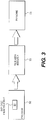
- FIG. 3 illustrates a block diagram of one embodiment of the present invention, including a processor 302 with a duty cycle prediction module 304 which sends information to a pulse width modulator 306.
- the pulse width modulator 306 switches the pulse for a permanent magnet machine 308.
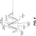
- FIG. 4 illustrates a graphical representation of a duty cycle with respect to one embodiment of the present method and system.
- FIG. 4 depicts, by way of example, when a duty cycle is unipolar and how the machine and processor determines when unipolar positive pulses verses unipolar negative pulses are used in the duty cycle.
- This graphical representation also shows the transition periods when the machine emf voltage has a different polarity from the terminal voltage, and a combination of unipolar and bipolar pulse width modulation must be should be applied to avoid current distortion.
- FIG. 5A illustrates a 3-phase open delta configuration machine model that includes schematic representations for three power sources E a , E b , and E c , three resistors R a , R b , and R c , and three inductors L a , L b , and L c , although other configurations are contemplated.
- the currents i a , i b , and i c of each of the phases are also depicted in the machine model seen in FIG. 5A .
- the machine model is considered an open delta configuration since the three windings are not all connected to one point. The machine is able to receive digital-signals which dictate the motor's movement.
- the motor is started spinning by the motor setting the current vector to a very high DC magnitude. Setting the current vector to a high constant value enables the magnetic field vector of the motor to align itself with the current vector. At this initial time, the torque angle of the motor is near zero.
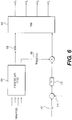
- FIG. 5B is an expanded view of a terminal of the machine, depicting a terminal being driven by an H-bridge at a power stage 504.
- the power stage 504 includes the four switches S 1 , S 2 , S 3 , S 4 of the H-bridge.
- the machine is said to have 6-switching poles since the motor has 3 phases.
- FIG. 4B also depicts the supply voltage Vbus and a capacitor C.
- d predictive The sign (+ or -) of the output of the algorithm, d predictive , delineated above will determine which of the switching poles needs to be switched.
- d predictive is a positive value then the pulse width modulation is unipolar positive, thus switching S1 and S2 on while maintaining S4 on and S3 off will drive a current in the positive direction.
- d predictive is a negative value, the pulse width modulation is unipolar negative, thus switching S3 and S4 on while maintaining S2 on and S1 off will drive a current in the negative direction.
- the algorithm is able to determine the sign 606 of the predictive duty cycle, as well as the value of d predictive 608, which determines the polarity of the duty cycle.
- the processor determines a predicted duty cycle such that the PI regulator 610 is limited in the amount of current correction that it implements, i.e., such that the actual current 614 in the motor is close to the reference current 612 that the processor wants to get out of that particular duty cycle. This reduces the ripple current of the machine and consequently the machine motor runs more efficiently.
- FIG. 7 illustrates a flowchart for optimizing the torque of a permanent magnet machine in one embodiment of the present method and system.
- machine parameters are determined. These parameters may be values known prior to the operation of the machine, and/or they may be parameters that are measured during the operation of the machine.
- the machine parameters are input into a duty cycle prediction module.
- the optimum polarity of the pulse width modulation is determined for a predicted duty cycle based on a pulse width modulation generation algorithm, which is the equation described above, in step 706.
- the optimum type of pulse width modulation is determined for a predicted duty cycle based on a pulse width modulation generation algorithm.
Landscapes
- Engineering & Computer Science (AREA)
- Power Engineering (AREA)
- Physics & Mathematics (AREA)
- General Physics & Mathematics (AREA)
- Automation & Control Theory (AREA)
- Chemical & Material Sciences (AREA)
- Combustion & Propulsion (AREA)
- Mechanical Engineering (AREA)
- General Engineering & Computer Science (AREA)
- Control Of Motors That Do Not Use Commutators (AREA)
- Control Of Ac Motors In General (AREA)
- Control Of Direct Current Motors (AREA)
Claims (3)
- Procédé de détermination d'un cycle de service prédictif qui est capable de déterminer la grandeur et la largeur d'impulsion d'une modulation de largeur d'impulsion de pont en H qui est utilisée pour entraîner un moteur de machine, comprenant :la détermination d'un ou de plusieurs paramètres de machine ;l'entrée des paramètres de machine dans un module de cycle de service prédit ;la détermination de la polarité optimale de la modulation de largeur d'impulsion pour un cycle de service prédit d'après un algorithme de génération de modulation de largeur d'impulsion; etla détermination permettant de savoir si la modulation de largeur d'impulsion est monopolaire ou bipolaire pour un cycle de service prédit d'après l'algorithme de génération de modulation de largeur d'impulsion, dans lequel l'algorithme de génération de modulation de largeur d'impulsion est

- Système de détermination d'un cycle de service prédictif qui est capable de déterminer la grandeur et de largeur d'impulsion d'une modulation de largeur d'impulsion de pont en H qui est utilisée pour entraîner un moteur de machine, comprenant :des moyens pour déterminer un ou plusieurs paramètres de machine ;des moyens pour entrer les paramètres de machine dans un module de cycle de service prédit ;des moyens pour déterminer la polarité optimale de la modulation de largeur d'impulsion pour un cycle de service prédit d'après un algorithme de génération de modulation de largeur d'impulsion; etdes moyens pour déterminer si la modulation de largeur d'impulsion en largeur est monopolaire ou bipolaire pour un cycle de service prédit d'après l'algorithme de génération de modulation de largeur d'impulsion, dans lequel l'algorithme de génération de modulation de largeur d'impulsion est

- Support lisible par ordinateur comprenant des instructions pour une exécution sur un processeur qui, lorsqu'elles sont exécutées par le processeur, amènent le processeur à réaliser le procédé selon la revendication 1 pour déterminer un cycle de service prédictif qui est capable de déterminer la grandeur et la largeur d'impulsion d'une modulation de largeur d'impulsion de pont en H qui est utilisée pour entraîner un moteur de machine, comprenant :des moyens pour déterminer un ou plusieurs paramètres de machine ;des moyens pour entrer les paramètres de machine dans un module de cycle de service prédit ; etdes moyens pour déterminer la polarité optimale de la modulation de largeur d'impulsion pour un cycle de service prédit d'après un algorithme de génération de modulation de largeur d'impulsion ; etdes moyens pour déterminer si la modulation de largeur d'impulsion est monopolaire ou bipolaire pour un cycle de service prédit d'après l'algorithme de génération de modulation de largeur d'impulsion, dans lequel l'algorithme de génération de modulation de largeur d'impulsion est

Priority Applications (1)
| Application Number | Priority Date | Filing Date | Title |
|---|---|---|---|
| EP20157527.1A EP3736954B1 (fr) | 2008-09-23 | 2009-09-23 | Modulation prédictive de largeur d'impulsion pour une machine à aimant permanent, sans fer, à haute efficacité, alimentée par un pont en h en triangle ouvert |
Applications Claiming Priority (2)
| Application Number | Priority Date | Filing Date | Title |
|---|---|---|---|
| US19410208P | 2008-09-23 | 2008-09-23 | |
| PCT/US2009/058117 WO2010036742A1 (fr) | 2008-09-23 | 2009-09-23 | Modulation de largeur d’impulsion prédictive pour machine à aimants permanents sans fer à haut rendement excitée pour un pont en h à triangle ouvert |
Related Child Applications (2)
| Application Number | Title | Priority Date | Filing Date |
|---|---|---|---|
| EP20157527.1A Division EP3736954B1 (fr) | 2008-09-23 | 2009-09-23 | Modulation prédictive de largeur d'impulsion pour une machine à aimant permanent, sans fer, à haute efficacité, alimentée par un pont en h en triangle ouvert |
| EP20157527.1A Division-Into EP3736954B1 (fr) | 2008-09-23 | 2009-09-23 | Modulation prédictive de largeur d'impulsion pour une machine à aimant permanent, sans fer, à haute efficacité, alimentée par un pont en h en triangle ouvert |
Publications (3)
| Publication Number | Publication Date |
|---|---|
| EP2340603A1 EP2340603A1 (fr) | 2011-07-06 |
| EP2340603A4 EP2340603A4 (fr) | 2017-11-22 |
| EP2340603B1 true EP2340603B1 (fr) | 2020-04-08 |
Family
ID=42060071
Family Applications (2)
| Application Number | Title | Priority Date | Filing Date |
|---|---|---|---|
| EP09816816.4A Active EP2340603B1 (fr) | 2008-09-23 | 2009-09-23 | Modulation de largeur d impulsion prédictive pour machine à aimants permanents sans fer à haut rendement excitée pour un pont en h à triangle ouvert |
| EP20157527.1A Active EP3736954B1 (fr) | 2008-09-23 | 2009-09-23 | Modulation prédictive de largeur d'impulsion pour une machine à aimant permanent, sans fer, à haute efficacité, alimentée par un pont en h en triangle ouvert |
Family Applications After (1)
| Application Number | Title | Priority Date | Filing Date |
|---|---|---|---|
| EP20157527.1A Active EP3736954B1 (fr) | 2008-09-23 | 2009-09-23 | Modulation prédictive de largeur d'impulsion pour une machine à aimant permanent, sans fer, à haute efficacité, alimentée par un pont en h en triangle ouvert |
Country Status (8)
| Country | Link |
|---|---|
| US (3) | US8242731B2 (fr) |
| EP (2) | EP2340603B1 (fr) |
| JP (1) | JP5411278B2 (fr) |
| KR (1) | KR101246049B1 (fr) |
| CN (1) | CN102224664A (fr) |
| AU (1) | AU2009296683B2 (fr) |
| CA (1) | CA2740401C (fr) |
| WO (1) | WO2010036742A1 (fr) |
Families Citing this family (9)
| Publication number | Priority date | Publication date | Assignee | Title |
|---|---|---|---|---|
| EP2340603B1 (fr) | 2008-09-23 | 2020-04-08 | Aerovironment inc. | Modulation de largeur d impulsion prédictive pour machine à aimants permanents sans fer à haut rendement excitée pour un pont en h à triangle ouvert |
| KR101244299B1 (ko) | 2008-09-23 | 2013-03-18 | 에어로바이론먼트 인크 | 무철심형 영구 자석 기계의 센서리스 토크 제어 방법 및 시스템 |
| FR2993093B1 (fr) * | 2012-07-03 | 2014-06-20 | Valeo Sys Controle Moteur Sas | Circuit electrique pour l'excitation d'au moins un electro-aimant |
| CN103743966B (zh) * | 2013-11-26 | 2017-01-18 | 广东威灵电机制造有限公司 | 一种电机驱动装置中pwm模块的检测方法和系统 |
| KR102227416B1 (ko) * | 2013-12-18 | 2021-03-12 | 오티스 엘리베이터 컴파니 | 다중레벨 회생 드라이브를 위한 pwm 전략 |
| CN104578149B (zh) * | 2014-12-23 | 2017-05-17 | 天津大学 | 双馈风力发电系统网侧变换器预测占空比控制方法 |
| WO2019235655A1 (fr) * | 2018-06-05 | 2019-12-12 | 숭실대학교산학협력단 | Onduleur multiphase utilisant un pont en h multiple indépendant |
| CN109039189B (zh) * | 2018-07-17 | 2021-11-26 | 东南大学 | 基于几何法的永磁同步电机两矢量预测控制方法 |
| CN109149936B (zh) * | 2018-09-12 | 2020-06-26 | 西安理工大学 | 一种适用dc/dc变换器的占空比预测控制系统及控制算法 |
Family Cites Families (72)
| Publication number | Priority date | Publication date | Assignee | Title |
|---|---|---|---|---|
| US4332464A (en) * | 1980-09-22 | 1982-06-01 | Xerox Corporation | Interactive user-machine interface method and apparatus for copier/duplicator |
| US4698625A (en) * | 1985-05-30 | 1987-10-06 | International Business Machines Corp. | Graphic highlight adjacent a pointing cursor |
| US4680429A (en) * | 1986-01-15 | 1987-07-14 | Tektronix, Inc. | Touch panel |
| US4790028A (en) * | 1986-09-12 | 1988-12-06 | Westinghouse Electric Corp. | Method and apparatus for generating variably scaled displays |
| US4755811A (en) * | 1987-03-24 | 1988-07-05 | Tektronix, Inc. | Touch controlled zoom of waveform displays |
| US5053758A (en) * | 1988-02-01 | 1991-10-01 | Sperry Marine Inc. | Touchscreen control panel with sliding touch control |
| US5079723A (en) * | 1988-03-04 | 1992-01-07 | Xerox Corporation | Touch dialogue user interface for reproduction machines |
| FI80536C (fi) * | 1988-04-15 | 1990-06-11 | Nokia Mobira Oy | Matrisdisplay. |
| US5201034A (en) * | 1988-09-30 | 1993-04-06 | Hitachi Ltd. | Interactive intelligent interface |
| US5027110A (en) * | 1988-12-05 | 1991-06-25 | At&T Bell Laboratories | Arrangement for simultaneously displaying on one or more display terminals a series of images |
| US5266949A (en) * | 1990-03-29 | 1993-11-30 | Nokia Mobile Phones Ltd. | Lighted electronic keyboard |
| DE4023318A1 (de) * | 1990-07-21 | 1992-02-20 | Fraunhofer Ges Forschung | Verfahren zur durchfuehrung eines variablen dialogs mit technischen geraeten |
| US5119079A (en) * | 1990-09-17 | 1992-06-02 | Xerox Corporation | Touch screen user interface with expanding touch locations for a reprographic machine |
| US5260697A (en) * | 1990-11-13 | 1993-11-09 | Wang Laboratories, Inc. | Computer with separate display plane and user interface processor |
| FI88345C (fi) * | 1991-01-29 | 1993-04-26 | Nokia Mobile Phones Ltd | Belyst tastatur |
| JP3123558B2 (ja) * | 1991-05-09 | 2001-01-15 | ソニー株式会社 | 情報入力処理装置および方法 |
| US5341466A (en) * | 1991-05-09 | 1994-08-23 | New York University | Fractal computer user centerface with zooming capability |
| US5202828A (en) * | 1991-05-15 | 1993-04-13 | Apple Computer, Inc. | User interface system having programmable user interface elements |
| US5326270A (en) * | 1991-08-29 | 1994-07-05 | Introspect Technologies, Inc. | System and method for assessing an individual's task-processing style |
| US5757358A (en) * | 1992-03-31 | 1998-05-26 | The United States Of America As Represented By The Secretary Of The Navy | Method and apparatus for enhancing computer-user selection of computer-displayed objects through dynamic selection area and constant visual feedback |
| US5543588A (en) * | 1992-06-08 | 1996-08-06 | Synaptics, Incorporated | Touch pad driven handheld computing device |
| EP0577980B1 (fr) * | 1992-06-10 | 1997-09-10 | Fuji Electric Co., Ltd. | Mécanisme d'entraînement à vitesse variable pour courant alternatif et véhicule électrique utilisant celui-ci |
| JPH0614405A (ja) | 1992-06-26 | 1994-01-21 | Fuji Electric Co Ltd | 電気自動車の電気システム |
| US5428522A (en) * | 1992-08-17 | 1995-06-27 | Kaman Electromagnetics Corporation | Four quadrant unipolar pulse width modulated inverter |
| US5313148A (en) * | 1992-08-21 | 1994-05-17 | Alliedsignal Inc. | Electronically commutated two-axis gyro control system |
| US5982352A (en) * | 1992-09-18 | 1999-11-09 | Pryor; Timothy R. | Method for providing human input to a computer |
| US5465401A (en) * | 1992-12-15 | 1995-11-07 | Texas Instruments Incorporated | Communication system and methods for enhanced information transfer |
| US5335276A (en) * | 1992-12-16 | 1994-08-02 | Texas Instruments Incorporated | Communication system and methods for enhanced information transfer |
| US5463725A (en) * | 1992-12-31 | 1995-10-31 | International Business Machines Corp. | Data processing system graphical user interface which emulates printed material |
| DE69418908T2 (de) * | 1993-01-26 | 2000-01-20 | Sun Microsystems Inc | Verfahren und Gerät zum Informationsanschauen in einer Rechnerdatenbank |
| EP0626635B1 (fr) * | 1993-05-24 | 2003-03-05 | Sun Microsystems, Inc. | Interface utilisateur graphique avec méthode pour commander à distance des appareils |
| JP2648558B2 (ja) * | 1993-06-29 | 1997-09-03 | インターナショナル・ビジネス・マシーンズ・コーポレイション | 情報選択装置及び情報選択方法 |
| JP2813728B2 (ja) * | 1993-11-01 | 1998-10-22 | インターナショナル・ビジネス・マシーンズ・コーポレイション | ズーム/パン機能付パーソナル通信機 |
| US5422656A (en) * | 1993-11-01 | 1995-06-06 | International Business Machines Corp. | Personal communicator having improved contrast control for a liquid crystal, touch sensitive display |
| US5977950A (en) * | 1993-11-29 | 1999-11-02 | Motorola, Inc. | Manually controllable cursor in a virtual image |
| CN1059303C (zh) * | 1994-07-25 | 2000-12-06 | 国际商业机器公司 | 在个人通讯设备的显示屏幕上标记文本的装置和方法 |
| US5568536A (en) * | 1994-07-25 | 1996-10-22 | International Business Machines Corporation | Selective reconfiguration method and apparatus in a multiple application personal communications device |
| JP3565453B2 (ja) * | 1994-08-23 | 2004-09-15 | キヤノン株式会社 | 画像入出力装置 |
| DE69524340T2 (de) * | 1994-09-22 | 2002-08-14 | Aisin Aw Co | Berührungsanzeige für ein Informationseingabesystem |
| US5565888A (en) * | 1995-02-17 | 1996-10-15 | International Business Machines Corporation | Method and apparatus for improving visibility and selectability of icons |
| US5543897A (en) * | 1995-03-07 | 1996-08-06 | Eastman Kodak Company | Reproduction apparatus having touch screen operator interface and auxiliary keyboard |
| JPH0981320A (ja) * | 1995-09-20 | 1997-03-28 | Matsushita Electric Ind Co Ltd | ペン入力式選択入力装置及びその方法 |
| JPH09146708A (ja) * | 1995-11-09 | 1997-06-06 | Internatl Business Mach Corp <Ibm> | タッチパネルの駆動方法及びタッチ入力方法 |
| US6173194B1 (en) * | 1996-04-15 | 2001-01-09 | Nokia Mobile Phones Limited | Mobile terminal having improved user interface |
| JP3462007B2 (ja) * | 1996-06-10 | 2003-11-05 | 三菱電機株式会社 | 直流モータの回転角および負荷トルク検出方法、直流モータ制御装置および電動式パワーステアリング装置 |
| US6054990A (en) * | 1996-07-05 | 2000-04-25 | Tran; Bao Q. | Computer system with handwriting annotation |
| US6121960A (en) * | 1996-08-28 | 2000-09-19 | Via, Inc. | Touch screen systems and methods |
| US6157935A (en) * | 1996-12-17 | 2000-12-05 | Tran; Bao Q. | Remote data access and management system |
| US5926769A (en) * | 1997-02-18 | 1999-07-20 | Nokia Mobile Phones Limited | Cellular telephone having simplified user interface for storing and retrieving telephone numbers |
| US5977737A (en) * | 1998-09-09 | 1999-11-02 | Labriola, Ii; Donald P. | Digital motor driver circuit and method |
| JP2002247875A (ja) | 2001-02-22 | 2002-08-30 | Japan Servo Co Ltd | フアンモータの駆動回路 |
| US6762580B1 (en) * | 2001-08-16 | 2004-07-13 | Lexmark International, Inc. | Electric motor velocity controller |
| CN101222204A (zh) | 2001-09-29 | 2008-07-16 | 大金工业株式会社 | 相电流检测方法及其装置 |
| JP2003200839A (ja) | 2002-01-08 | 2003-07-15 | Unisia Jkc Steering System Co Ltd | 電動パワーステアリング装置の制御装置 |
| US6703809B2 (en) | 2002-03-05 | 2004-03-09 | Rockwell Automation Technologies, Inc. | Flux position identifier using high frequency injection with the presence of a rich harmonic spectrum in a responding signal |
| US7202622B2 (en) * | 2002-04-30 | 2007-04-10 | International Rectifier Corporation | Method for controlling an electric motor to reduce EMI |
| US6801009B2 (en) * | 2002-11-27 | 2004-10-05 | Siemens Vdo Automotive Inc. | Current limitation process of brush and brushless DC motors during severe voltage changes |
| JP4230276B2 (ja) | 2003-05-19 | 2009-02-25 | 本田技研工業株式会社 | ブラシレスdcモータの制御装置 |
| US7106024B2 (en) | 2003-09-12 | 2006-09-12 | Rockwell Automation Technologies, Inc. | Filter with increased first harmonic response and reduced phase shift in a wide frequency band for encoderless drive applications |
| US7208908B2 (en) * | 2004-07-12 | 2007-04-24 | Honeywell International Inc. | Apparatus and method to control torque and voltage of an AC machine |
| JP2006121891A (ja) | 2004-09-24 | 2006-05-11 | Rohm Co Ltd | ファンモータ駆動装置および冷却装置 |
| US7605804B2 (en) * | 2005-04-29 | 2009-10-20 | Microsoft Corporation | System and method for fine cursor positioning using a low resolution imaging touch screen |
| US7652441B2 (en) | 2005-07-01 | 2010-01-26 | International Rectifier Corporation | Method and system for starting a sensorless motor |
| US7193383B2 (en) | 2005-07-06 | 2007-03-20 | Honeywell International, Inc. | Enhanced floating reference frame controller for sensorless control of synchronous machines |
| JP4425193B2 (ja) | 2005-08-16 | 2010-03-03 | 三洋電機株式会社 | モータの位置センサレス制御装置 |
| US7358696B2 (en) * | 2005-09-02 | 2008-04-15 | Matsushita Electric Industrial Co., Ltd. | Method and apparatus for PWM drive |
| US7772725B2 (en) * | 2005-09-22 | 2010-08-10 | Eastman Kodak Company | Apparatus and method for current control in H-Bridge load drivers |
| US7525269B2 (en) | 2005-12-14 | 2009-04-28 | Gm Global Technology Operations, Inc. | Method and apparatus for sensorless position control of a permanent magnet synchronous motor (PMSM) drive system |
| US7230837B1 (en) * | 2006-03-27 | 2007-06-12 | North Carolina State University | Method and circuit for cascaded pulse width modulation |
| CN101790827B (zh) * | 2007-06-04 | 2013-06-12 | 可持续能源技术公司 | 用于阶梯波功率转换器和感应逆变器拓扑的预测方案 |
| EP2340603B1 (fr) | 2008-09-23 | 2020-04-08 | Aerovironment inc. | Modulation de largeur d impulsion prédictive pour machine à aimants permanents sans fer à haut rendement excitée pour un pont en h à triangle ouvert |
| KR101244299B1 (ko) | 2008-09-23 | 2013-03-18 | 에어로바이론먼트 인크 | 무철심형 영구 자석 기계의 센서리스 토크 제어 방법 및 시스템 |
-
2009
- 2009-09-23 EP EP09816816.4A patent/EP2340603B1/fr active Active
- 2009-09-23 AU AU2009296683A patent/AU2009296683B2/en not_active Ceased
- 2009-09-23 JP JP2011528095A patent/JP5411278B2/ja active Active
- 2009-09-23 KR KR1020117008982A patent/KR101246049B1/ko not_active Expired - Fee Related
- 2009-09-23 US US12/565,727 patent/US8242731B2/en active Active
- 2009-09-23 CA CA2740401A patent/CA2740401C/fr not_active Expired - Fee Related
- 2009-09-23 WO PCT/US2009/058117 patent/WO2010036742A1/fr not_active Ceased
- 2009-09-23 EP EP20157527.1A patent/EP3736954B1/fr active Active
- 2009-09-23 CN CN2009801466487A patent/CN102224664A/zh active Pending
-
2012
- 2012-05-01 US US13/460,976 patent/US8796978B2/en active Active
-
2014
- 2014-08-05 US US14/452,448 patent/US20140346995A1/en not_active Abandoned
Non-Patent Citations (1)
| Title |
|---|
| None * |
Also Published As
| Publication number | Publication date |
|---|---|
| US8242731B2 (en) | 2012-08-14 |
| CA2740401C (fr) | 2014-11-18 |
| AU2009296683B2 (en) | 2014-06-12 |
| EP3736954A1 (fr) | 2020-11-11 |
| JP5411278B2 (ja) | 2014-02-12 |
| CA2740401A1 (fr) | 2010-04-01 |
| EP2340603A4 (fr) | 2017-11-22 |
| JP2012503961A (ja) | 2012-02-09 |
| US20100201455A1 (en) | 2010-08-12 |
| EP3736954B1 (fr) | 2023-09-06 |
| US20120326651A1 (en) | 2012-12-27 |
| KR101246049B1 (ko) | 2013-03-26 |
| AU2009296683A1 (en) | 2010-04-01 |
| KR20110053492A (ko) | 2011-05-23 |
| US20140346995A1 (en) | 2014-11-27 |
| US8796978B2 (en) | 2014-08-05 |
| CN102224664A (zh) | 2011-10-19 |
| WO2010036742A1 (fr) | 2010-04-01 |
| EP2340603A1 (fr) | 2011-07-06 |
Similar Documents
| Publication | Publication Date | Title |
|---|---|---|
| US8796978B2 (en) | Predictive pulse width modulation for an open delta H-bridge driven high efficiency ironless permanent magnet machine | |
| French et al. | Direct torque control of permanent magnet drives | |
| Liu et al. | Direct torque control of brushless DC drives with reduced torque ripple | |
| US8975856B2 (en) | Method of improving efficiency in a multiphase motor, and motor for implementing such a method | |
| CN103262406B (zh) | 电机的控制方法及控制系统 | |
| JP5862125B2 (ja) | 電力変換装置の制御装置 | |
| US9716454B2 (en) | Driving circuit and driving method for permanent magnet synchronous motor | |
| CN102624298B (zh) | 马达 | |
| CN115398794B (zh) | 马达控制装置、马达系统及马达控制方法 | |
| JP5511923B2 (ja) | 電動機制御装置 | |
| Rao et al. | Analysis of torque ripple in vector control of BLDC motor using SVPWM technique | |
| Bhosale et al. | Performance comparison of Two PWM techniques applied to BLDC motor control | |
| Hasen et al. | Design implementation and testing of a three phase BLDC motor controller | |
| JP2014233185A (ja) | スイッチトリラクタンスモータの駆動制御方法及びスイッチトリラクタンスモータの駆動制御装置 | |
| Lee et al. | Implementation of a novel brushless DC motor controller | |
| CN205725555U (zh) | 永磁同步电机的效率提升装置 | |
| JP2023144346A (ja) | モータ制御装置並びにモータ制御方法 | |
| Marwaha | Performance Analysis of BLDC Motor using MATLAB Simulation | |
| CN113169685A (zh) | 控制无刷永磁电机的方法 | |
| CN108964533A (zh) | 单相直流无刷电机无位置传感器的控制电路及启动方法 | |
| Doss et al. | A cost effective speed control method for bldc motor drive | |
| Antony et al. | Poly phase BLDC motor drive with ten step commutation | |
| WO2018092049A1 (fr) | Procédé de commande d'entraînement électrique | |
| Singh et al. | CPLD Controller Based Speed Control of BLDC Motor Drive. | |
| RU2242837C1 (ru) | Устройство для управления вентильно-индукторной машиной |
Legal Events
| Date | Code | Title | Description |
|---|---|---|---|
| PUAI | Public reference made under article 153(3) epc to a published international application that has entered the european phase |
Free format text: ORIGINAL CODE: 0009012 |
|
| 17P | Request for examination filed |
Effective date: 20110412 |
|
| AK | Designated contracting states |
Kind code of ref document: A1 Designated state(s): AT BE BG CH CY CZ DE DK EE ES FI FR GB GR HR HU IE IS IT LI LT LU LV MC MK MT NL NO PL PT RO SE SI SK SM TR |
|
| AX | Request for extension of the european patent |
Extension state: AL BA RS |
|
| DAX | Request for extension of the european patent (deleted) | ||
| RA4 | Supplementary search report drawn up and despatched (corrected) |
Effective date: 20171024 |
|
| RIC1 | Information provided on ipc code assigned before grant |
Ipc: H02M 1/12 20060101AFI20171018BHEP |
|
| GRAP | Despatch of communication of intention to grant a patent |
Free format text: ORIGINAL CODE: EPIDOSNIGR1 |
|
| STAA | Information on the status of an ep patent application or granted ep patent |
Free format text: STATUS: GRANT OF PATENT IS INTENDED |
|
| INTG | Intention to grant announced |
Effective date: 20191029 |
|
| GRAS | Grant fee paid |
Free format text: ORIGINAL CODE: EPIDOSNIGR3 |
|
| GRAA | (expected) grant |
Free format text: ORIGINAL CODE: 0009210 |
|
| STAA | Information on the status of an ep patent application or granted ep patent |
Free format text: STATUS: THE PATENT HAS BEEN GRANTED |
|
| AK | Designated contracting states |
Kind code of ref document: B1 Designated state(s): AT BE BG CH CY CZ DE DK EE ES FI FR GB GR HR HU IE IS IT LI LT LU LV MC MK MT NL NO PL PT RO SE SI SK SM TR |
|
| REG | Reference to a national code |
Ref country code: GB Ref legal event code: FG4D |
|
| REG | Reference to a national code |
Ref country code: CH Ref legal event code: EP Ref country code: AT Ref legal event code: REF Ref document number: 1255694 Country of ref document: AT Kind code of ref document: T Effective date: 20200415 |
|
| REG | Reference to a national code |
Ref country code: DE Ref legal event code: R096 Ref document number: 602009061691 Country of ref document: DE |
|
| REG | Reference to a national code |
Ref country code: IE Ref legal event code: FG4D |
|
| REG | Reference to a national code |
Ref country code: NL Ref legal event code: MP Effective date: 20200408 |
|
| REG | Reference to a national code |
Ref country code: LT Ref legal event code: MG4D |
|
| PG25 | Lapsed in a contracting state [announced via postgrant information from national office to epo] |
Ref country code: PT Free format text: LAPSE BECAUSE OF FAILURE TO SUBMIT A TRANSLATION OF THE DESCRIPTION OR TO PAY THE FEE WITHIN THE PRESCRIBED TIME-LIMIT Effective date: 20200817 Ref country code: FI Free format text: LAPSE BECAUSE OF FAILURE TO SUBMIT A TRANSLATION OF THE DESCRIPTION OR TO PAY THE FEE WITHIN THE PRESCRIBED TIME-LIMIT Effective date: 20200408 Ref country code: IS Free format text: LAPSE BECAUSE OF FAILURE TO SUBMIT A TRANSLATION OF THE DESCRIPTION OR TO PAY THE FEE WITHIN THE PRESCRIBED TIME-LIMIT Effective date: 20200808 Ref country code: GR Free format text: LAPSE BECAUSE OF FAILURE TO SUBMIT A TRANSLATION OF THE DESCRIPTION OR TO PAY THE FEE WITHIN THE PRESCRIBED TIME-LIMIT Effective date: 20200709 Ref country code: NO Free format text: LAPSE BECAUSE OF FAILURE TO SUBMIT A TRANSLATION OF THE DESCRIPTION OR TO PAY THE FEE WITHIN THE PRESCRIBED TIME-LIMIT Effective date: 20200708 Ref country code: LT Free format text: LAPSE BECAUSE OF FAILURE TO SUBMIT A TRANSLATION OF THE DESCRIPTION OR TO PAY THE FEE WITHIN THE PRESCRIBED TIME-LIMIT Effective date: 20200408 Ref country code: NL Free format text: LAPSE BECAUSE OF FAILURE TO SUBMIT A TRANSLATION OF THE DESCRIPTION OR TO PAY THE FEE WITHIN THE PRESCRIBED TIME-LIMIT Effective date: 20200408 Ref country code: SE Free format text: LAPSE BECAUSE OF FAILURE TO SUBMIT A TRANSLATION OF THE DESCRIPTION OR TO PAY THE FEE WITHIN THE PRESCRIBED TIME-LIMIT Effective date: 20200408 |
|
| REG | Reference to a national code |
Ref country code: AT Ref legal event code: MK05 Ref document number: 1255694 Country of ref document: AT Kind code of ref document: T Effective date: 20200408 |
|
| PG25 | Lapsed in a contracting state [announced via postgrant information from national office to epo] |
Ref country code: HR Free format text: LAPSE BECAUSE OF FAILURE TO SUBMIT A TRANSLATION OF THE DESCRIPTION OR TO PAY THE FEE WITHIN THE PRESCRIBED TIME-LIMIT Effective date: 20200408 Ref country code: LV Free format text: LAPSE BECAUSE OF FAILURE TO SUBMIT A TRANSLATION OF THE DESCRIPTION OR TO PAY THE FEE WITHIN THE PRESCRIBED TIME-LIMIT Effective date: 20200408 Ref country code: BG Free format text: LAPSE BECAUSE OF FAILURE TO SUBMIT A TRANSLATION OF THE DESCRIPTION OR TO PAY THE FEE WITHIN THE PRESCRIBED TIME-LIMIT Effective date: 20200708 |
|
| REG | Reference to a national code |
Ref country code: DE Ref legal event code: R097 Ref document number: 602009061691 Country of ref document: DE |
|
| PG25 | Lapsed in a contracting state [announced via postgrant information from national office to epo] |
Ref country code: ES Free format text: LAPSE BECAUSE OF FAILURE TO SUBMIT A TRANSLATION OF THE DESCRIPTION OR TO PAY THE FEE WITHIN THE PRESCRIBED TIME-LIMIT Effective date: 20200408 Ref country code: CZ Free format text: LAPSE BECAUSE OF FAILURE TO SUBMIT A TRANSLATION OF THE DESCRIPTION OR TO PAY THE FEE WITHIN THE PRESCRIBED TIME-LIMIT Effective date: 20200408 Ref country code: RO Free format text: LAPSE BECAUSE OF FAILURE TO SUBMIT A TRANSLATION OF THE DESCRIPTION OR TO PAY THE FEE WITHIN THE PRESCRIBED TIME-LIMIT Effective date: 20200408 Ref country code: EE Free format text: LAPSE BECAUSE OF FAILURE TO SUBMIT A TRANSLATION OF THE DESCRIPTION OR TO PAY THE FEE WITHIN THE PRESCRIBED TIME-LIMIT Effective date: 20200408 Ref country code: AT Free format text: LAPSE BECAUSE OF FAILURE TO SUBMIT A TRANSLATION OF THE DESCRIPTION OR TO PAY THE FEE WITHIN THE PRESCRIBED TIME-LIMIT Effective date: 20200408 Ref country code: DK Free format text: LAPSE BECAUSE OF FAILURE TO SUBMIT A TRANSLATION OF THE DESCRIPTION OR TO PAY THE FEE WITHIN THE PRESCRIBED TIME-LIMIT Effective date: 20200408 Ref country code: SM Free format text: LAPSE BECAUSE OF FAILURE TO SUBMIT A TRANSLATION OF THE DESCRIPTION OR TO PAY THE FEE WITHIN THE PRESCRIBED TIME-LIMIT Effective date: 20200408 |
|
| PLBE | No opposition filed within time limit |
Free format text: ORIGINAL CODE: 0009261 |
|
| STAA | Information on the status of an ep patent application or granted ep patent |
Free format text: STATUS: NO OPPOSITION FILED WITHIN TIME LIMIT |
|
| PG25 | Lapsed in a contracting state [announced via postgrant information from national office to epo] |
Ref country code: SK Free format text: LAPSE BECAUSE OF FAILURE TO SUBMIT A TRANSLATION OF THE DESCRIPTION OR TO PAY THE FEE WITHIN THE PRESCRIBED TIME-LIMIT Effective date: 20200408 Ref country code: PL Free format text: LAPSE BECAUSE OF FAILURE TO SUBMIT A TRANSLATION OF THE DESCRIPTION OR TO PAY THE FEE WITHIN THE PRESCRIBED TIME-LIMIT Effective date: 20200408 |
|
| 26N | No opposition filed |
Effective date: 20210112 |
|
| PG25 | Lapsed in a contracting state [announced via postgrant information from national office to epo] |
Ref country code: MC Free format text: LAPSE BECAUSE OF FAILURE TO SUBMIT A TRANSLATION OF THE DESCRIPTION OR TO PAY THE FEE WITHIN THE PRESCRIBED TIME-LIMIT Effective date: 20200408 |
|
| REG | Reference to a national code |
Ref country code: CH Ref legal event code: PL |
|
| PG25 | Lapsed in a contracting state [announced via postgrant information from national office to epo] |
Ref country code: SI Free format text: LAPSE BECAUSE OF FAILURE TO SUBMIT A TRANSLATION OF THE DESCRIPTION OR TO PAY THE FEE WITHIN THE PRESCRIBED TIME-LIMIT Effective date: 20200408 |
|
| REG | Reference to a national code |
Ref country code: BE Ref legal event code: MM Effective date: 20200930 |
|
| PG25 | Lapsed in a contracting state [announced via postgrant information from national office to epo] |
Ref country code: LU Free format text: LAPSE BECAUSE OF NON-PAYMENT OF DUE FEES Effective date: 20200923 |
|
| PG25 | Lapsed in a contracting state [announced via postgrant information from national office to epo] |
Ref country code: LI Free format text: LAPSE BECAUSE OF NON-PAYMENT OF DUE FEES Effective date: 20200930 Ref country code: IE Free format text: LAPSE BECAUSE OF NON-PAYMENT OF DUE FEES Effective date: 20200923 Ref country code: CH Free format text: LAPSE BECAUSE OF NON-PAYMENT OF DUE FEES Effective date: 20200930 Ref country code: BE Free format text: LAPSE BECAUSE OF NON-PAYMENT OF DUE FEES Effective date: 20200930 |
|
| PG25 | Lapsed in a contracting state [announced via postgrant information from national office to epo] |
Ref country code: TR Free format text: LAPSE BECAUSE OF FAILURE TO SUBMIT A TRANSLATION OF THE DESCRIPTION OR TO PAY THE FEE WITHIN THE PRESCRIBED TIME-LIMIT Effective date: 20200408 Ref country code: MT Free format text: LAPSE BECAUSE OF FAILURE TO SUBMIT A TRANSLATION OF THE DESCRIPTION OR TO PAY THE FEE WITHIN THE PRESCRIBED TIME-LIMIT Effective date: 20200408 Ref country code: CY Free format text: LAPSE BECAUSE OF FAILURE TO SUBMIT A TRANSLATION OF THE DESCRIPTION OR TO PAY THE FEE WITHIN THE PRESCRIBED TIME-LIMIT Effective date: 20200408 |
|
| PG25 | Lapsed in a contracting state [announced via postgrant information from national office to epo] |
Ref country code: MK Free format text: LAPSE BECAUSE OF FAILURE TO SUBMIT A TRANSLATION OF THE DESCRIPTION OR TO PAY THE FEE WITHIN THE PRESCRIBED TIME-LIMIT Effective date: 20200408 |
|
| PGFP | Annual fee paid to national office [announced via postgrant information from national office to epo] |
Ref country code: DE Payment date: 20250820 Year of fee payment: 17 |
|
| PGFP | Annual fee paid to national office [announced via postgrant information from national office to epo] |
Ref country code: IT Payment date: 20250820 Year of fee payment: 17 |
|
| PGFP | Annual fee paid to national office [announced via postgrant information from national office to epo] |
Ref country code: GB Payment date: 20250820 Year of fee payment: 17 |
|
| PGFP | Annual fee paid to national office [announced via postgrant information from national office to epo] |
Ref country code: FR Payment date: 20250821 Year of fee payment: 17 |