EP2340963A1 - Console d'assise pour un siège passager - Google Patents
Console d'assise pour un siège passager Download PDFInfo
- Publication number
- EP2340963A1 EP2340963A1 EP10193369A EP10193369A EP2340963A1 EP 2340963 A1 EP2340963 A1 EP 2340963A1 EP 10193369 A EP10193369 A EP 10193369A EP 10193369 A EP10193369 A EP 10193369A EP 2340963 A1 EP2340963 A1 EP 2340963A1
- Authority
- EP
- European Patent Office
- Prior art keywords
- base plate
- clamping bolt
- operating lever
- clamping
- seat
- Prior art date
- Legal status (The legal status is an assumption and is not a legal conclusion. Google has not performed a legal analysis and makes no representation as to the accuracy of the status listed.)
- Granted
Links
- 230000000295 complement effect Effects 0.000 claims abstract description 4
- 238000006073 displacement reaction Methods 0.000 description 8
- 235000001674 Agaricus brunnescens Nutrition 0.000 description 2
- 239000002131 composite material Substances 0.000 description 2
- 210000003746 feather Anatomy 0.000 description 2
- 230000036316 preload Effects 0.000 description 2
- 238000011161 development Methods 0.000 description 1
- 230000018109 developmental process Effects 0.000 description 1
- 230000003993 interaction Effects 0.000 description 1
Images



Classifications
-
- B—PERFORMING OPERATIONS; TRANSPORTING
- B60—VEHICLES IN GENERAL
- B60N—SEATS SPECIALLY ADAPTED FOR VEHICLES; VEHICLE PASSENGER ACCOMMODATION NOT OTHERWISE PROVIDED FOR
- B60N2/00—Seats specially adapted for vehicles; Arrangement or mounting of seats in vehicles
- B60N2/005—Arrangement or mounting of seats in vehicles, e.g. dismountable auxiliary seats
- B60N2/015—Attaching seats directly to vehicle chassis
- B60N2/01508—Attaching seats directly to vehicle chassis using quick release attachments
- B60N2/01516—Attaching seats directly to vehicle chassis using quick release attachments with locking mechanisms
- B60N2/01558—Attaching seats directly to vehicle chassis using quick release attachments with locking mechanisms with key and slot
-
- B—PERFORMING OPERATIONS; TRANSPORTING
- B60—VEHICLES IN GENERAL
- B60N—SEATS SPECIALLY ADAPTED FOR VEHICLES; VEHICLE PASSENGER ACCOMMODATION NOT OTHERWISE PROVIDED FOR
- B60N2/00—Seats specially adapted for vehicles; Arrangement or mounting of seats in vehicles
- B60N2/005—Arrangement or mounting of seats in vehicles, e.g. dismountable auxiliary seats
- B60N2/015—Attaching seats directly to vehicle chassis
- B60N2/01508—Attaching seats directly to vehicle chassis using quick release attachments
- B60N2/01516—Attaching seats directly to vehicle chassis using quick release attachments with locking mechanisms
- B60N2/01558—Attaching seats directly to vehicle chassis using quick release attachments with locking mechanisms with key and slot
- B60N2/01575—Attaching seats directly to vehicle chassis using quick release attachments with locking mechanisms with key and slot key sliding inside the vehicle floor or rail
Definitions
- the invention relates to a seat console for a passenger seat, which is displaceable relative to the supporting floor and in particular disassembled.
- seat consoles are particularly intended for passenger seats in a minibus or bus or other passenger space equipped with passenger seats.
- a seat holder for example, from the EP 1 790 521 A1 known.
- a foot plate is provided on which a plurality of downwardly projecting guide pins are provided, which engage in guide grooves of the bottom rail.
- the foot plate can be fixed by an axially adjustable centering bolt, which can be sunk into a locking opening on the bottom rail. This centering bolt can be lifted by a lever mechanism from the locking hole, so that then the foot plate is displaceable on the bottom rail.
- Similar systems for adjusting a passenger seat by means of a movable on guide rails base plate are from the US 4,114,947 , of the US 5,871,318 or the EP 005 3923 known.
- the guide rails are each in the form of a horizontal C-profile present, which lead a screw head in the upwardly open profile displaced.
- the screw head is basically not removable from the rail by the inwardly projecting flanks of the C-profile at the opening in a direction perpendicular to the displacement direction. If you want to deduct the screw head in the opening direction of the profile, this special openings are provided in the profile.
- Object of the present invention is to provide an adjustable seat bracket of the type mentioned above, which allows both a simple adjustment and ensures accurate and secure support.
- a bottom rail is provided in the bottom region of the passenger compartment, on which a base plate is held in the longitudinal direction of the bottom rail movable.
- a hollow profile in the form of a horizontal C is incorporated.
- guide bolts are movable, which have on one side of a hollow profile enclosed mushroom-shaped head on which a pin pin protrudes. This pin is fixed to the base plate.
- the seat console according to the invention now has two types of such a guide pin: In order to prevent the base plate mainly from a lateral displacement, i. in front of an angled to the longitudinal direction of the rail direction, at least one guide pin is provided which is frictionally free with its mushroom-shaped head in the hollow profile of the bottom rail movable.
- At least one clamping bolt is provided as a guide pin, which likewise carries a mushroom-shaped head, with which the clamping bolt in the profile of the bottom rail is movable. While the guide pin is now fixed to the base plate after initial adjustment to the base plate at this, the clamping bolt is held on the base plate such that it is displaceable along its longitudinal axis relative to the base plate. By means of such a base plate substantially perpendicular displacement of the mushroom-shaped head of the clamping bolt can be brought into clamping contact with the flanks of the "C" -shaped hollow profile.
- the clamping bolt as well as the guide pin can / can be provided in each case a plurality to keep the base plate on the bottom rail movable.
- sliding discs may be provided on the guide pins, which are positioned between the base plate and bottom rail.
- a single seat console may now comprise a single base plate held in a single or multiple floor rails. If a plurality of floor rails are present, then one or more guide pins are provided per floor rail. It does not have to be provided in each guide rail a respective clamping bolt, but at least a single clamping bolt in any of the floor rails. To increase a clamping fit between the base plate and bottom rail, however, several clamping bolts per bottom rail or a respective clamping bolt per floor rail may be advantageous.
- a centering bolt is further provided according to the invention, which is held on the base plate such that it in the direction its longitudinal axis is movable. In an end position of its displacement, it can engage in locking openings of the bottom rail.
- the locking openings of the bottom rail are advantageously corresponding to the previously mentioned recesses, which are incorporated for removing the guide pin from the bottom rail in selbige.
- the clamping bolt With engagement of the centering pin into a locking opening of a bottom rail, following reaching its final locking position, the clamping bolt also creates its clamping contact with the bottom rail.
- the centering pin should always engage in the locking hole first before the clamping bolt reaches its terminal contact with the bottom rail. This ensures that the base plate remains slidably held until the centering pin has reached its final locking position in the locking hole.
- the interaction between the centering pin and the locking hole requires a certain amount of play in order to prevent the centering pin from becoming wedged in the locking opening.
- This movement between the base plate and bottom rail is now eliminated by the clamping contact between the clamping bolt and bottom rail, so that the base plate is fixed without play on the bottom rail.
- at least one centering pin for the floor rail composite is provided. However, it is also possible to provide several centering bolts per individual floor rail and / or several centering bolts for respective floor rails.
- the centering pin is biased in an advantageous manner relative to the base plate with a spring, so that it automatically engages in reaching a recess opening in the floor rail profile in a locking hole.
- a lever mechanism is provided.
- the lever mechanism has an operating lever that a passenger can operate to adjust the seat bracket.
- On the operating lever both the centering pin and the clamping bolt are articulated.
- When operating the operating lever for locking the seat console this is lowered, so that the first centering bolt is lowered. Either he gets his spring preload on the base plate or he moves immediately into a locking hole. If it comes to rest on the base plate, the base plate must still be moved until the centering pin automatically moves into the nearest locking hole. Subsequently, the clamping bolt is raised to provide the clamping fit between the base plate and bottom rail.
- the actuator for actuating the clamping bolt is spring-biased, which spring preload serves to support, or to provide the clamping contact between the clamping bolt and the base plate.
- the clamping bolt has a wedge, which cooperates with a horizontal angled contact surface with a slider, which slider also belongs to the said actuator of the clamping bolt.
- the slider is moved over the control lever on the base plate, that is moved by the complementary to each other acting inclined surfaces on the one hand the slider and on the other hand the wedge of the clamping bolt in its terminal contact.
- the operating lever is spring biased so that it is held in a rest position.
- the operating lever could also be provided with a button which can be actuated to release a locking of the operating lever from its rest position, if one needed beyond the above bias by the security of a lock.
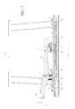
- Fig. 1 an embodiment of the seat bracket according to the invention is shown, according to which a base plate 1 is slidably held in two mutually parallel bottom rails 3.
- the two bottom rails 3 are connected together by means of an intermediate profile.
- the bottom rails may be integrated with intermediate profile in a floor of the passenger compartment or mounted thereon.
- an adapter 16 is mounted, which in turn carries the seat (not shown) of the passenger seat.
- the passenger seat is adjustable via the seat console, inter alia, by the base plate 1 is moved along the floor rails.
- the seat console can be dismantled together with the passenger seat by the base plate 1 is released from the ground rail assembly and lifted.
- a plurality of regularly spaced guide pins 2 are provided on the base plate 1 per bottom rail 3.
- These guide bolts 2 concern on the one hand guide pins which are fixedly connected to the underside of the base plate 1 with this, that is, for example, these may be bolted to the base plate 1 and hold the base plate in the direction parallel to the bottom rails.
- the guide pins concern clamping bolts, which create a clamping contact between bottom rail and base plate.
- an operating lever 4 On the top of the base plate 1, an operating lever 4 is provided, which via a pivot point D (see FIG. 2 ) is pivotable.
- a centering pin 9 is articulated per bottom rail 3 in each case.
- the centering pin 9 can project on the underside of the base plate 1 in each case in locking openings 17 in order to fix the base plate 1 relative to the bottom rail assembly.
- the centering pin 9 is thus slidably held along its longitudinal axis in the vertical direction to the base plate 1 in a socket 10 of the base plate.
- an actuator for actuating a clamping bolt 7 is arranged at the end opposite the pivot point D end of the centering pin 9.
- the clamping bolt 7 is held on the base plate 1 in a guide, which allows an axial displacement of the clamping bolt 7 - which is a special type of guide pin 2.
- the clamping bolt 7 has a mushroom-shaped head, with which the clamping bolt in the bottom rail 3 can be moved frictionally free. Only to set the base plate 1 relative to the bottom rail of the clamping bolt 7 is brought by an axial displacement in a clamping contact between the end head of the clamping bolt 7 and the bottom rail 3.
- the guide pins 2 serve primarily theitKindlertigen fixation of the base plate 1 relative to the floor rail assembly (see in particular Fig. 3 ), ie protection against movement in an angled to the parallels of the bottom rail axis direction.
- a slider 5 With the depression of the operating lever 4, a slider 5 is moved via a lever at the rear end of the operating lever, which slides on the base plate 1.
- the slider 5 has on its upper side a slope which cooperates with a complementary wedge 6.
- the slider 5 is held in a slot and biased by a spring 8, which is mounted on a projecting from the operating lever 4 down extension.
- the wedge 6 is articulated on the clamping bolt 7, so that by moving the slider 5 and the sliding along its upper surface wedge 6 of the clamping bolt 7 is moved up and down, depending on the respective displacement direction of the slider 5.
- the control lever 4 is brought into its lower rest position, inter alia, the slider 5 in the "X" direction (see Fig.
- the operating lever 4 is biased by a spring 12 so as to be pulled or pushed into its lower locking position.
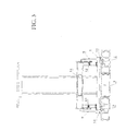
- FIG. 3 It can be seen how the guide pins 2 rest in the C-profile of the bottom rail 3 and protect the base plate 1 against a lateral displacement relative to the bottom rail 3.
- a sliding member 13 is arranged between the bottom rail 3 and the base plate 1, which improves a sliding of the base plate on the bottom rail.
- This sliding element 13 is in the present embodiment, a respective applied to individual guide pin 2 annular disc (see, in particular Fig. 5 ).
- Fig. 4 shows the embodiment of the invention of the seat console in a plan view from above.
- Fig. 5 shows the view from below on the base plate of the Fig. 1 shown seat console.
- a plurality of clamping bolts 7 can be provided, which are not provided centrally, but at the two end portions of the base plate.
Landscapes
- Engineering & Computer Science (AREA)
- Aviation & Aerospace Engineering (AREA)
- Transportation (AREA)
- Mechanical Engineering (AREA)
- Seats For Vehicles (AREA)
Applications Claiming Priority (1)
| Application Number | Priority Date | Filing Date | Title |
|---|---|---|---|
| DE102009057447.6A DE102009057447B4 (de) | 2009-12-09 | 2009-12-09 | Sitzkonsole für einen Fahrgastsitz |
Publications (2)
| Publication Number | Publication Date |
|---|---|
| EP2340963A1 true EP2340963A1 (fr) | 2011-07-06 |
| EP2340963B1 EP2340963B1 (fr) | 2013-09-18 |
Family
ID=43601071
Family Applications (1)
| Application Number | Title | Priority Date | Filing Date |
|---|---|---|---|
| EP10193369.5A Not-in-force EP2340963B1 (fr) | 2009-12-09 | 2010-12-01 | Console d'assise pour un siège passager |
Country Status (2)
| Country | Link |
|---|---|
| EP (1) | EP2340963B1 (fr) |
| DE (1) | DE102009057447B4 (fr) |
Cited By (2)
| Publication number | Priority date | Publication date | Assignee | Title |
|---|---|---|---|---|
| EP3453561A1 (fr) * | 2017-09-06 | 2019-03-13 | Georg Fischer Metallverarbeitung GmbH | Dispositif de raccordement temporaire d'un objet mobile à un rail de retenue |
| CN111169642A (zh) * | 2020-02-25 | 2020-05-19 | 中国民用航空总局第二研究所 | 一种航空座椅地脚锁装置 |
Citations (8)
| Publication number | Priority date | Publication date | Assignee | Title |
|---|---|---|---|---|
| US4114947A (en) | 1977-11-18 | 1978-09-19 | Chas. Olson & Sons | Detachable seat mounting for buses |
| EP0053923A1 (fr) | 1980-12-08 | 1982-06-16 | PTC Aerospace Inc. | Organe d'ancrage de siège |
| DE29712180U1 (de) * | 1997-07-10 | 1997-09-11 | Oettl, Heinrich, 81373 München | Vorrichtung zur schnellösbaren, verschiebbaren und schnell arretierbaren Befestigung eines Fahrzeugausrüstungsteiles, wie z.B. eines Sitzes |
| US5871318A (en) | 1997-11-12 | 1999-02-16 | Be Aerospace, Inc. | Quick-release track fastener |
| DE19851392A1 (de) * | 1997-11-10 | 1999-05-12 | Jungfalk Ancra Gmbh | Vorrichtung zum zeitweiligen Verbinden eines bewegbaren Gegenstandes mit einer Halteschiene |
| EP1790521A1 (fr) | 2005-11-23 | 2007-05-30 | Hermann Schnierle Gesellschaft mit beschränkter Haftung | Support ajustable pour un siège de passager |
| WO2008113610A2 (fr) * | 2007-03-22 | 2008-09-25 | Allsafe Jungfalk Gmbh & Co.Kg | Dispositif servant à fixer des objets |
| EP2253500A2 (fr) * | 2009-05-12 | 2010-11-24 | Georg Fischer Metallverarbeitung GmbH | Dispositif de liaison temporaire d'un objet en mouvement et d'un rail de fixation |
Family Cites Families (3)
| Publication number | Priority date | Publication date | Assignee | Title |
|---|---|---|---|---|
| DE19812490C2 (de) * | 1998-03-21 | 2002-03-14 | Daimler Chrysler Ag | Einrichtung zur lösbaren Befestigung eines Sitzes, insbesondere Fahrzeugsitzes, an einer längsverlaufenden Schiene |
| DE102004022916B3 (de) * | 2004-05-10 | 2005-08-11 | Daimlerchrysler Ag | Vorrichtung zur Verstellung und/oder Befestigung eines Fahrzeugsitzes |
| DE102007014420B4 (de) | 2007-03-22 | 2011-03-31 | Allsafe Jungfalk Gmbh & Co. Kg | Vorrichtung zum Festlegen von Gegenständen |
-
2009
- 2009-12-09 DE DE102009057447.6A patent/DE102009057447B4/de not_active Expired - Fee Related
-
2010
- 2010-12-01 EP EP10193369.5A patent/EP2340963B1/fr not_active Not-in-force
Patent Citations (8)
| Publication number | Priority date | Publication date | Assignee | Title |
|---|---|---|---|---|
| US4114947A (en) | 1977-11-18 | 1978-09-19 | Chas. Olson & Sons | Detachable seat mounting for buses |
| EP0053923A1 (fr) | 1980-12-08 | 1982-06-16 | PTC Aerospace Inc. | Organe d'ancrage de siège |
| DE29712180U1 (de) * | 1997-07-10 | 1997-09-11 | Oettl, Heinrich, 81373 München | Vorrichtung zur schnellösbaren, verschiebbaren und schnell arretierbaren Befestigung eines Fahrzeugausrüstungsteiles, wie z.B. eines Sitzes |
| DE19851392A1 (de) * | 1997-11-10 | 1999-05-12 | Jungfalk Ancra Gmbh | Vorrichtung zum zeitweiligen Verbinden eines bewegbaren Gegenstandes mit einer Halteschiene |
| US5871318A (en) | 1997-11-12 | 1999-02-16 | Be Aerospace, Inc. | Quick-release track fastener |
| EP1790521A1 (fr) | 2005-11-23 | 2007-05-30 | Hermann Schnierle Gesellschaft mit beschränkter Haftung | Support ajustable pour un siège de passager |
| WO2008113610A2 (fr) * | 2007-03-22 | 2008-09-25 | Allsafe Jungfalk Gmbh & Co.Kg | Dispositif servant à fixer des objets |
| EP2253500A2 (fr) * | 2009-05-12 | 2010-11-24 | Georg Fischer Metallverarbeitung GmbH | Dispositif de liaison temporaire d'un objet en mouvement et d'un rail de fixation |
Cited By (2)
| Publication number | Priority date | Publication date | Assignee | Title |
|---|---|---|---|---|
| EP3453561A1 (fr) * | 2017-09-06 | 2019-03-13 | Georg Fischer Metallverarbeitung GmbH | Dispositif de raccordement temporaire d'un objet mobile à un rail de retenue |
| CN111169642A (zh) * | 2020-02-25 | 2020-05-19 | 中国民用航空总局第二研究所 | 一种航空座椅地脚锁装置 |
Also Published As
| Publication number | Publication date |
|---|---|
| EP2340963B1 (fr) | 2013-09-18 |
| DE102009057447A1 (de) | 2011-06-16 |
| DE102009057447B4 (de) | 2018-10-04 |
Similar Documents
| Publication | Publication Date | Title |
|---|---|---|
| EP1470769B1 (fr) | Dispositif de fermeture pour tiroirs | |
| EP3125724B1 (fr) | Guide d'extraction destiné à un tiroir | |
| DE10234892B4 (de) | Bindungseinrichtung für Sportgeräte, insbesondere für ein Snowboard | |
| WO2014180899A1 (fr) | Guidage télescopique | |
| EP1500763B1 (fr) | Dispositif pour empêcher l'ouverture simultanée de tiroirs | |
| DE29712180U1 (de) | Vorrichtung zur schnellösbaren, verschiebbaren und schnell arretierbaren Befestigung eines Fahrzeugausrüstungsteiles, wie z.B. eines Sitzes | |
| DE4333892A1 (de) | Manuell betätigbare mechanische Memory-Vorrichtung | |
| DE69915122T2 (de) | Konstruktion eines öffnungsfähigen fahrzeugdaches | |
| EP1855913B1 (fr) | Dispositif de blocage pour un siege de vehicule reglable | |
| DE102013108540A1 (de) | Fitting zum Festlegen eines Gegenstandes an einer Schiene | |
| DE202011108804U1 (de) | Befestigungsvorrichtung | |
| DE102007021005A1 (de) | Fahrzeugdach mit Deckelelement | |
| EP3380360B1 (fr) | Dispositif de réglage en profondeur d'un siège | |
| EP1606136A2 (fr) | Dispositif pour raccorder un siege de vehicule a un plancher de vehicule | |
| DE102012109751B4 (de) | Auszugführung eines ausziehbaren Möbelteils und Möbel | |
| DE10026530A1 (de) | Vorrichtung zur lösbaren Halterung eines Fahrzeugsitzes an einem Fahrzeugboden | |
| DE102005023007B3 (de) | Einrichtung zum lösbaren Befestigen eines Sitzes | |
| DE10040593C2 (de) | Verriegelungseinrichtung für längsverstellbare Sitze, insbesondere Kraftfahrzeugsitze | |
| EP2340963B1 (fr) | Console d'assise pour un siège passager | |
| DE19812490C2 (de) | Einrichtung zur lösbaren Befestigung eines Sitzes, insbesondere Fahrzeugsitzes, an einer längsverlaufenden Schiene | |
| DE102010052419B4 (de) | Verfahren zur lösbaren Befestigung eines fahrzeugmontierten Verschlusses an einer Fahrzeugkarosserie sowie eine Verschlussanordnung | |
| DE102014104135B4 (de) | Auszugsführung für einen Schubkasten | |
| EP2252510B1 (fr) | Procede de fixation d'un objet sur un rail | |
| DE102010029051A1 (de) | Anschlaganordnung für schwenkbare Karosseriebauteile | |
| DE4041402A1 (de) | Sicherheitsskibindung |
Legal Events
| Date | Code | Title | Description |
|---|---|---|---|
| PUAI | Public reference made under article 153(3) epc to a published international application that has entered the european phase |
Free format text: ORIGINAL CODE: 0009012 |
|
| AK | Designated contracting states |
Kind code of ref document: A1 Designated state(s): AL AT BE BG CH CY CZ DE DK EE ES FI FR GB GR HR HU IE IS IT LI LT LU LV MC MK MT NL NO PL PT RO RS SE SI SK SM TR |
|
| AX | Request for extension of the european patent |
Extension state: BA ME |
|
| 17P | Request for examination filed |
Effective date: 20110927 |
|
| GRAP | Despatch of communication of intention to grant a patent |
Free format text: ORIGINAL CODE: EPIDOSNIGR1 |
|
| INTG | Intention to grant announced |
Effective date: 20130503 |
|
| GRAS | Grant fee paid |
Free format text: ORIGINAL CODE: EPIDOSNIGR3 |
|
| GRAA | (expected) grant |
Free format text: ORIGINAL CODE: 0009210 |
|
| AK | Designated contracting states |
Kind code of ref document: B1 Designated state(s): AL AT BE BG CH CY CZ DE DK EE ES FI FR GB GR HR HU IE IS IT LI LT LU LV MC MK MT NL NO PL PT RO RS SE SI SK SM TR |
|
| REG | Reference to a national code |
Ref country code: GB Ref legal event code: FG4D Free format text: NOT ENGLISH |
|
| REG | Reference to a national code |
Ref country code: CH Ref legal event code: EP |
|
| REG | Reference to a national code |
Ref country code: IE Ref legal event code: FG4D Free format text: LANGUAGE OF EP DOCUMENT: GERMAN |
|
| REG | Reference to a national code |
Ref country code: AT Ref legal event code: REF Ref document number: 632549 Country of ref document: AT Kind code of ref document: T Effective date: 20131015 |
|
| REG | Reference to a national code |
Ref country code: DE Ref legal event code: R096 Ref document number: 502010004768 Country of ref document: DE Effective date: 20131114 |
|
| PG25 | Lapsed in a contracting state [announced via postgrant information from national office to epo] |
Ref country code: NO Free format text: LAPSE BECAUSE OF FAILURE TO SUBMIT A TRANSLATION OF THE DESCRIPTION OR TO PAY THE FEE WITHIN THE PRESCRIBED TIME-LIMIT Effective date: 20131218 Ref country code: HR Free format text: LAPSE BECAUSE OF FAILURE TO SUBMIT A TRANSLATION OF THE DESCRIPTION OR TO PAY THE FEE WITHIN THE PRESCRIBED TIME-LIMIT Effective date: 20130918 Ref country code: CY Free format text: LAPSE BECAUSE OF FAILURE TO SUBMIT A TRANSLATION OF THE DESCRIPTION OR TO PAY THE FEE WITHIN THE PRESCRIBED TIME-LIMIT Effective date: 20130724 Ref country code: LT Free format text: LAPSE BECAUSE OF FAILURE TO SUBMIT A TRANSLATION OF THE DESCRIPTION OR TO PAY THE FEE WITHIN THE PRESCRIBED TIME-LIMIT Effective date: 20130918 Ref country code: SE Free format text: LAPSE BECAUSE OF FAILURE TO SUBMIT A TRANSLATION OF THE DESCRIPTION OR TO PAY THE FEE WITHIN THE PRESCRIBED TIME-LIMIT Effective date: 20130918 |
|
| REG | Reference to a national code |
Ref country code: NL Ref legal event code: VDEP Effective date: 20130918 |
|
| REG | Reference to a national code |
Ref country code: LT Ref legal event code: MG4D |
|
| PG25 | Lapsed in a contracting state [announced via postgrant information from national office to epo] |
Ref country code: RS Free format text: LAPSE BECAUSE OF FAILURE TO SUBMIT A TRANSLATION OF THE DESCRIPTION OR TO PAY THE FEE WITHIN THE PRESCRIBED TIME-LIMIT Effective date: 20130918 Ref country code: SI Free format text: LAPSE BECAUSE OF FAILURE TO SUBMIT A TRANSLATION OF THE DESCRIPTION OR TO PAY THE FEE WITHIN THE PRESCRIBED TIME-LIMIT Effective date: 20130918 Ref country code: LV Free format text: LAPSE BECAUSE OF FAILURE TO SUBMIT A TRANSLATION OF THE DESCRIPTION OR TO PAY THE FEE WITHIN THE PRESCRIBED TIME-LIMIT Effective date: 20130918 Ref country code: FI Free format text: LAPSE BECAUSE OF FAILURE TO SUBMIT A TRANSLATION OF THE DESCRIPTION OR TO PAY THE FEE WITHIN THE PRESCRIBED TIME-LIMIT Effective date: 20130918 Ref country code: GR Free format text: LAPSE BECAUSE OF FAILURE TO SUBMIT A TRANSLATION OF THE DESCRIPTION OR TO PAY THE FEE WITHIN THE PRESCRIBED TIME-LIMIT Effective date: 20131219 |
|
| PG25 | Lapsed in a contracting state [announced via postgrant information from national office to epo] |
Ref country code: CY Free format text: LAPSE BECAUSE OF FAILURE TO SUBMIT A TRANSLATION OF THE DESCRIPTION OR TO PAY THE FEE WITHIN THE PRESCRIBED TIME-LIMIT Effective date: 20130918 |
|
| PG25 | Lapsed in a contracting state [announced via postgrant information from national office to epo] |
Ref country code: CZ Free format text: LAPSE BECAUSE OF FAILURE TO SUBMIT A TRANSLATION OF THE DESCRIPTION OR TO PAY THE FEE WITHIN THE PRESCRIBED TIME-LIMIT Effective date: 20130918 Ref country code: SK Free format text: LAPSE BECAUSE OF FAILURE TO SUBMIT A TRANSLATION OF THE DESCRIPTION OR TO PAY THE FEE WITHIN THE PRESCRIBED TIME-LIMIT Effective date: 20130918 Ref country code: EE Free format text: LAPSE BECAUSE OF FAILURE TO SUBMIT A TRANSLATION OF THE DESCRIPTION OR TO PAY THE FEE WITHIN THE PRESCRIBED TIME-LIMIT Effective date: 20130918 Ref country code: IS Free format text: LAPSE BECAUSE OF FAILURE TO SUBMIT A TRANSLATION OF THE DESCRIPTION OR TO PAY THE FEE WITHIN THE PRESCRIBED TIME-LIMIT Effective date: 20140118 Ref country code: NL Free format text: LAPSE BECAUSE OF FAILURE TO SUBMIT A TRANSLATION OF THE DESCRIPTION OR TO PAY THE FEE WITHIN THE PRESCRIBED TIME-LIMIT Effective date: 20130918 |
|
| PG25 | Lapsed in a contracting state [announced via postgrant information from national office to epo] |
Ref country code: PL Free format text: LAPSE BECAUSE OF FAILURE TO SUBMIT A TRANSLATION OF THE DESCRIPTION OR TO PAY THE FEE WITHIN THE PRESCRIBED TIME-LIMIT Effective date: 20130918 Ref country code: ES Free format text: LAPSE BECAUSE OF FAILURE TO SUBMIT A TRANSLATION OF THE DESCRIPTION OR TO PAY THE FEE WITHIN THE PRESCRIBED TIME-LIMIT Effective date: 20130918 |
|
| REG | Reference to a national code |
Ref country code: DE Ref legal event code: R097 Ref document number: 502010004768 Country of ref document: DE |
|
| BERE | Be: lapsed |
Owner name: SORTIMO SPEEDWAVE G.M.B.H. Effective date: 20131231 |
|
| PG25 | Lapsed in a contracting state [announced via postgrant information from national office to epo] |
Ref country code: PT Free format text: LAPSE BECAUSE OF FAILURE TO SUBMIT A TRANSLATION OF THE DESCRIPTION OR TO PAY THE FEE WITHIN THE PRESCRIBED TIME-LIMIT Effective date: 20140120 |
|
| PLBE | No opposition filed within time limit |
Free format text: ORIGINAL CODE: 0009261 |
|
| STAA | Information on the status of an ep patent application or granted ep patent |
Free format text: STATUS: NO OPPOSITION FILED WITHIN TIME LIMIT |
|
| 26N | No opposition filed |
Effective date: 20140619 |
|
| PG25 | Lapsed in a contracting state [announced via postgrant information from national office to epo] |
Ref country code: MC Free format text: LAPSE BECAUSE OF FAILURE TO SUBMIT A TRANSLATION OF THE DESCRIPTION OR TO PAY THE FEE WITHIN THE PRESCRIBED TIME-LIMIT Effective date: 20130918 Ref country code: LU Free format text: LAPSE BECAUSE OF FAILURE TO SUBMIT A TRANSLATION OF THE DESCRIPTION OR TO PAY THE FEE WITHIN THE PRESCRIBED TIME-LIMIT Effective date: 20131201 Ref country code: IT Free format text: LAPSE BECAUSE OF FAILURE TO SUBMIT A TRANSLATION OF THE DESCRIPTION OR TO PAY THE FEE WITHIN THE PRESCRIBED TIME-LIMIT Effective date: 20130918 |
|
| REG | Reference to a national code |
Ref country code: IE Ref legal event code: MM4A |
|
| PG25 | Lapsed in a contracting state [announced via postgrant information from national office to epo] |
Ref country code: DK Free format text: LAPSE BECAUSE OF FAILURE TO SUBMIT A TRANSLATION OF THE DESCRIPTION OR TO PAY THE FEE WITHIN THE PRESCRIBED TIME-LIMIT Effective date: 20130918 |
|
| REG | Reference to a national code |
Ref country code: DE Ref legal event code: R097 Ref document number: 502010004768 Country of ref document: DE Effective date: 20140619 |
|
| PG25 | Lapsed in a contracting state [announced via postgrant information from national office to epo] |
Ref country code: BE Free format text: LAPSE BECAUSE OF NON-PAYMENT OF DUE FEES Effective date: 20131231 Ref country code: IE Free format text: LAPSE BECAUSE OF NON-PAYMENT OF DUE FEES Effective date: 20131201 |
|
| PG25 | Lapsed in a contracting state [announced via postgrant information from national office to epo] |
Ref country code: RO Free format text: LAPSE BECAUSE OF FAILURE TO SUBMIT A TRANSLATION OF THE DESCRIPTION OR TO PAY THE FEE WITHIN THE PRESCRIBED TIME-LIMIT Effective date: 20130918 |
|
| PG25 | Lapsed in a contracting state [announced via postgrant information from national office to epo] |
Ref country code: SM Free format text: LAPSE BECAUSE OF FAILURE TO SUBMIT A TRANSLATION OF THE DESCRIPTION OR TO PAY THE FEE WITHIN THE PRESCRIBED TIME-LIMIT Effective date: 20130918 |
|
| PG25 | Lapsed in a contracting state [announced via postgrant information from national office to epo] |
Ref country code: TR Free format text: LAPSE BECAUSE OF FAILURE TO SUBMIT A TRANSLATION OF THE DESCRIPTION OR TO PAY THE FEE WITHIN THE PRESCRIBED TIME-LIMIT Effective date: 20130918 |
|
| PG25 | Lapsed in a contracting state [announced via postgrant information from national office to epo] |
Ref country code: HU Free format text: LAPSE BECAUSE OF FAILURE TO SUBMIT A TRANSLATION OF THE DESCRIPTION OR TO PAY THE FEE WITHIN THE PRESCRIBED TIME-LIMIT; INVALID AB INITIO Effective date: 20101201 Ref country code: BG Free format text: LAPSE BECAUSE OF FAILURE TO SUBMIT A TRANSLATION OF THE DESCRIPTION OR TO PAY THE FEE WITHIN THE PRESCRIBED TIME-LIMIT Effective date: 20130918 Ref country code: MK Free format text: LAPSE BECAUSE OF FAILURE TO SUBMIT A TRANSLATION OF THE DESCRIPTION OR TO PAY THE FEE WITHIN THE PRESCRIBED TIME-LIMIT Effective date: 20130918 |
|
| REG | Reference to a national code |
Ref country code: CH Ref legal event code: PL |
|
| PG25 | Lapsed in a contracting state [announced via postgrant information from national office to epo] |
Ref country code: MT Free format text: LAPSE BECAUSE OF FAILURE TO SUBMIT A TRANSLATION OF THE DESCRIPTION OR TO PAY THE FEE WITHIN THE PRESCRIBED TIME-LIMIT Effective date: 20130918 |
|
| PG25 | Lapsed in a contracting state [announced via postgrant information from national office to epo] |
Ref country code: CH Free format text: LAPSE BECAUSE OF NON-PAYMENT OF DUE FEES Effective date: 20141231 Ref country code: LI Free format text: LAPSE BECAUSE OF NON-PAYMENT OF DUE FEES Effective date: 20141231 |
|
| REG | Reference to a national code |
Ref country code: FR Ref legal event code: PLFP Year of fee payment: 6 |
|
| REG | Reference to a national code |
Ref country code: FR Ref legal event code: PLFP Year of fee payment: 7 |
|
| REG | Reference to a national code |
Ref country code: FR Ref legal event code: PLFP Year of fee payment: 8 |
|
| PG25 | Lapsed in a contracting state [announced via postgrant information from national office to epo] |
Ref country code: AL Free format text: LAPSE BECAUSE OF FAILURE TO SUBMIT A TRANSLATION OF THE DESCRIPTION OR TO PAY THE FEE WITHIN THE PRESCRIBED TIME-LIMIT Effective date: 20130918 |
|
| PGFP | Annual fee paid to national office [announced via postgrant information from national office to epo] |
Ref country code: AT Payment date: 20181213 Year of fee payment: 9 |
|
| PGFP | Annual fee paid to national office [announced via postgrant information from national office to epo] |
Ref country code: GB Payment date: 20181219 Year of fee payment: 9 Ref country code: FR Payment date: 20181218 Year of fee payment: 9 |
|
| PGFP | Annual fee paid to national office [announced via postgrant information from national office to epo] |
Ref country code: DE Payment date: 20190214 Year of fee payment: 9 |
|
| REG | Reference to a national code |
Ref country code: DE Ref legal event code: R119 Ref document number: 502010004768 Country of ref document: DE |
|
| REG | Reference to a national code |
Ref country code: AT Ref legal event code: MM01 Ref document number: 632549 Country of ref document: AT Kind code of ref document: T Effective date: 20191201 |
|
| GBPC | Gb: european patent ceased through non-payment of renewal fee |
Effective date: 20191201 |
|
| PG25 | Lapsed in a contracting state [announced via postgrant information from national office to epo] |
Ref country code: DE Free format text: LAPSE BECAUSE OF NON-PAYMENT OF DUE FEES Effective date: 20200701 Ref country code: GB Free format text: LAPSE BECAUSE OF NON-PAYMENT OF DUE FEES Effective date: 20191201 Ref country code: FR Free format text: LAPSE BECAUSE OF NON-PAYMENT OF DUE FEES Effective date: 20191231 |
|
| PG25 | Lapsed in a contracting state [announced via postgrant information from national office to epo] |
Ref country code: AT Free format text: LAPSE BECAUSE OF NON-PAYMENT OF DUE FEES Effective date: 20191201 |