EP2345612A2 - Abziehvorrichtung - Google Patents
Abziehvorrichtung Download PDFInfo
- Publication number
- EP2345612A2 EP2345612A2 EP11150362A EP11150362A EP2345612A2 EP 2345612 A2 EP2345612 A2 EP 2345612A2 EP 11150362 A EP11150362 A EP 11150362A EP 11150362 A EP11150362 A EP 11150362A EP 2345612 A2 EP2345612 A2 EP 2345612A2
- Authority
- EP
- European Patent Office
- Prior art keywords
- unit
- winding
- tube
- cradle
- yarn
- Prior art date
- Legal status (The legal status is an assumption and is not a legal conclusion. Google has not performed a legal analysis and makes no representation as to the accuracy of the status listed.)
- Withdrawn
Links
- 238000004804 winding Methods 0.000 claims abstract description 242
- 230000009471 action Effects 0.000 claims description 4
- 239000012530 fluid Substances 0.000 abstract description 20
- 238000005304 joining Methods 0.000 abstract description 6
- 239000004753 textile Substances 0.000 abstract description 3
- 238000009987 spinning Methods 0.000 description 58
- 230000007246 mechanism Effects 0.000 description 34
- 230000008878 coupling Effects 0.000 description 32
- 238000010168 coupling process Methods 0.000 description 32
- 238000005859 coupling reaction Methods 0.000 description 32
- 238000007599 discharging Methods 0.000 description 9
- 238000000034 method Methods 0.000 description 7
- 238000010586 diagram Methods 0.000 description 6
- 230000008569 process Effects 0.000 description 6
- 230000004044 response Effects 0.000 description 6
- 230000008859 change Effects 0.000 description 5
- 239000000835 fiber Substances 0.000 description 5
- 230000007547 defect Effects 0.000 description 4
- 238000011144 upstream manufacturing Methods 0.000 description 4
- 238000004891 communication Methods 0.000 description 3
- 239000002699 waste material Substances 0.000 description 3
- 238000013459 approach Methods 0.000 description 2
- 230000004048 modification Effects 0.000 description 2
- 238000012986 modification Methods 0.000 description 2
- 238000012544 monitoring process Methods 0.000 description 2
- 230000003287 optical effect Effects 0.000 description 2
- 238000003825 pressing Methods 0.000 description 2
- 230000009467 reduction Effects 0.000 description 2
- WURBVZBTWMNKQT-UHFFFAOYSA-N 1-(4-chlorophenoxy)-3,3-dimethyl-1-(1,2,4-triazol-1-yl)butan-2-one Chemical compound C1=NC=NN1C(C(=O)C(C)(C)C)OC1=CC=C(Cl)C=C1 WURBVZBTWMNKQT-UHFFFAOYSA-N 0.000 description 1
- 238000010042 air jet spinning Methods 0.000 description 1
- 230000001174 ascending effect Effects 0.000 description 1
- 230000008901 benefit Effects 0.000 description 1
- 230000015556 catabolic process Effects 0.000 description 1
- 235000013351 cheese Nutrition 0.000 description 1
- 238000004140 cleaning Methods 0.000 description 1
- 238000006731 degradation reaction Methods 0.000 description 1
- 230000007704 transition Effects 0.000 description 1
Images








Classifications
-
- D—TEXTILES; PAPER
- D01—NATURAL OR MAN-MADE THREADS OR FIBRES; SPINNING
- D01H—SPINNING OR TWISTING
- D01H13/00—Other common constructional features, details or accessories
- D01H13/005—Service carriages travelling along the machines
-
- B—PERFORMING OPERATIONS; TRANSPORTING
- B65—CONVEYING; PACKING; STORING; HANDLING THIN OR FILAMENTARY MATERIAL
- B65H—HANDLING THIN OR FILAMENTARY MATERIAL, e.g. SHEETS, WEBS, CABLES
- B65H54/00—Winding, coiling, or depositing filamentary material
- B65H54/02—Winding and traversing material on to reels, bobbins, tubes, or like package cores or formers
- B65H54/22—Automatic winding machines, i.e. machines with servicing units for automatically performing end-finding, interconnecting of successive lengths of material, controlling and fault-detecting of the running material and replacing or removing of full or empty cores
- B65H54/26—Automatic winding machines, i.e. machines with servicing units for automatically performing end-finding, interconnecting of successive lengths of material, controlling and fault-detecting of the running material and replacing or removing of full or empty cores having one or more servicing units moving along a plurality of fixed winding units
-
- B—PERFORMING OPERATIONS; TRANSPORTING
- B65—CONVEYING; PACKING; STORING; HANDLING THIN OR FILAMENTARY MATERIAL
- B65H—HANDLING THIN OR FILAMENTARY MATERIAL, e.g. SHEETS, WEBS, CABLES
- B65H67/00—Replacing or removing cores, receptacles, or completed packages at paying-out, winding, or depositing stations
- B65H67/04—Arrangements for removing completed take-up packages and or replacing by cores, formers, or empty receptacles at winding or depositing stations; Transferring material between adjacent full and empty take-up elements
-
- D—TEXTILES; PAPER
- D01—NATURAL OR MAN-MADE THREADS OR FIBRES; SPINNING
- D01H—SPINNING OR TWISTING
- D01H9/00—Arrangements for replacing or removing bobbins, cores, receptacles, or completed packages at paying-out or take-up stations ; Combination of spinning-winding machine
- D01H9/02—Arrangements for replacing or removing bobbins, cores, receptacles, or completed packages at paying-out or take-up stations ; Combination of spinning-winding machine for removing completed take-up packages and replacing by bobbins, cores, or receptacles at take-up stations; Transferring material between adjacent full and empty take-up elements
- D01H9/08—Doffing arrangements independent of spinning or twisting machines
- D01H9/10—Doffing carriages ; Loading carriages with cores
-
- B—PERFORMING OPERATIONS; TRANSPORTING
- B65—CONVEYING; PACKING; STORING; HANDLING THIN OR FILAMENTARY MATERIAL
- B65H—HANDLING THIN OR FILAMENTARY MATERIAL, e.g. SHEETS, WEBS, CABLES
- B65H2701/00—Handled material; Storage means
- B65H2701/30—Handled filamentary material
- B65H2701/31—Textiles threads or artificial strands of filaments
Definitions
- the present invention relates to a doffing apparatus.
- Textile machines such as spinning machines and automatic winders, that include a winding apparatus that forms a package by winding a yarn onto a winding tube held by a cradle, and a doffing apparatus that discharges a fully-wound package are known in the art.
- the doffing apparatus of such a textile machine discharges the fully-wound package by opening the cradle. Subsequently, an empty winding tube is supplied to the cradle, the empty winding tube is mounted on the cradle, the cradle is closed, and a yarn is attached to the empty winding tube that was mounted on the cradle.
- discharging of the fully-wound package, supplying of the winding tube, and mounting of the winding tube and attaching of the yarn to the winding tube are performed as a single sequence of operations (for example, see Japanese published unexamined applications 2008-162712 and 2005-219880 ).
- the present invention has been made to address the above-explained problems. It is an object of the present invention is to present a configuration that can perform only situation-sensitive required operations, skip unnecessary operations, and perform only least required operations. This configuration presents a doffing apparatus capable of efficiently performing a doffing operation.
- a doffing apparatus performs a doffing operation with respect to a winding apparatus.
- the winding apparatus includes a yarn feeding unit that feeds a yarn and a winding-tube holding unit that holds a winding tube and forms a package by winding the yarn fed from the yarn feeding unit onto the winding tube held by the winding-tube holding unit.
- the doffing apparatus includes an operating unit that operates the winding-tube holding unit such that the winding tube can be attached or detached; a winding-tube supplying unit that supplies the winding tube to the winding-tube holding unit; a yarn guiding unit that catches the yarn fed from the yarn feeding unit and guides the yarn to the winding tube; an operating-unit driving source that drives the operating unit; and a preparatory-unit driving source that is separate from the operating-unit driving source and that drives the winding-tube supplying unit and the yarn guiding unit.
- FIG. 1 is a schematic front view of the automatic winder according to the first embodiment of the present invention.
- FIG. 2 is a schematic side view of one winding unit and the doffing apparatus of the automatic winder.
- the automatic winder 1 includes a plurality of winding units 2 (winding apparatuses) arranged in a row and a doffing apparatus 3 capable of traveling in a direction (left-right direction in FIG. 1 ), along which the winding units 2 are arranged.
- the winding unit 2 winds on a winding tube 7 spun yarns Y unwound from a plurality of yarn supplying bobbins 5 while performing yarn joining to form a fully-wound package 6 of a specific yarn amount.
- the winding unit 2 includes, at its bottom end, a tray 11 and, at its top end, a cradle 12 (winding-tube holding unit).
- the spun yarns Y unwound from the yarn supplying bobbins 5 supported on the tray 11 are wound on the winding tube 7 rotatably supported by the cradle 12 and driven to rotate by rotation of a traversing drum 13.
- the winding unit 2 includes a splicer device 20, a yarn-defect removal apparatus 19 that detects a yarn defect, such as a slub, and the traversing drum 13 that rotates the winding tube 7 held by the cradle 12 that are arranged in this order from a lower side to an upper side (i.e., from upstream to downstream along a yarn feed direction) along a yarn path from the yarn supplying bobbins 5 supported on the tray 11 to the winding tube 7 held by the cradle 12.
- a yarn-defect removal apparatus 19 that detects a yarn defect, such as a slub
- the traversing drum 13 that rotates the winding tube 7 held by the cradle 12 that are arranged in this order from a lower side to an upper side (i.e., from upstream to downstream along a yarn feed direction) along a yarn path from the yarn supplying bobbins 5 supported on the tray 11 to the winding tube 7 held by the cradle 12.
- the winding unit 2 further includes, although not shown, a bobbin changer that conveys out an empty yarn supplying bobbin 5, from which all the spun yarn Y has been unwound, from the tray 11 and places a new yarn supplying bobbin 5, on which a spun yarn Y is wound, on the tray 11.
- a cutter is arranged between the yarn-defect removal apparatus 19 and the splicer device 20 to cut the spun yarn Y extending from the yarn supplying bobbin 5 to the package 6 when the yarn-defect removal apparatus 19 detects a yarn defect or when doffing of the package 6 is to be performed.
- a yarn-guiding suction device that sucks the spun yarn Y cut by the cutter and guides the spun yarn Y to the splicer device 20.
- Yarn joining performed by using the splicer device 20 or the like is a known technique disclosed in, for instance, Japanese published unexamined application 2009-84023 ; therefore, an explanation of the yarn joining is omitted herefrom.
- the traversing drum 13 is driven by a driving motor 47 (see FIG. 6 ) to rotate in a predetermined winding direction.
- a traverse groove is formed on the surface of the traversing drum 13.
- the spun yarn Y is wound on the winding tube 7 while traversing along the traverse groove. Meanwhile, it is allowable to use a simple driving drum without a groove instead of the traversing drum 13, and use a separate traversing device to perform traversing of the spun yarn Y.
- the cradle 12 includes two cradle arms, or, more specifically, cradle arms 12a and 12b that rotatably hold the winding tube 7 in a manner to sandwich the winding tube 7 therebetween and a cradle lever 12c arranged substantially parallel with the cradle arm 12a and coupled to a longitudinal center of the top surface of the cradle arm 12a such that the cradle lever 12c is pivotable about a rotary shaft 14.
- the cradle arm 12a includes a protruding portion 12ding in an axial direction of the winding tube 7 being held and a sliding portion 12e slidable relative to the protruding portion 12d.
- the sliding portion 12e is inserted into the winding tube 7 to rotatably hold the winding tube 7 between the sliding portion 12e and the cradle arm 12b.
- the sliding portion 12e is urged in a direction (direction toward the winding tube 7 being held) away from the protruding portion 12d.
- the cradle lever 12c is coupled to a fixture 15 fixed onto the sliding portion 12e and moves integrally with the sliding portion 12e.
- opening direction a horizontal force in a direction (hereinafter, referred to as "opening direction") away from the winding tube 7 is applied from the doffing apparatus 3, which will be described later, onto the cradle lever 12c, the cradle lever 12c pivots about the rotary shaft 14 in the opening direction.
- the sliding portion 12e is slid, together with the fixture 15, toward the protruding portion 12d. This causes the sliding portion 12e to move out of the winding tube 7, placing the cradle 12 in an open state and allowing the winding tube 7 to be removed from the cradle 12.
- the urging force in a direction (hereinafter, referred to as "closing direction" opposite to the opening direction) away from the protruding portion 12d of the sliding portion 12e causes the cradle lever 12c to pivot in the closing direction.
- the pivoting motion of the cradle lever 12c opens and closes the cradle 12, allowing the winding tube 7 to be mounted on and removed from the cradle 12.
- the cradle 12 is pivotable about a rotary shaft 16 to be raised and lowered.
- the cradle lever 12c pulls the cradle lever 12c up, the cradle 12 pivots about the rotary shaft 16 to be raised to a package-removing position of the package 6.
- the cradle lever 12c pushes the cradle lever 12c down, the cradle 12 is lowered to a winding position where the winding tube 7 held by the cradle 12 contacts the traversing drum 13.
- the doffing apparatus 3 pulls the cradle 12 up to put the cradle 12 in the package-removing position.
- the doffing apparatus 3 takes out the package 6 held by the cradle 12 from the traversing drum 13 and then puts the cradle 12 in the open state and removes the package 6 from the cradle 12, thereby discharging the package 6.
- the discharged package 6 is delivered through a package guide 28 to a conveying device 61.
- a winding-tube stocker 4 storing a plurality of empty winding tubes 7, on each of which the spun yarn Y is not wound, is provided above the cradle 12.
- the doffing apparatus 3 lowers the cradle 12 to the winding position while maintaining the open state of the cradle 12.
- a chuck 33, which will be described later, of the doffing apparatus 3 delivers the winding tube 7 fed from the winding-tube stocker 4 in between the two cradle arms, or, more specifically, the cradle arms 12a and 12b.
- the doffing apparatus 3 places the cradle 12 in the closed state to hold the winding tube 7 in a sandwiching manner, thereby mounting the winding tube 7 on the cradle 12.
- the doffing apparatus 3 is described below. As illustrated in FIG. 2 , the doffing apparatus 3 is arranged on a frame 30 of the automatic winder 1 and travels above the winding units 2 on a rail 31 extending in the direction, along which the winding units 2 are arranged in the row. When the package 6 of one of the winding units 2 is fully wound, the doffing apparatus 3 stops at a predetermined position to perform a doffing operation.
- the doffing apparatus 3 includes a cradle opener 32 that operates the cradle 12, the chuck 33 that catches one of the winding tubes 7 in the winding-tube stocker 4 and conveys the caught winding tube 7 to a position where the cradle 12 can hold the winding tube 7 in the sandwiching manner, and a sensor 51 that determines whether the cradle 12 is holding the package 6.
- the cradle opener 32 (operating unit) includes a lever driving mechanism 34 and an open lever 37.
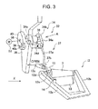
- the lever driving mechanism 34 includes a swing unit 34a coupled to a basal end of a first lever 37a, which will be described later, of the open lever 37, a support 34c fixed to a rotary shaft 36 protruding in an axial direction of the traversing drum 13 from a frame 35, rotatable relative to the frame 35, and supporting the swing unit 34a in a manner allowing the swing unit 34a to pivot about a rotary shaft 34b, a driving motor 52 that rotates the rotary shaft 36, and a fluid pressure cylinder 38 that drives the swing unit 34a to cause the swing unit 34a to pivot relative to the support 34c.
- the swing unit 34a is urged to pivot about the rotary shaft 34b toward the support 34c by a torsion spring 34d.
- the swing unit 34a is pivotable about the rotary shaft 34b in response to retraction and advancement of a rod 38a protruding from the fluid pressure cylinder 38 fixed to the support 34c.
- the swing unit 34a is movable between a closed position where the rod 38a has retracted and an open position where the rod 38a has advanced.
- the open lever 37 includes the first lever 37a fixed to the swing unit 34a and extending in a radial direction of the rotary shaft 36 and a second lever 37b protruding upward from a near-distal-end portion of the first lever 37a and bent in a direction (leftward in FIG. 3 ) away from the winding tube 7 held by the cradle 12.
- the open lever 37 is rotatable integrally with the rotary shaft 36 because the support 34c of the cradle opener 32 is fixed to the rotary shaft 36.
- the rotary shaft 36 is coupled to a stopper 39.
- the stopper 39 is movable along a slit 40a defined, along the circumference of the rotary shaft 36, in a disk 40 mounted on the frame 35. This allows the open lever 37 to rotate only in a movable range corresponding to a range where the stopper 39 is movable along the slit 40a.
- the open lever 37 pivots about the rotary shaft 36, raising the distal end of the open lever 37. This brings the distal end of the first lever 37a into contact with a portion of a bottom surface of the cradle lever 12c, causing the distal end of the first lever 37a to push up the cradle lever 12c.
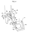
- the open lever 37 pivots to the open position with the distal end of the open lever 37 ascending to an upper-edge position, as illustrated in FIG. 4 , the cradle 12 is placed in the open state and at the package-removing position. In this state, the package 6 can be discharged from the cradle 12.
- the open lever 37 pivots from the closed position to the open position by causing the rod 38a of the fluid pressure cylinder 38 to advance.
- the cradle 12 is caused to transition from the closed state to the open state while moving from the winding position to the package-removing position because the rotary shaft 36 is rotated by the driving motor 52 counterclockwise as viewed along the X direction.
- the open lever 37 is stopped at the lower-edge position when the second lever 37b comes into contact with the top surface of the cradle lever 12c of the cradle 12 placed at the winding position. In this state, a minute clearance is left between the stopper 39 and one end of the slit 40a. Hence, the open lever 37 can be further lowered only by a small distance.
- the open lever 37 is stopped at the upper-edge position when the first lever 37a comes into contact with the bottom surface of the cradle 12 placed at the package-removing position. Accordingly, a minute clearance is left between the stopper 39 and the other end of the slit 40a. Hence, the open lever 37 can be further raised only by a small distance.
- the sensor 51 is an optical sensor including a light-emitting unit and a light-receiving unit. Light emitted from the light-emitting unit is reflected from the package 6 held by the cradle 12 and the reflected light is received by the light-receiving unit. When the light emitted from the light-emitting unit is received by the light-receiving unit, the sensor 51 determines that the cradle 12 is holding the package 6; whereas when the light emitted from the light-emitting unit is not received by the light-receiving unit, the sensor 51 determines that the cradle 12 is not holding the package 6. The result of this determination is transmitted to a doffing controller 42, which will be described later, of the doffing apparatus 3.
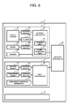
- FIG. 6 is a control block diagram of the automatic winder 1. As illustrated in FIG. 6 , as the configuration related to control operations of the automatic winder 1, each of the winding units 2 includes a unit controller 41.
- the doffing apparatus 3 includes the doffing controller 42 (controlling unit).
- the plurality of unit controllers 41 and the doffing controller 42 are connected to the machine controller 43 through a communication network.
- the configuration mentioned above allows a doffing signal to be transmitted from the unit controller 41 to the doffing controller 42 via the machine controller 43.
- the machine controller 43 is provided at an end portion of the automatic winder 1 to perform centralized control of the automatic winder 1 and is capable of transmitting various setting values, e.g., a signal indicative of the shape of the winding tube 7 held by the cradle 12, to the unit controller 41 and the doffing controller 42.
- a driving motor 46 that drives the splicer device 20, a driving motor 47 that rotates the traversing drum 13, and the yarn-defect removal apparatus 19 are connected to the unit controller 41 of the winding unit 2.
- the fluid pressure cylinder 38 (first driving source) that causes the cradle opener 32 to perform opening/closing operation to open and close the cradle 12, the driving motor 52 (second driving source) that causes the cradle opener 32 to perform raising/lowering operation to raise and lower the cradle 12, a driving motor 54 that rotates a wheel 53 that causes the doffing apparatus 3 to slide in the direction, along which the winding units 2 are arranged in the row, and the sensor 51 are connected to the doffing controller 42 of the doffing apparatus 3.
- the doffing controller 42 further includes a storing unit 55 that stores therein a movement amount, which depends on the shape of the winding tube 7, of the cradle 12 and a signal receiving unit 56 that receives signals from the machine controller 43.
- the doffing operation is described below.
- the cradle 12 When winding of spun yarn Y unwound from the yarn supplying bobbin 5 is to be performed, the cradle 12 is placed at the winding position. The cradle 12 winds the spun yarn Y on the package 6 by bringing the package 6 held by the cradle 12 into contact with the traversing drum 13 to cause the package 6 to be rotated by rotation of the traversing drum 13.
- the package 6 is determined to be fully wound.
- a doffing signal is transmitted from the unit controller 41 of the winding unit 2 to the doffing controller 42 of the doffing apparatus 3 via the machine controller 43.
- the winding unit 2 actuates the cutter to have the spun yarn Y cut.
- an upper yarn connected with the spun yarn Y wound on the package 6 is taken up by the package 6 held by the cradle 12; a lower yarn (hereinafter, "yarn on the yarn supplying bobbin 5 side") connected to the spun yarn Y of the yarn supplying bobbin 5 is sucked and caught.
- the doffing controller 42 of the doffing apparatus 3 receives the doffing signal. In response thereto, the doffing apparatus 3 travels on the rail 31 and stops at a position above the package 6 of the winding unit 2 having the fully-wound package 6.
- the doffing controller 42 of the doffing apparatus 3 causes a yarn catching unit 60 (yarn guiding unit) to catch the yarn on the yarn supplying bobbin 5 side. Substantially simultaneously, the doffing controller 42 causes the rod 38a of the fluid pressure cylinder 38 to retract and drives the driving motor 52 with the open lever 37 placed at the closed position, thereby rotating the cradle opener 32. This operation moves the open lever 37 to the lower-edge position where the second lever 37b contacts the cradle lever 12c.
- the doffing controller 42 causes the rod 38a of the fluid pressure cylinder 38 to advance so that the open lever 37 pivots from the closed position toward the open position by a degree that will not allow removal of the package 6 from the cradle 12. Subsequently, the doffing controller 42 drives the driving motor 52 to rotate the cradle opener 32, thereby causing the open lever 37 to move to the upper-edge position. This causes the first lever 37a of the open lever 37 to ascend while pushing up the cradle lever 12c and also causes the package 6 held by the cradle 12 to ascend away from the traversing drum 13. The doffing controller 42 causes the open lever 37 to ascend, while simultaneously pivoting to the open position, to the upper-edge position.
- the cradle 12 is opened while being raised.
- the open lever 37 has reached the upper-edge position
- the cradle 12 is placed in the open state and at the package-removing position, at which the package 6 is removed from the cradle 12.
- the package guide 28 that causes the package 6 to roll to guide the package 6 to the conveying device 61 is inclined to the cradle 12.
- the package 6 removed from the cradle 12 rolls on the package guide 28 inclined by the angle in relation to ascent of the cradle 12 to be discharged onto the conveying device 61.
- the package 6 is removed from the cradle 12 in this manner.
- the doffing controller 42 of the doffing apparatus 3 puts the open lever 37 at the open position.
- the doffing controller 42 drives the driving motor 52 to rotate the cradle opener 32 with the cradle 12 maintained in the open state, thereby moving the open lever 37 to the lower-edge position.
- This operation causes the second lever 37b of the open lever 37 to press down the cradle lever 12c, which in turn lowers the cradle 12 to the winding position.
- the doffing controller 42 causes the chuck 33 to catch the winding tube 7 supplied from the winding-tube stocker 4 and convey the caught winding tube 7 to a position above the traversing drum 13.
- the chuck 33 sets the winding tube 7 in between the two cradle arms, or, more specifically, the cradle arms 12a and 12b.
- the doffing controller 42 of the doffing apparatus 3 operates the yarn catching unit 60 to hook the yarn on the yarn supplying bobbin 5 side on a yarn handling lever (not shown).
- the yarn handling lever causes the yarn on the yarn supplying bobbin 5 side to traverse between the open cradle 12 and the winding tube 7.
- the doffing controller 42 causes the rod 38a of the fluid pressure cylinder 38 to retract to place the open lever 37 at the closed position and the cradle 12 in the closed state.
- the winding tube 7 is mounted on the cradle 12 with the yarn on the yarn supplying bobbin 5 side interposed between the winding tube 7 and one end of the cradle arm 12a. This operation is performed while the winding tube 7 in contact with the traversing drum 13.
- the doffing controller 42 of the doffing apparatus 3 transmits a signal to the winding unit 2 so that the unit controller 41 drives the driving motor 46 to rotate the traversing drum 13 at a low revolution speed, thereby forming a bunch winding on an end of the winding tube 7. Subsequently, the doffing controller 42 causes the traversing drum 13 to rotate at a high revolution speed to resume winding of the spun yarn Y unwound from the yarn supplying bobbin 5 on the winding tube 7.
- the doffing operation is performed as discussed above by performing a sequence of operations including removal of the package 6, supplying and mounting of the winding tube 7, and a preparatory operation, including threading, for resumption of winding.
- the yarn catching unit 60 and the yarn handling lever which form a mechanism for forming a bunch winding, are driven by a driving source 62 (preparatory-unit driving source) differing from the fluid pressure cylinder 38 and the driving motor 52 that open/close and raise/lower the cradle opener 32.
- the storing unit 55 of the doffing controller 42 stores therein program codes for performing the doffing operation.
- the doffing controller 42 reads the program codes stored in the storing unit 55 to drive the fluid pressure cylinder 38, the driving motor 52, and the driving source 62.
- the doffing controller 42 selectively performs operations in a first mode to perform the removal of the package 6 and the supplying and mounting of the winding tube 7 and operations in a second mode to perform only the removal of the package 6 by driving the fluid pressure cylinder 38 and the driving motor 52.
- a doffing signal is transmitted from the unit controller 41 of the winding unit 2 to the doffing controller 42 of the doffing apparatus 3 via the machine controller 43.
- the doffing controller 42 Upon receiving the doffing signal in a situation where it is determined that the cradle 12 is holding the package 6, the doffing controller 42 causes the fluid pressure cylinder 38 and the driving motor 52 to perform the sequence of operations in the first mode mentioned above as the doffing operation.
- the doffing controller 42 receives a signal indicating that the cradle 12 is not holding the package 6. Upon receiving the signal, the doffing controller 42 drives the fluid pressure cylinder 38 to perform the operations in the first mode.
- the doffing controller 42 does not cause all the operations to be performed but causes the cradle opener 32 to perform only the opening/closing operation to open and close the cradle 12 by driving the fluid pressure cylinder 38 so that the discharging of the package 6 involving the raising/lowering operation of the cradle 12 is skipped and only the supplying and mounting of the winding tube 7 and the resumption of winding including threading are performed.
- a lot-change signal can be transmitted from the unit controller 41 of the winding unit 2 to the doffing controller 42 of the doffing apparatus 3 via the machine controller 43.
- the doffing controller 42 Upon receiving the lot-change signal, after the winding tube 7 being currently wound has been fully wound, the doffing controller 42 is not scheduled to perform another winding for a current lot. Accordingly, the doffing controller 42 causes the fluid pressure cylinder 38 and the driving motor 52 to perform the operations in the second mode so that winding on all the winding units 2 is started in unison in the subsequent lot.
- the doffing controller 42 causes the cradle opener 32 to perform the opening/closing operation and the raising/lowering operation to perform the removal of the package 6 but not to perform the supplying of the winding tube 7 and the threading.
- the winding tube 7 held by the cradle 12 is conical in shape and has a diameter that increases from one end to the other end in the axial direction; however, the winding tube 7 can be of a cylindrical, cheese shape having a uniform diameter in the axial direction. Meanwhile, the cheese-shaped winding tube 7 is more likely to roll linearly than the winding tube 7 that is conical in shape. The higher the discharging speed of the package 6, the greater the impact the package 6 receives at collision between the package 6 and the package guide 28 or the conveying device 61, which can lead to quality degradation of the package 6.
- a shape signal indicative of the shape of the winding tube 7 held by the cradle 12 is transmitted from the machine controller 43 to the doffing controller 42 through the communication network.
- the doffing controller 42 of the doffing apparatus 3 chooses the distance, by which the cradle 12 is to be raised for discharging of the winding tube 7, greater than that for the winding tube 7 that is conical in shape.
- the cradle 12 When, for instance, a mechanism for the opening/closing operation of the cradle opener 32 and a mechanism for the raising/lowering operation are linked together with a cam, the cradle 12 is configured so as not to be opened until the cradle 12 is raised to a certain height. This disadvantageously makes the height of the package-removing position in the doffing operation constant.
- the angle of inclination of the package guide 28 discussed above is also maintained constant because the package guide 28 is configured so as to be inclined to the cradle 12 to allow the package 6 to roll.
- the height, at which the package 6 is removed with the cradle 12 in the open state can be set arbitrarily.
- a maximum diameter of the cheese-shaped package 6, on which a certain amount of yarn of is wound is smaller than that of the conical package 6, on which the same amount of yarn is wound. Accordingly, a movement amount, by which the cheese-shaped package 6 is to be raised for removal of the cheese-shaped package, is smaller than that of the conical package 6.
- the discharging speed is set appropriate for the shape of the winding tube 7 as discussed above. More specifically, the movement amount of the cradle 12 for removal of the cheese-shaped package 6 is set to a value smaller than that for the conical package 6. This leads to quality enhancement of the package 6.
- the movement amount pertaining to ascent and descent of the cradle 12 is reduced. This allows cycle time to be reduced.
- the movement amounts of the cradle 12 that depend on the shape of the winding tube 7 are stored, together with the information about the two modes, in the storing unit 55.
- the doffing controller 42 selects a movement amount for the cradle 12 from the storing unit 55 according to the shape of the winding tube 7.
- the opening/closing mechanism and the raising/lowering mechanism of the cradle 12 are coupled together with a cam or the like and these mechanisms are driven by a single driving source, limitation can be imposed on operations. For instance, when the single driving source is used even when the cradle 12 is not holding the package 6 and therefore there is no need to discharge the package 6, or, in other words, even when only the opening/closing operation of the cradle 12 is to be performed to mount the winding tube 7, the series of operations unnecessarily including the raising/lowering operation are undesirably performed. The unnecessary operation lengthens the cycle time, accelerates wear resulting from wear of component parts, and can result in a trouble such as a failure.
- the raising/lowering operation and the opening/closing operation of the cradle 12 are performed by different driving sources. This makes it possible to select an appropriate mode depending on a situation to perform only necessary operations. This leads to reduction in the cycle time, longer operating lives of the parts, and lower chances of occurrence of troubles such as a failure, thereby achieving efficient doffing operation.
- only the mounting of the winding tube 7 can be performed without performing discharging of the package 6 by skipping the raising/lowering operation of the cradle 12 and performing only the opening/closing operation of the cradle 12.
- FIG. 7 is a schematic front view of a spinning machine according to the second embodiment of the present invention.
- FIG. 8 is a schematic side view of one spinning unit and a doffing apparatus of the spinning machine.
- the spinning machine 100 includes a large number of spinning units 102 arranged side by side, a doffing apparatus 103 movable in a direction, along which the spinning units 102 are arranged in a row, a blower housing 104, and a motor housing 105.
- each of the spinning units 102 includes a drafting device 106, a spinning device 107, a slack take-up device 108, and a winding apparatus 112.
- upstream and downstream denote upstream and downstream, respectively, in a direction, in which yarn is fed for spinning.
- the drafting device 106 is provided near a top end portion of a casing 113 of a body of the spinning machine 100.
- a sliver 114 fed to the drafting device 106 is drawn (drafted) by the drafting device 106 into a fiber bundle 115.
- This fiber bundle 115 is subjected to spinning performed by the spinning device 107, by which a spun yarn 116 is formed.
- This spun yarn 116 is further wound by the winding apparatus 112, by which a package 117 is formed.
- the drafting device 106 includes four pairs of rollers, or, more specifically, back rollers 122, third rollers 123, middle rollers 125 that support apron belts 124 laid therearound, and front rollers 126 arranged along the feeding direction of the sliver 114 (fiber bundle 115).
- the apron belts 124 are laid around and supported by the middle rollers 125 and tensor bars 127.
- the tenor bars 127 are urged in a direction away from the middle rollers 125, which applies a predetermined tension on the apron belts 124.
- the spinning device 107 is of an air-jet spinning type that forms the spun yarn 116 by twisting the fiber bundle 115 by using swirling airflow.
- a cutter 110 and a yarn clearer 111 are provided downstream of the spinning device 107.
- the yarn clearer 111 detects a thin portion or a thick portion (yarn defect) of the spun yarn 116 by monitoring a thickness of the spun yarn 116 that is running. When a yarn defect is detected by the yarn clearer 111, the cutter 110 is actuated to cut the spun yarn 116.
- the slack take-up device 108 (yarn storing device) is provided between the cutter 110 and the winding apparatus 112.
- the slack take-up device 108 includes a slack take-up roller 130 (yarn storing roller).
- the slack take-up device 108 temporarily stores the spun yarn 116 and adjusts a yarn tension on the side of the package 117 by winding, on the slack take-up roller 130, a specific amount of the spun yarn 116 formed by the spinning device 107.
- the slack take-up device 108 also has a function of pulling the spun yarn 116 to the downstream side from the spinning device 107 to deliver the spun yarn 116 to the winding apparatus 112 by actively driving the slack take-up roller 130 to rotate.
- the winding apparatus 112 includes a winding drum 118 and a cradle 132 (winding-tube holding unit) that rotatably supports a winding tube 133 and is pivotable about a rotary shaft 131.
- the winding apparatus 112 causes the winding drum 118 contacting the surface (or a layer of yarn wound on the winding tube 133) of the winding tube 133 to be driven to rotate by a driving motor (not shown), thereby rotating the winding tube 133.
- the winding apparatus 112 winds the running spun yarn 116 on the winding tube 133 while causing a traversing device (not shown) provided upstream of the winding drum 118 to perform traversing, thereby forming a fully-wound package 117 of a specific yarn amount.
- the cradle 132 includes two arms that rotatably hold the winding tube 133 therebetween.
- One of the arms, or, more specifically, an arm 132a is urged in a direction approaching the winding tube 133 and clamping the winding tube 133 and is pivotable about a pivot shaft 132b in a direction away from the winding tube 133 for removal of the winding tube 133 (hereinafter, the direction where the arm 132a of the cradle 132 approaches the winding tube 133 is referred to as "closing direction” and the direction away from the winding tube 133 is referred to as "opening direction").
- the pivoting motion of the arm 132a of the cradle 132 opens and closes the cradle 132, allowing the winding tube 133 to be mounted on and removed from the cradle 132.
- the cradle 132 is configured to be pivotable about the rotary shaft 131, causing a distal end of the cradle 132 to ascend and descend relative to the casing 113 of the spinning unit 102.
- the arm 132a of the cradle 132 is pressed down by the doffing apparatus 103, which will be described later, the cradle 132 pivots about the rotary shaft 131 to be lowered to a package-removing position (position indicated by a long dashed double-short dashed line in FIG. 8 ) where the package 117 is to be removed.
- the cradle 132 is raised by a cylinder (not shown) to a winding position (position indicated by a solid line in FIG. 8 ) where the winding tube 133 held by the cradle 132 contacts the winding drum 118.
- the spinning machine 100 includes a splicer carrier including a splicer device that, when yarn breakage or yarn cut occurs, performs yarn joining between the slack take-up device 108 and the winding apparatus 112.
- the splicer carrier moves to a target splicing unit 102 only when yarn joining is to be performed.
- the blower housing 104 is placed at an end of the row formed with the large number of spinning units 102.
- a negative pressure source including a blower and a filter is housed in the blower housing 104.
- a cleaning suction pipe (not shown) that sucks yarn waste and/or fiber waste produced in the drafting device 106 or the slack take-up device 108 to remove the waste and a suction pipe 144 of the doffing apparatus 103, which will be described later, are connected to the negative pressure source.
- the motor housing 105 is provided on the side opposing the blower housing 104 with the large number of spinning units 102 therebetween.
- a motor that drives the front rollers 126 of the drafting devices 106 of the large number of spinning units 102, a motor that drives the middle rollers 125 of the same, and the like are housed in the motor housing 105.
- the motor housing 105 includes a machine controller 191 including a control panel 190. The machine controller 191 will be described later.
- the doffing apparatus 103 can slide on a rail 135.
- the rail 135 is provided on the casing 113 of the spinning machine 100 and extending in the direction along which the spinning units 102 are arranged in the row.
- the doffing apparatus 103 performs a doffing operation including removal of the fully-wound package 117 from the cradle 132, supplying and mounting an empty winding tube 133, on which the spun yarn 116 is not wound, to and on the cradle 132, and attaching of the spun yarn 116 to the winding tube 133 mounted on and held by the cradle 132.
- the doffing apparatus 103 includes a cradle opener 140 (operating unit), a chuck mechanism 142, the suction pipe 144, a yarn catching member 145 (yarn guiding unit), a receiving mechanism 147, and a sensor 148.
- the cradle opener 140 opens and closes the cradle 132.
- the chuck mechanism 142 holds the winding tube 133 in a winding-tube stocker 141 and conveys the winding tube 133 to a position where the cradle 132 can hold the winding tube 133.
- the suction pipe 144 sucks and catches the spun yarn 116 formed by the spinning device 107 when a bunch winding is to be formed on an end of the empty winding tube 133, on which a yarn is not wound, mounted on and held by the cradle 132.
- the yarn catching member 145 picks up the spun yarn 116 sucked and caught by the suction pipe 144 and threads the spun yarn 116 to the position where the bunch winding is to be formed.
- the receiving mechanism 147 receives the package 117 removed from the cradle 132 in a way supporting the package 117 from below and delivers the package 117 to the conveyer 146.
- the sensor 148 determines whether the cradle 132 is holding the package 117.
- the cradle opener 140 (operating unit) is provided at a portion, on the right-hand side in FIG. 7 , in a frame 160 of the doffing apparatus 103.
- the cradle opener 140 includes an open lever 151 and a lever driving mechanism 150 that drives the open lever 151.
- the lever driving mechanism 150 includes cylinders 152, 156, and 158, a first coupling member 154, a second coupling member 155, and a swing member 157.
- the cylinder 152 (second driving source) is fixed to the frame 160.
- the first coupling member 154 is coupled to a distal end of a rod 152a of the cylinder 152 and configured to pivot about a rotary shaft 153 fixed to the frame 160 in response to advancement and retraction of the cylinder 152.
- the second coupling member 155 is coupled to the first coupling member 154 so as to pivot, following the pivoting motion of the first coupling member 154, relative to the first coupling member 154.
- the cylinder 156 (second driving source) is fixed to the second coupling member 155.
- the cylinder 156 is operative to pivot the open lever 151 relative to the second coupling member 155.
- the swing member 157 couples a distal end of a rod 156a of the cylinder 156 and the second coupling member 155 together and is configured to pivot relative to the second coupling member 155 in response to advancement and retraction of the cylinder 156.
- the cylinder 158 (first driving source) is fixed to a support 151a, which will be described later, of the open lever 151.
- the open lever 151 includes the support 151a, a swing portion 151b, and a protruding member 151c.
- the support 151a is fixed, at its basal end, to the swing member 157 of the lever driving mechanism 150 to be pivotable relative to the second coupling member 155.
- the swing portion 151b is coupled to a distal end of the support 151a and coupled, at a basal end of the swing portion 151b, to a rod 158a of the cylinder 158 via a linkage (not shown) to be pivotable in the direction perpendicular to the plane of FIG. 9A in response to advancement and retraction of the cylinder 158.
- the protruding member 151c is provided on a surface, on the near side with reference to the plane of FIG. 9A , of the swing portion 151b.
- the cradle opener 140 When the doffing operation is not performed, in a situation where the rods 152a and 156a of the cylinders 152 and 156 are retracted and the rod 158a of the cylinder 158 is advanced, the cradle opener 140 is housed in the frame 160 and placed in a retracting position as illustrated in FIG. 9A . When the doffing operation is to be performed, the cradle opener 140 moves to a position where the cradle opener 140 presses down the cradle 132.
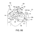
- This pivoting motion causes the open lever 151 to pivot also clockwise in FIG. 9B relative to the second coupling member 155. These cause a bottom surface of the protruding member 151c of the open lever 151 to rest on a top surface of the cradle 132 and further press down the cradle 132 to the package-removing position.
- the cradle opener 140 performs a lowering operation in this manner to lower the cradle 132 from the winding position to the package-removing position.
- the cradle opener 140 performs a raising operation by performing the lowering operation other way around.
- the cradle opener 140 is situated to cause the open lever 151 to press down the cradle 132 to the package-removing position so that a distal end of the swing portion 151b and the arm 132a of the cradle 132 intersect with each other.
- the swing portion 151b of the open lever 151 pivots toward the near side with reference to the plane of FIG. 10A via the linkage (not shown) relative to the support 151a, causing the arm 132a of the cradle 132 to move in the opening direction.
- the cradle opener 140 performs an opening operation of the cradle 132 by utilizing this pivoting motion of the open level 151. Performing the opening operation other way around moves the open lever 151 in the closing direction. The cradle 132 is also urged to move in the closing direction.
- the receiving mechanism 147 includes a driving motor 161, a pulley 163, and a receiving arm 164.
- the driving motor 161 is provided at a lower portion in the frame 160 and fixed to the frame 160. Driving force of the driving motor 161 is transmitted to the pulley 163 via the belt 162.
- the receiving arm 164 is coupled to the pulley 163 and pivotable about a coupling portion that couples the receiving arm 164 with the pulley 163.
- the receiving arm 164 has joints at two positions. When the doffing operation is not performed, the receiving arm 164 is placed at the retracting position in a state of being a substantially U-shaped and housed in the frame 160 by a linkage (not shown). As illustrated in FIG. 9B , when the doffing operation is to be performed, the driving motor 161 is driven to cause the receiving arm 164 to pivot about the coupling portion between the receiving arm 164 and the pulley 163, causing the two joints of the receiving arm 164 to be straightened in a substantially straight line with a distal end of the receiving arm 164 moving along the conveyer 146. The receiving arm 164 thus moves to a receiving position where the receiving arm 164 receives, from below, the package 117 held by the cradle 132 placed at the package-removing position.
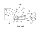
- the chuck mechanism 142 (winding-tube supplying unit) is provided between the winding-tube stocker 141, placed at an upper portion in the frame 160, and the receiving mechanism 147, placed at a lower portion in the frame 160.
- the chuck mechanism 142 includes a chuck arm 170 and a cylinder 171 that drives the chuck arm 170.
- the cylinder 171 is supported by a frame 172 fixed to the doffing apparatus 103 to be pivotable about a rotary shaft 173.
- the chuck arm 170 includes a first coupling member 175, a second coupling member 177, and a linking member 179.
- the first coupling member 175 is supported, at its basal end, by the frame 172 to be pivotable about a rotary shaft 174 and rotatably coupled, at a substantially longitudinal center portion of the first coupling member 175, to a rod 171a of the cylinder 171.
- the second coupling member 177 is rotatably coupled to a distal end of the first coupling member 175 and coupled, at a distal end of the second coupling member 177, to a holding unit 176 that holds the winding tube 133.
- the linking member 179 is supported, at its basal end, by the frame 172 to be pivotable about a rotary shaft 178 and rotatably coupled, at a distal end of the linking member 179, to the second coupling member 177.
- the chuck mechanism 142 When the doffing operation is not performed, as illustrated in FIG. 11A , the chuck mechanism 142 is placed at the retracting position where the rod 171a of the cylinder 171 has retracted and the winding tube 133 is not supplied to the cradle 132.
- the rod 171a of the cylinder 171 When the doffing operation is to be performed, as illustrated in FIG. 11B , the rod 171a of the cylinder 171 is advanced, causing the first coupling member 175 to pivot about the rotary shaft 174 relative to the frame 172 clockwise in FIG. 11B .
- This pivoting motion of the first coupling member 175 causes the linking member 179 to rotate the second coupling member 177 clockwise in FIG. 11B relative to the first coupling member 175.
- the suction pipe 144 is arranged in a left-hand portion, with reference to FIG. 7 , in the frame 160.
- the suction pipe 144 is configured such that actuating the driving motor 180 and the cylinder 181 causes a suction portion at a distal end of the suction pipe 144 to move to the position (a position indicated by a long dashed double-short dashed line in FIG. 8 ), to which the formed spun yarn 116 is to be delivered, downstream of the spinning device 107.
- the suction pipe 144 is configured such that, after the suction pipe 144 has sucked and caught the spun yarn 116 formed by the spinning device 107 at the position, the driving motor 180 and the cylinder 181 are driven to move the suction portion to a position where the yarn catching member 145 can pick up the spun yarn 116 being sucked and caught by the suction pipe 144.
- the cylinder 181 and a driving motor 182 that drive the chuck mechanism 142 and the yarn catching member 145 in the second embodiment correspond to the preparatory-unit driving source of the invention.
- the sensor 148 is an optical sensor fixed to the frame 160 and provided with a light-emitting unit and a light-receiving unit.
- the sensor 148 determines that the cradle 132 is holding the package 117.
- the sensor 148 determines that the cradle 132 is not holding the package 117. The result of this determination is transmitted to a doffing controller 193, which will be described later, of the doffing apparatus 103.
- FIG. 12 is a control block diagram of the spinning machine 100.
- each of the spinning units 102 includes a unit controller 192; the doffing apparatus 103 includes the doffing controller 193 (controlling unit).
- the unit controllers 192 and the doffing controller 193 are connected to the machine controller 191 through a communication network.
- the machine controller 191 performs centralized control of the spinning machine 100.
- the machine controller 191 transmits and receives signals to and from the unit controllers 192 of the spinning units 102 and the doffing controller 193 of the doffing apparatus 103 to perform operation control and status monitoring pertaining to the spinning units 102 and the doffing apparatus 103.
- the unit controllers 192 perform various control operations of the spinning units 102.
- the doffing controller 193 performs various control operations of the doffing apparatus 103.
- the doffing controller 193 is connected to the five cylinders 152, 156, 158, 171, and 181, the driving motors 161, 180, and 182, a driving motor 184, and the sensor 148.
- the cylinders 152, 156, and 158 drive the cradle opener 140.
- the driving motor 161 drives the receiving arm 164 of the receiving mechanism 147.
- the cylinder 171 drives the chuck arm 170 of the chuck mechanism 142.
- the driving motor 180 and the cylinder 181 drive the suction pipe 144.
- the driving motor 182 drives the yarn catching member 145.
- the driving motor 184 rotates a wheel 183 that causes the doffing apparatus 103 to slide in the direction along which the spinning units 102 are arranged in the row.
- the doffing controller 193 further includes a storing unit 194 that stores therein information about various modes that can be performed in the doffing apparatus 103 and a signal receiving unit 195 that receives signals from the machine controller 191.
- the storing unit 194 stores program codes for performing the doffing operation.
- the doffing controller 193 selectively performs operations in a first mode and a second mode.
- the first mode is a mode in which the doffing apparatus 103 performs reading of the program codes stored in the storing unit 194 and removing of the package 117, supplying of the winding tube 133, mounting of the winding tube 133, and attaching of the spun yarn 116.
- the second mode is a mode in which the doffing apparatus 103 performs only the removing of the package 117.
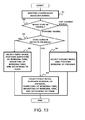
- FIG. 13 is a flowchart illustrating the operations performed by the doffing apparatus 103.
- the cradle 132 When winding of the spun yarn 116 is performed by the winding apparatus 112 of the spinning unit 102, the cradle 132 is placed at the winding position, and the package 117 held by the cradle 132 is brought into contact with the winding drum 118 so that the spun yarn 116 is wound on the package 117 rotated by rotation of the winding drum 118.
- the various mechanisms of the doffing apparatus 103 have retracted to the retracting position (see FIGS. 9A and 11A ).
- a doffing signal or a lot-change signal is transmitted from the unit controller 192 of the spinning unit 102 to the doffing controller 193 of the doffing apparatus 103 via the machine controller 191.
- the doffing apparatus 103 determines whether this signal is a doffing signal or a lot-change signal (Step S2).
- the doffing signal is a signal for causing, when the winding tube 133, on which winding is currently performed, is fully wound to become the fully-wound package 117, the package 117 to be removed, causing an empty winding tube 133, on which yarn is not wound, to be mounted, and causing winding of the spun yarn 116 on the winding tube 133 to be resumed.
- the lot-change signal is a signal for causing, after the winding tube 133 being currently wound has been fully wound, only the removal of the package 117 to be performed without scheduling another winding for a current lot.
- a lot change is to occur when a change in yarn type of the spun yarn 116, a change in winding condition, such as tension, or a change in type of the winding tube 133 is made.
- the doffing apparatus 103 slides on the rail 135 and stops in front of the spinning unit 102 that has issued the doffing signal; the sensor 148 determines whether the cradle 132 is holding the package 117 (Step S3). When the sensor 148 has determined that the cradle 132 is holding the package 117 (YES at Step S3), the doffing controller 193 selects the first mode. The doffing apparatus 103 performs the operations in the first mode (Step S4).
- the doffing apparatus 103 drives the driving motor 180 and the cylinder 181 to move the suction pipe 144 to a position downstream of the spinning device 107 so that the suction pipe 144 sucks and catches the spun yarn 116 formed by and delivered from the spinning device 107. This causes one of yarn ends, the one being connected to the spun yarn 116 wound on the package 117, to be wound on the package.
- the doffing apparatus 103 operates the cradle opener 140 to perform the lowering operation to thereby cause the open lever 151 to press down the cradle 132 to the package-removing position and operates the receiving mechanism 147 to thereby move the receiving arm 164 to the receiving position. This brings the package 117 held by the cradle 132 and coasting away from the winding drum 118 into contact with the receiving arm 164, which stops rotation of the package 117.
- the doffing apparatus 103 operates the cradle opener 140 to perform the opening operation so that the open lever 151 causes the arm 132a of the cradle 132 to pivot in the opening direction and the package 117 is removed from the cradle 132 and laid on the receiving arm 164.
- the doffing apparatus 103 drives the receiving mechanism 147 to move the receiving arm 164 to the retracting position. This causes the package laid on the receiving arm 164 to be discharged onto the conveyer 146 extending in the direction, along which the spinning units 102 are arranged in the row.
- the doffing apparatus 103 performs the removal of the package 117 in this manner.
- the doffing apparatus 103 operates the chuck mechanism 142 to move the chuck arm 170 to the supplying position to supply the winding tube 133 held by the holding unit 176 of the chuck arm 170 to the cradle 132 placed at the package-removing position with the arm 164 open. Thereafter, the doffing apparatus 103 operates the cradle opener 140 to perform the closing operation so that the open lever 151 causes the arm 132a of the cradle 132 to pivot in the closing direction to close the arm 132a of the cradle 132, thereby causing the cradle 132 to hold the winding tube 133. As illustrated in FIG.
- the doffing apparatus 103 moves the cradle opener 140 and the chuck mechanism 142 to the retracting position.
- the doffing apparatus 103 performs the supplying of the winding tube 133 and the mounting of the winding tube 133 in this manner.
- the doffing apparatus 103 drives the driving motor 180 and the cylinder 181 to thereby move the suction pipe 144 to the position where the yarn catching member 145 can pick up the spun yarn 116 being sucked and caught by the suction pipe 144, and operates the yarn catching member 145 to pick up the yarn and to thread the yarn to the position where a bunch winding is to be formed.
- the doffing apparatus 103 forms a bunch winding at an end of the winding tube 133. Subsequently, the doffing apparatus 103 causes the cradle 132 to move to the winding position.
- the doffing apparatus 103 causes the winding drum 118, which is in contact with the winding tube 133, to rotate to thereby resume winding of the spun yarn 116 delivered from the spinning device 107.
- the doffing apparatus 103 performs the attaching of the yarn to the winding tube 133 in this manner.
- the doffing operation in the first mode is performed by performing a sequence of operations including the removal of the package 117, the supplying and mounting of the winding tube 133, and the attaching of yarn to the winding tube 133.
- the doffing controller 193 selects the first mode.
- the doffing apparatus 103 performs the operations in the first mode except for the removal of the package 117 (Step S5). Examples of the situation where the cradle 132 is not holding the package 117 and the doffing apparatus 103 receives a doffing signal include a situation where winding is resumed after a lot change.
- the doffing apparatus 103 can perform operations in the first mode while skipping the removal of the package 117 depending on a result of determination obtained by the sensor 148 as to whether the cradle 132 is holding the package 117. If the cradle 132 is not holding the package 117, the doffing apparatus 103 performs only the mounting of the winding tube 133 without performing the removal of the package 117.
- the doffing apparatus 103 slides on the rail 135 and stops at a position in front of the spinning units 102 that has issued the lot-change signal.
- the doffing controller 193 selects the second mode.
- the doffing apparatus 103 performs the operations in the second mode (Step S6).
- the doffing apparatus 103 performs only the removal of the package 117 from the cradle 132. Accordingly, the supplying of the winding tube 133 and the mounting of the winding tube are skipped. This eliminates the need of manually removing the winding tube 133 that has been unnecessarily mounted on the 132 after removal of the package 117.
- the doffing apparatus 103 includes driving sources that are individually provided for and capable of independently driving the cradle opener 140 that operates the cradle 132, the receiving mechanism 147 that receives the fully-wound package 117, the chuck mechanism 142 that delivers the winding tube 133, the suction pipe 144 that sucks and catches the spun yarn 116 when a bunch winding is to be formed, and the yarn catching member 145 that picks up the spun yarn 116 sucked and caught by the suction pipe 144. Accordingly, the doffing apparatus 103 according to the second embodiment can perform only one or more operations according to a circumstance, and can perform only minimum operation by omitting unnecessary operations and the like. This leads to efficient doffing operation achieving reduction in the cycle time and the like.
- the doffing apparatus 103 can perform only one or more necessary operations by omitting unnecessary operations because the doffing controller 193 selects an appropriate mode according to a circumstance.
- the doffing apparatus 3 includes the doffing controller 42 that controls the driving sources, such as the fluid pressure cylinder 38 and the driving motor 52; however, an alternative configuration is allowable in which the doffing apparatus 3 does not include such a controller and these driving sources are controlled by the machine controller 191 or the unit controller 192.
- the doffing apparatus 103 includes the doffing controller 42 that controls the driving sources that drives the various mechanism of the doffing apparatus 103; an alternative configuration is allowable in which the doffing apparatus 103 does not include such a controller and these driving sources are controlled by the machine controller 191 or the unit controller 192.
- the driving source that performs the opening/closing operation of the cradle opener 32 is not limited to the fluid pressure cylinder but can be a driving motor.
- the driving source that performs the raising/lowering operation of the cradle opener 32 is not limited to the driving motor and can be a fluid pressure cylinder.
- the sensor 51 that determines whether the cradle 12 is holding the package 6 is not necessarily provided on the doffing apparatus 3 but can be provided on the winding unit 2.
- the sensor 148 can be provided on the spinning unit 102 rather than on the doffing apparatus 103.
- the single open lever 37 of the cradle opener 32 serves as the lever performing the opening/closing operation of the cradle 12 and as the lever performing the raising/lowering operation of the cradle 12; however, an alternative configuration is allowable in which different levers are provided separately for the opening/closing operation and for the raising/lowering operation.
- the single open lever 151 of the cradle opener 140 serves as the lever performing the opening/closing operation of the cradle 132 and as the lever performing the raising/lowering operation of the cradle 132; however, an alternative configuration is allowable in which different levers are provided separately for the opening/closing operation and for the raising/lowering operation can be employed.
- the doffing apparatus separately includes a driving source for driving the operating unit and a driving source for driving the winding-tube supplying unit and the yarn guiding unit.
- This configuration makes it possible to perform the situation-sensitive required operations. Moreover, it is possible to skip the unnecessary operations, and perform only the least required operations. Furthermore, because the cycle time and the like can be shortened, it is possible to provide a doffing apparatus capable of efficiently performing the doffing operation. Moreover, it is possible to skip the unnecessary operations as per situations and perform only the least required operations. In addition, this configuration leads to a lengthening of operating lives of parts and reduces the chances of occurrence of troubles such as a failure.
- a removal operation of removing the package from the winding-tube holding unit includes raising the winding-tube holding unit and opening the winding-tube holding unit, and a mounting operation of mounting the winding unit onto the winding-tube holding unit includes lowering the winding-tube holding unit and closing the winding-tube holding unit.
- the operating unit is operative to both open or close and raise or lower the winding-tube holding unit.
- the operating-unit driving source includes a first driving source that is operative to open or close the winding-tube holding unit, and a second driving source that is operative to raise or lower the winding-tube holding unit.
- the doffing apparatus includes a controlling unit that controls the first driving source and the second driving source, the controlling unit drives the second driving source based on a set value set in advance thereby causing the operating unit to raise or lower the winding-tube holding unit and drives the first driving source thereby causing the operating unit to open or close the winding-tube holding unit thereby performing the removal operation of the package.
- the controlling unit drives the second driving source based on a set value set in advance thereby causing the operating unit to raise or lower the winding-tube holding unit and drives the first driving source thereby causing the operating unit to open or close the winding-tube holding unit thereby performing the removal operation of the package.
- the doffing apparatus includes a signal receiving unit that receives a shape signal indicative of a current shape of the winding tube from the winding apparatus and a storing unit that stores therein movement amounts of the winding-tube holding unit corresponding to various shapes of the winding tube, and the controlling unit acquires from the storing unit a movement amount of the winding-tube holding unit corresponding to the current shape of the winding tube indicated in the shape signal, and drives the second driving source based on the acquired movement amount thereby performing the removal operation of the package.
- the movement amount of the winding-tube holding unit can be changed depending on the current shape of the winding unit. Therefore, the removal operation that is appropriate to the current shape of the package can be performed.
- the controlling unit controls the operating-unit driving source and the preparatory-unit driving source, and the controlling unit is capable of selecting one between a first mode and a second mode.
- the first mode being an action of controlling driving of the operating-unit driving source and the preparatory-unit driving source by operating the operating unit to perform the removal operation of removing the package from the winding-tube holding unit, a supplying operation of supplying the winding tube to the winding-tube holding unit by the winding-tube supplying unit, and a guiding operation of guiding the yarn to the winding tube by the yarn guiding unit
- the second mode being an action of controlling driving of the operating-unit driving source by operating the operating unit to perform the removal operation of removing the package from the winding-tube holding unit.
- the doffing apparatus includes a sensor that determines whether the winding-tube holding unit is holding a package, the signal receiving unit receives a doffing signal from the winding apparatus, and the controlling unit selects the first mode upon the signal receiving unit receiving the doffing signal.
- controlling unit after selecting the first mode and upon the sensor determining that the package has been held by the winding-tube holding unit, controls driving of the operating-unit driving source and the preparatory-unit driving source to perform the removal operation, the supplying operation, and the guiding operation
- controlling unit after selecting the first mode and upon the sensor determining that a package is not held by the winding-tube holding unit, controls driving of the preparatory-unit driving source to perform the supplying operation and the guiding operation.
- the winding-tube holding unit is not holding a package, only the preparatory-unit driving source is driven, i.e., the operating-unit driving source is not driven, and only mounting of the winding tube is performed, i.e., removing of the package is not performed.
- the signal receiving unit also receives a lot-change signal, and the controlling unit selects the second mode upon the signal receiving unit receiving the lot-change signal. Moreover, the controlling unit, after selecting the second mode, controls driving of the operating-unit driving source to perform only the removal operation.
- the doffing apparatus separately includes a driving source for driving the operating unit and a driving source for driving the winding-tube supplying unit and the yarn guiding unit. Therefore, it possible to perform only the situation-sensitive required operations, skip the unnecessary operations, and perform only the least required operations. Moreover, the cycle time can be shortened, and the doffing operation can be performed efficiently.
Landscapes
- Engineering & Computer Science (AREA)
- Mechanical Engineering (AREA)
- Textile Engineering (AREA)
- Spinning Or Twisting Of Yarns (AREA)
- Replacing, Conveying, And Pick-Finding For Filamentary Materials (AREA)
Applications Claiming Priority (2)
| Application Number | Priority Date | Filing Date | Title |
|---|---|---|---|
| JP2010007385 | 2010-01-15 | ||
| JP2010126031A JP2011162351A (ja) | 2010-01-15 | 2010-06-01 | 玉揚げ装置 |
Publications (2)
| Publication Number | Publication Date |
|---|---|
| EP2345612A2 true EP2345612A2 (de) | 2011-07-20 |
| EP2345612A3 EP2345612A3 (de) | 2015-03-18 |
Family
ID=43901160
Family Applications (1)
| Application Number | Title | Priority Date | Filing Date |
|---|---|---|---|
| EP11150362.9A Withdrawn EP2345612A3 (de) | 2010-01-15 | 2011-01-07 | Abziehvorrichtung |
Country Status (3)
| Country | Link |
|---|---|
| EP (1) | EP2345612A3 (de) |
| JP (1) | JP2011162351A (de) |
| CN (1) | CN102126647B (de) |
Cited By (8)
| Publication number | Priority date | Publication date | Assignee | Title |
|---|---|---|---|---|
| CN102540936A (zh) * | 2012-03-03 | 2012-07-04 | 南昌航空大学 | 基于fpga自动落纱机器控制装置 |
| CN103696059A (zh) * | 2013-12-31 | 2014-04-02 | 东华大学 | 一种自动落纱系统的机械手系统 |
| EP2907780A1 (de) * | 2014-02-12 | 2015-08-19 | Murata Machinery, Ltd. | Spuleneinstellungsvorrichtung und Garnwickelmaschine |
| CN111099438A (zh) * | 2020-01-08 | 2020-05-05 | 欧阳五湖 | 一种用于对绕线盘进行加装的方法 |
| EP4101801A1 (de) * | 2021-06-11 | 2022-12-14 | Saurer (Jiangsu) Textile Machinery Co. Ltd. | Abnahmevorrichtung, abnahmesteuerverfahren und abnahmesteuergerät |
| CN116331954A (zh) * | 2021-12-23 | 2023-06-27 | 合肥松宝科技有限公司 | 一种满丝筒换向机构及换向方法 |
| CN117448997A (zh) * | 2023-11-20 | 2024-01-26 | 卓郎(江苏)纺织机械有限公司 | 一种抓管及推纱喂管机构 |
| CN119079711A (zh) * | 2024-07-22 | 2024-12-06 | 青岛宏大纺织机械有限责任公司 | 一种络筒机的智能换批控制系统及络筒机换批方法 |
Families Citing this family (19)
| Publication number | Priority date | Publication date | Assignee | Title |
|---|---|---|---|---|
| JP2012086923A (ja) * | 2010-10-18 | 2012-05-10 | Murata Machinery Ltd | 玉揚装置及びそれを備える糸巻取機 |
| JP2013063808A (ja) * | 2011-09-15 | 2013-04-11 | Murata Machinery Ltd | クレードル、巻取ユニット、及び糸巻取機 |
| JP2013063841A (ja) * | 2011-09-20 | 2013-04-11 | Murata Machinery Ltd | 玉揚装置及びそれを備えた繊維機械 |
| JP2014227249A (ja) | 2013-05-21 | 2014-12-08 | 村田機械株式会社 | 糸巻取機 |
| CN103526364B (zh) * | 2013-10-18 | 2015-10-07 | 陕西华燕航空仪表有限公司 | 落筒机械手 |
| JP2015101453A (ja) * | 2013-11-26 | 2015-06-04 | 村田機械株式会社 | ボビン保持装置、ボビンセット装置及び糸巻取機 |
| JP2015147674A (ja) * | 2014-02-10 | 2015-08-20 | 村田機械株式会社 | 玉揚装置及びこれを備えた糸巻取機 |
| CN105088447B (zh) * | 2014-05-14 | 2017-08-25 | 高密市元裕机械科技有限公司 | 自动落纱机 |
| CN105908295B (zh) * | 2016-03-09 | 2018-08-21 | 安徽日发纺织机械有限公司 | 一种气流纺纱机落纱小车 |
| IT201600071598A1 (it) * | 2016-07-08 | 2018-01-08 | Savio Macch Tessili Spa | Metodo di levata in una macchina di filatura di tipo open-end |
| CN106381584B (zh) * | 2016-08-31 | 2018-11-02 | 山东同大机械有限公司 | 自动落纱装置及包含该装置的细纱机的落纱方法 |
| CN108588917B (zh) * | 2018-05-16 | 2021-04-20 | 东华大学 | 一种转杯纺纱机自动落纱小车 |
| CN108842236B (zh) * | 2018-05-16 | 2021-03-02 | 东华大学 | 转杯纺筒子架抬起与打开装置 |
| JP2020179985A (ja) * | 2019-04-26 | 2020-11-05 | 村田機械株式会社 | 糸巻取機及び糸掛け方法 |
| CN111441112B (zh) * | 2020-05-09 | 2024-12-03 | 浙江日发纺机技术有限公司 | 一种纺纱装置及其自动落纱和上纱方法 |
| CN111960189B (zh) * | 2020-08-31 | 2024-08-02 | 四川大学 | 自动卷纱设备 |
| JP7681433B2 (ja) | 2021-05-31 | 2025-05-22 | Tmtマシナリー株式会社 | 空紙管供給装置を有する仮撚加工機 |
| JP2023142771A (ja) * | 2022-03-25 | 2023-10-05 | 村田機械株式会社 | 糸巻取機及び糸巻取方法 |
| JP2023145987A (ja) * | 2022-03-29 | 2023-10-12 | 村田機械株式会社 | 糸巻取機及び糸巻取方法 |
Citations (3)
| Publication number | Priority date | Publication date | Assignee | Title |
|---|---|---|---|---|
| JP2005219880A (ja) | 2004-02-06 | 2005-08-18 | Murata Mach Ltd | バンチ巻方法及びバンチ巻装置を備えた紡績機 |
| JP2008162712A (ja) | 2006-12-27 | 2008-07-17 | Murata Mach Ltd | 玉揚装置およびそれを備えた繊維機械 |
| JP2009084023A (ja) | 2007-10-02 | 2009-04-23 | Murata Mach Ltd | 繊維機械 |
Family Cites Families (6)
| Publication number | Priority date | Publication date | Assignee | Title |
|---|---|---|---|---|
| DE19935695A1 (de) * | 1999-07-29 | 2001-02-01 | Stahlecker Fritz | Verfahren zum Umrüsten und gleichzeitigen Modernisieren einer Offenend-Rotorspinnmaschine |
| JP3646682B2 (ja) * | 2001-02-28 | 2005-05-11 | 村田機械株式会社 | 自動ワインダにおける巻取管への糸装着方法及び自動ワインダ |
| JP2006225092A (ja) * | 2005-02-16 | 2006-08-31 | Murata Mach Ltd | 自動玉揚げ動作方法 |
| JP4487942B2 (ja) * | 2005-05-10 | 2010-06-23 | 村田機械株式会社 | 自動ワインダーの玉揚げ装置 |
| JP2007320684A (ja) * | 2006-05-31 | 2007-12-13 | Murata Mach Ltd | 繊維機械 |
| DE102007036696A1 (de) * | 2007-08-03 | 2009-02-05 | Oerlikon Textile Gmbh & Co. Kg | Kreuzspulenwechsler |
-
2010
- 2010-06-01 JP JP2010126031A patent/JP2011162351A/ja active Pending
- 2010-12-17 CN CN201010600419.2A patent/CN102126647B/zh active Active
-
2011
- 2011-01-07 EP EP11150362.9A patent/EP2345612A3/de not_active Withdrawn
Patent Citations (3)
| Publication number | Priority date | Publication date | Assignee | Title |
|---|---|---|---|---|
| JP2005219880A (ja) | 2004-02-06 | 2005-08-18 | Murata Mach Ltd | バンチ巻方法及びバンチ巻装置を備えた紡績機 |
| JP2008162712A (ja) | 2006-12-27 | 2008-07-17 | Murata Mach Ltd | 玉揚装置およびそれを備えた繊維機械 |
| JP2009084023A (ja) | 2007-10-02 | 2009-04-23 | Murata Mach Ltd | 繊維機械 |
Cited By (9)
| Publication number | Priority date | Publication date | Assignee | Title |
|---|---|---|---|---|
| CN102540936A (zh) * | 2012-03-03 | 2012-07-04 | 南昌航空大学 | 基于fpga自动落纱机器控制装置 |
| CN103696059A (zh) * | 2013-12-31 | 2014-04-02 | 东华大学 | 一种自动落纱系统的机械手系统 |
| CN103696059B (zh) * | 2013-12-31 | 2016-01-06 | 东华大学 | 一种自动落纱系统的机械手系统 |
| EP2907780A1 (de) * | 2014-02-12 | 2015-08-19 | Murata Machinery, Ltd. | Spuleneinstellungsvorrichtung und Garnwickelmaschine |
| CN111099438A (zh) * | 2020-01-08 | 2020-05-05 | 欧阳五湖 | 一种用于对绕线盘进行加装的方法 |
| EP4101801A1 (de) * | 2021-06-11 | 2022-12-14 | Saurer (Jiangsu) Textile Machinery Co. Ltd. | Abnahmevorrichtung, abnahmesteuerverfahren und abnahmesteuergerät |
| CN116331954A (zh) * | 2021-12-23 | 2023-06-27 | 合肥松宝科技有限公司 | 一种满丝筒换向机构及换向方法 |
| CN117448997A (zh) * | 2023-11-20 | 2024-01-26 | 卓郎(江苏)纺织机械有限公司 | 一种抓管及推纱喂管机构 |
| CN119079711A (zh) * | 2024-07-22 | 2024-12-06 | 青岛宏大纺织机械有限责任公司 | 一种络筒机的智能换批控制系统及络筒机换批方法 |
Also Published As
| Publication number | Publication date |
|---|---|
| EP2345612A3 (de) | 2015-03-18 |
| CN102126647B (zh) | 2014-07-02 |
| JP2011162351A (ja) | 2011-08-25 |
| CN102126647A (zh) | 2011-07-20 |
Similar Documents
| Publication | Publication Date | Title |
|---|---|---|
| CN1028039C (zh) | 在气流纺纱装置中连接纱线的方法和装置 | |
| JP6080153B2 (ja) | 紡績機及び紡績機における糸の製造を中断する方法 | |
| JP2011162351A (ja) | 玉揚げ装置 | |
| EP1460015B1 (de) | Spulmaschine für Faden | |
| EP2479129B1 (de) | Garnwicklungsmaschine | |
| JP5190703B2 (ja) | 糸巻取装置及び自動ワインダ | |
| JPH01203177A (ja) | スプール交換の際に糸を案内、保持及び切断する方法及び装置 | |
| JP6176952B2 (ja) | オートワインダの作業部の巻取り速度を最適化する方法 | |
| EP2573217B1 (de) | Spinneinheit, Spinnmaschine und Garnverarbeitungsverfahren | |
| CN109969861B (zh) | 纱线卷取机以及筒管供给方法 | |
| CN1080331C (zh) | 在气流纺纱机上纱线生头的方法以及装置 | |
| US20080283655A1 (en) | Method and device for operating a winding device of a textile machine producing cross-wound bobbins | |
| EP2075358A2 (de) | Spinnmaschine | |
| EP2072440A2 (de) | Abspulhilfsvorrichtung und automatischer Wickler damit | |
| CN107963518B (zh) | 纱线卷取装置以及接头方法 | |
| CN102249120B (zh) | 制造管纱的方法 | |
| JPH10167577A (ja) | 綾巻きパッケージを製造する繊維機械の巻返しユニット | |
| CN105764823B (zh) | 变形机和用于操作变形机的卷绕站的方法 | |
| CN109969862A (zh) | 纱线卷取机 | |
| CN107963512B (zh) | 纱线卷取装置以及卷装的旋转停止方法 | |
| JP2015009965A (ja) | 自動ワインダ | |
| US10907278B2 (en) | Method for automatically piecing a thread at a workstation of a textile machine, and textile machine | |
| CN116803878A (zh) | 纱线卷取机以及纱线卷取方法 | |
| CN111847101B (zh) | 纱线卷取机及挂纱方法 | |
| JP2016000658A (ja) | 巻き取り装置を備える繊維機械 |
Legal Events
| Date | Code | Title | Description |
|---|---|---|---|
| PUAI | Public reference made under article 153(3) epc to a published international application that has entered the european phase |
Free format text: ORIGINAL CODE: 0009012 |
|
| AK | Designated contracting states |
Kind code of ref document: A2 Designated state(s): AL AT BE BG CH CY CZ DE DK EE ES FI FR GB GR HR HU IE IS IT LI LT LU LV MC MK MT NL NO PL PT RO RS SE SI SK SM TR |
|
| AX | Request for extension of the european patent |
Extension state: BA ME |
|
| PUAL | Search report despatched |
Free format text: ORIGINAL CODE: 0009013 |
|
| AK | Designated contracting states |
Kind code of ref document: A3 Designated state(s): AL AT BE BG CH CY CZ DE DK EE ES FI FR GB GR HR HU IE IS IT LI LT LU LV MC MK MT NL NO PL PT RO RS SE SI SK SM TR |
|
| AX | Request for extension of the european patent |
Extension state: BA ME |
|
| RIC1 | Information provided on ipc code assigned before grant |
Ipc: B65H 54/26 20060101ALI20150209BHEP Ipc: D01H 13/00 20060101ALI20150209BHEP Ipc: D01H 9/10 20060101ALI20150209BHEP Ipc: B65H 67/04 20060101AFI20150209BHEP |
|
| 17P | Request for examination filed |
Effective date: 20150909 |
|
| RBV | Designated contracting states (corrected) |
Designated state(s): AL AT BE BG CH CY CZ DE DK EE ES FI FR GB GR HR HU IE IS IT LI LT LU LV MC MK MT NL NO PL PT RO RS SE SI SK SM TR |
|
| 17Q | First examination report despatched |
Effective date: 20160927 |
|
| STAA | Information on the status of an ep patent application or granted ep patent |
Free format text: STATUS: THE APPLICATION HAS BEEN WITHDRAWN |
|
| 18W | Application withdrawn |
Effective date: 20161215 |