EP2346091A2 - Unité de raccordement pour modules photovoltaïques - Google Patents
Unité de raccordement pour modules photovoltaïques Download PDFInfo
- Publication number
- EP2346091A2 EP2346091A2 EP11151233A EP11151233A EP2346091A2 EP 2346091 A2 EP2346091 A2 EP 2346091A2 EP 11151233 A EP11151233 A EP 11151233A EP 11151233 A EP11151233 A EP 11151233A EP 2346091 A2 EP2346091 A2 EP 2346091A2
- Authority
- EP
- European Patent Office
- Prior art keywords
- glass
- temperature
- solar module
- glass sheet
- solar cell
- Prior art date
- Legal status (The legal status is an assumption and is not a legal conclusion. Google has not performed a legal analysis and makes no representation as to the accuracy of the status listed.)
- Withdrawn
Links
Images

Classifications
-
- H—ELECTRICITY
- H10—SEMICONDUCTOR DEVICES; ELECTRIC SOLID-STATE DEVICES NOT OTHERWISE PROVIDED FOR
- H10F—INORGANIC SEMICONDUCTOR DEVICES SENSITIVE TO INFRARED RADIATION, LIGHT, ELECTROMAGNETIC RADIATION OF SHORTER WAVELENGTH OR CORPUSCULAR RADIATION
- H10F77/00—Constructional details of devices covered by this subclass
- H10F77/93—Interconnections
- H10F77/933—Interconnections for devices having potential barriers
- H10F77/935—Interconnections for devices having potential barriers for photovoltaic devices or modules
- H10F77/939—Output lead wires or elements
-
- H—ELECTRICITY
- H10—SEMICONDUCTOR DEVICES; ELECTRIC SOLID-STATE DEVICES NOT OTHERWISE PROVIDED FOR
- H10F—INORGANIC SEMICONDUCTOR DEVICES SENSITIVE TO INFRARED RADIATION, LIGHT, ELECTROMAGNETIC RADIATION OF SHORTER WAVELENGTH OR CORPUSCULAR RADIATION
- H10F19/00—Integrated devices, or assemblies of multiple devices, comprising at least one photovoltaic cell covered by group H10F10/00, e.g. photovoltaic modules
- H10F19/80—Encapsulations or containers for integrated devices, or assemblies of multiple devices, having photovoltaic cells
-
- Y—GENERAL TAGGING OF NEW TECHNOLOGICAL DEVELOPMENTS; GENERAL TAGGING OF CROSS-SECTIONAL TECHNOLOGIES SPANNING OVER SEVERAL SECTIONS OF THE IPC; TECHNICAL SUBJECTS COVERED BY FORMER USPC CROSS-REFERENCE ART COLLECTIONS [XRACs] AND DIGESTS
- Y02—TECHNOLOGIES OR APPLICATIONS FOR MITIGATION OR ADAPTATION AGAINST CLIMATE CHANGE
- Y02E—REDUCTION OF GREENHOUSE GAS [GHG] EMISSIONS, RELATED TO ENERGY GENERATION, TRANSMISSION OR DISTRIBUTION
- Y02E10/00—Energy generation through renewable energy sources
- Y02E10/50—Photovoltaic [PV] energy
Definitions
- the present invention relates to a solar module for converting radiant energy, in particular of sunlight, into electrical energy, comprising a solar cell for converting radiant energy into electrical energy, an electrical conductor for conducting the electrical energy and an encapsulation surrounding the solar cell for protecting the solar cell the encapsulant comprises one or more glass sheets for protecting and stabilizing the solar cell and a layer of potting material into which the solar cell is laminated or cast. Furthermore, the invention relates to a method for producing a corresponding solar module.
- the solar cells In order to operate solar cells as efficiently as possible, they must be exposed to sunlight for as long as possible, so they are installed outdoors and without shadowing, for example of buildings or trees. There, however, they are exposed to a variety of external influences, such as dirt particles, hail, temperature fluctuations and corrosive media. Furthermore, the solar cells can be damaged during assembly or maintenance. They are therefore encapsulated to protect them from these influences and to ensure electrical safety.
- the essential components of an encapsulation in addition to the glass pane, which is arranged in the direction of the incident rays in front of the solar cell, and the layer of potting material, a film on the back of the solar cell, which can alternatively be replaced by a further glass sheet.
- the potting material is a transparent plastic, for example ethylene vinyl acetate (EVA) or silicone rubber.
- the solar cells and the encapsulation form part of a solar module, which further usually includes a junction box and profile frame, for example made of aluminum, steel or fiber-reinforced plastic, for protecting the glass pane during transport, handling and assembly and for fastening and stiffening of the solar module.
- a junction box and profile frame for example made of aluminum, steel or fiber-reinforced plastic, for protecting the glass pane during transport, handling and assembly and for fastening and stiffening of the solar module.
- the glass sheets used in a solar module are usually made of soda-silica glasses having a thickness of several millimeters in order to give the required rigidity to the solar module.
- the glass sheets may be provided with an antireflection coating to prevent the sun from being reflected in the solar panels, which could cause irritation to aircraft, for example.
- silicon As a starting material of solar cells, silicon is used in most cases, which is mainly used in two different configurations: Firstly, crystalline silicon (c-Si) and on the other amorphous silicon (a-Si) is used.
- c-Si crystalline silicon
- a-Si amorphous silicon
- Monocrystalline and polycrystalline solar cells usually have a square format with a size of about 15 x 15 cm. They are sawn off the drawn or cast silicon blocks with special saws. Monocrystalline silicon solar cells can be recognized by their uniform, smooth surface and the broken corners, which are due to the manufacturing process. They are in fact cut out of round discs, which in turn owe their round shape to the blocks pulled by the Czochralski method.
- polycrystalline solar cells are as square as the cast blocks from which they are sawn out. They have an irregular surface, on which clearly the crystallites are seen from a few millimeters to a few centimeters in diameter.
- the technically possible thickness of these sawn slices is usually about 0.2 mm.
- the decisive factor for the amount of electrical energy converted from the radiant energy is namely the area of the solar cell and not its thickness, so that the possibility of producing thinner slices brings a cost advantage since it allows much more slices to be obtained from the same silicon block.
- Amorphous silicon has no crystal structure, but consists of disordered silicon atoms, which are vapor-deposited on glass or another substrate.
- Amorphous silicon has a high absorption capacity and can therefore be used in solar cells with particularly low layer thicknesses.
- the usual layer thicknesses are about a factor of 100 smaller than in crystalline silicon. This compensates for the low efficiency of about 6 to 8% due to the defects and makes amorphous silicon economically attractive for applications in the solar industry.
- electrical conductors In order to lead electrical lines to the solar cells and to be able to remove the electrical energy provided by them, electrical conductors must be installed in the solar module. For this it is for example from the DE 102 25 140 A1 known to drill holes in the glass pane at certain points on the back of the solar module. In case the back is formed with foil, the holes are not drilled but punched in the foil. The electrical conductor can be routed out of the solar module through these holes and connected to external circuits.
- the conductors can be embodied, for example, in the form of solder strips, via which the solar cells or entire solar modules are interconnected.
- solder strips usually 8 to 12 series-connected solar cells are combined into a string.
- the soldering tapes are usually laid U-shaped, so that two adjacent strings are combined into one unit.
- a diode is switched, which poles in the normal operating state (solar cell provides power) in the reverse direction. If a solar cell does not provide power through shadowing or a defect, the now reverse-biased diodes would shut down a string consisting of multiple series-connected solar cells. exceeds the voltage of the series-connected functional and irradiated solar cells the blocking voltage of the non-irradiated solar cell, this can even be destroyed. This is prevented by the diodes.
- a string can therefore also supply electrical energy in this case, albeit to a lesser extent.
- an electrode system is arranged in a piston which stands on a Pressglasfuß. Two electrical conductors are guided through the Pressglasfuß. The point of implementation is sealed with glass solder.
- the DE 761 322 does not affect solar modules.
- the DE 30 47 399 A1 relates to a method for mechanical and electrical connection of encapsulated solar cell generators with outer leads. This involves specifying a conductive connection through the encapsulation material so that the electrical energy provided by a solar cell can be transferred to a cable via a connecting element and forwarded.
- the in the DE 30 47 399 A1 The invention disclosed does not relate to passage through glass panes.
- the drilled holes for passing the electrical conductors have the disadvantage of weakening the glass sheet, thereby decreasing their strength and bearing capacity.
- Both in the design of the back with a glass sheet as well as with a film further has the disadvantage that the holes allow the entry of surrounding media such as dust particles, moisture and corrosive gases such as ammonia when used in livestock systems, since the holes with the conductors do not seal. These media can damage the solar cells and lead to a significant reduction in their lifetime.
- Object of the present invention is therefore to further develop solar modules of the type mentioned so that the provided by the solar cells electrical energy can be dissipated in a mechanically reliable and permanently sealed manner from the solar module without tangibly complicating the manufacturing process of the relevant solar module.
- the object is achieved by a fused into the glass body for guiding the electrical energy through the glass or for passing the electrical conductor through the glass.
- the electrical system is usually removed from the solar module at the rear, it is just as possible to do so at the front of the solar module.
- the body can therefore be melted into a glass pane on the front as well as on the back of the module or in both glass panes.
- the fact that the body is melted into the glass it is ensured that the contact surface between the glass and the body is permanently sealed so that no media, especially liquids and corrosive gases can penetrate into the solar module.
- the solar cells are therefore protected from these media, so that their life can be extended.
- the body forms a bond with the glass so that, unlike drilled holes, it is not mechanically weakened.
- the strength and the load-bearing capacity of the glass pane are not reduced, so that the solar module as a whole can be subject to greater mechanical stress.
- the glass plate can be biased, which is then used according to the invention for the fixation of the body. This bias is not lost by the inventive melting of the body.
- the body is designed as an electrically conductive pin, which is conductively connected to the electrical conductor.
- the body is thus integrated into the dissipation of the electrical energy from the solar module.
- This design is particularly easy to manufacture and therefore inexpensive to implement.
- the electrical conductors need only be attached to both sides of the body, for example by soldering.
- the body must therefore be made of electrically conductive material such as metal, which, however, anyway represents a widely used material for pens, so that this restriction brings no technical disadvantage.
- the pin is designed as a cylindrical pin, taper pin or bolt with head.
- standard parts can be used, which are produced in large quantities and are therefore available at low cost.
- Cone pins and bolts with head have the further advantage that their position is at least largely fixed in one direction, so that they can be better brought to the desired position during melting. Furthermore, the risk of slipping during melting reduces.
- the body has a through hole for passing the electrical conductor through the body and through the glass pane.
- the electrical conductor does not need to be electrically connected to the body, so that it can be continuously guided from the solar module to adjacent circuits.
- the body comprises a thread into which a screw for electrically conductive connection of the electrical conductor to the body can be screwed.
- the electrically conductive connection can be made in a simple manner, while at the same time, for example, compared to solder joints, is very strong.
- the thread is oriented so that the screw from the front of the solar module, so from the direction of the incident rays, is screwed into the thread. This has the advantage that the screw connection is easily accessible and visible. This simplifies assembly and helps to identify and correct errors in the wiring of the solar module.
- the solar module according to the invention has a further encapsulation for protecting the electrical conductor and securing the screw.
- the encapsulating material of the further encapsulation may correspond to that of the encapsulation.
- the further encapsulation is designed so that it encloses the screw and partially the electrical conductor.
- the body, the thread and the screw can be protected from external influences, in particular weather conditions, on the other hand, the electrical conductor can be protected from mechanical influences, such as tensile loads, if the further encapsulation is formed accordingly. Furthermore, a loosening of the screw can be prevented.
- the body is made of non-conductive material and has a through hole for passing the electrical conductor through the body and through the glass.
- the materials can be selected, for example, so that their thermal expansion coefficient can be adapted to that of the glass. This can be advantageously used in the melting process to induce targeted stresses in the glass that hold the body safely and permanently in the glass.
- the glass transition or softening temperature T G separates the underlying brittle energy-elastic range from the above soft entropy-elastic range of the relevant glass.
- the body can be guided through the glass pane with relatively little effort, without damaging the glass pane, in particular without it breaking.
- the body can be performed with the aid of a suitable tool through the heated glass.
- the second temperature can be well above the glass transition temperature, but care must be taken that it is not so high that the glass is not permanently changed, for example by segregation, devitrification or evaporation.
- the first temperature is the room temperature, but it is also possible to choose a different temperature from which the glass sheet is heated to the second temperature.
- the third temperature is usually the room temperature, so that the first temperature may be equal to the third, but not necessarily. It may be beneficial to the
- the method according to the invention is further developed in that the glass pane is heated in a passage area within which the body is passed through the glass pane.
- the term "lead-through area” is understood to mean an area which surrounds the point at which the body is guided through the glass pane.
- An exact spatial limitation of the lead-through area should not be made here, since its spatial spread depends on many factors such as the glass used and / or the height of the second temperature. However, it can be said that preferably the center of the lead-through area is located approximately at the longitudinal axis of the body.
- the heating of only this lead-through area has the advantage that not all the glass has to be heated, which is energetically favorable and facilitates the handling of the glass plate during the melting of the body.
- the latter is due in particular to the fact that the glass plate as a whole is still firm and soft and thus deformable only in the lead-through area.
- the lead-through area can be heated with a gas flame or with a CO 2 laser, wherein the temperature of the glass pane can be measured and controlled in the lead-through area, for example with a pyrometer, pyranometer or pyrheliometer.
- the local heating of the lead-through area has the advantage that the bias of the glass plate is maintained.
- the glass pane is heated on both glass surfaces.
- disks represent bodies that are distinguished by having two opposite surfaces which are significantly larger than the remaining or remaining surfaces. The same applies to the glass panes used here.
- both glass surfaces are heated at the same time, on the one hand accelerate the heating of the glass pane or the lead-through area and on the other hand creates a more uniform temperature profile within the glass plate. It is thus the danger reduces the fact that portions of the glass in the lead-through area have a temperature below the softening temperature, which could lead to damage of the glass pane during the passage of the body.
- the method according to the invention is further developed in that the glass pane is forcibly cooled from the second to the third temperature.
- the manufacturing process can be accelerated because the time required for cooling is reduced.
- stresses are induced in the glass pane in the passage area of the melted body in a targeted manner, which act on them and connect them more firmly to the glass pane. A loosening and a possible detachment of the body from the glass sheet are thus largely prevented.
- body temperature is to be understood as meaning the temperature of the body which according to the invention is melted into the glass pane.
- a connection with the temperature of the human body can not be derived here.
- the term is used to distinguish from the temperature of the glass sheet.
- the second body temperature can be chosen lower than the second temperature of the glass. This is advantageous if the thermal expansion coefficient of the material from which the body is made, is higher than that of the glass used. Upon cooling, the glass is shrunk onto the body to induce stresses in the glass sheet which act on the body in the cooled state and hold it in the glass sheet.
- the second body temperature can be set higher than the second temperature of the glass sheet. This is advantageous if the thermal expansion coefficient of the material of which the body is made is lower than that of the glass.
- the method can be developed such that the body is forcibly cooled from the second to the third body temperature. This also accelerates the manufacturing process and induces targeted stresses within the glass plate.
- the cooling can be carried out in any suitable manner, for example by blowing off with compressed air or by passing the glass sheet through a cooling chamber.
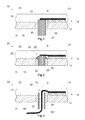
- FIG. 1 a first embodiment of a solar module 10 according to the invention is shown in a sectional view.
- the solar module 10 comprises a solar cell 12, which is arranged in an encapsulation 14.
- the solar module 10 may comprise any number of solar cells.
- the combination of 60 or 72 solar cells into a string consisting of 6 x 10 or 6 x 12 solar cells is frequently encountered.
- the encapsulation 14 comprises a glass sheet 16 having a first glass surface 18 and a second glass surface 20 and a layer 22 of potting material.
- the encapsulation 14 may also comprise a further glass pane 16 or a foil.
- the radiation energy is intended to strike the solar cell 12 by means of rays which pass through the glass pane 16 from the first glass surface 18 to the second glass surface 20. Accordingly, the solar cell 12 is arranged flush with the second glass surface 20 of the glass pane 16, so that the rays must travel as short as possible and thus less loss through the solar module 10 in order to hit the solar cell 12.
- the solar cell 12 may be constructed of any suitable material, for example, amorphous or crystalline silicon.
- an electrical conductor 24 is connected to the solar cell 12, which dissipates the electrical energy generated by it.
- the electrical conductor 24 may for example be designed as a soldering tape.
- the electrical conductor 24 is conductively connected, for example by soldering, to a body 26 ', which is fused into the glass pane 16.
- the body 26 ' is formed substantially cuboid or cylindrical, and has an inner end 28 and an outer end 30 on.
- the geometric shape of the body 26 ' can be chosen arbitrarily.
- the body 26 'passes through the glass sheet 16, so that at an outer end 30 of the body 26' further lines connected may be (not shown) to integrate the solar cell or the solar module 10 in a circuit.
- the electrical energy is derived on the side of the solar module 10, which faces the radiation source, typically the sun.
- the electrical energy is dissipated on the side facing away from the sun.
- the inventive principle is not limited to one side of the solar module 10 and arbitrarily applicable to one or the other or both sides.
- the solar cell 12 is covered on its side facing away from the sun by the layer 22 of encapsulating material.
- the layer 22 of encapsulating material it is just as possible to produce the layer 22 with a thickness that corresponds to that of the solar cell 12, so that it is flush with the solar cell 12. In this case, the solar cell 12 would be surrounded only by the end face of the layer 22 of encapsulating material.
- the body 26 ' projects over the glass sheet 16 on both sides. But it can also be designed so that it is flush on one or both sides with the glass surfaces 18, 20 of the glass sheet 16. In particular, this avoids that the body 26 'in the region of the outer end 30 collides with objects which are located in the vicinity of the solar module 10. Such collisions can lead to a loosening of the body 26 'or to damage of the glass pane 16 and thus of the solar module 10.
- FIG. 2 a second embodiment of the solar module 10 according to the invention is shown.
- the structure is substantially similar to the first embodiment, which in FIG. 1 is described.
- the body 26 " is designed as a bolt with a head 32.
- the head 32 serves as a stop, so that the position of the body 26" with respect to the glass pane 16 during melting can be better determined.
- the outer end 30 terminates flush with the first glass surface 18.
- the electrical conductor 24 is connected at the head 32 to the body 26 ".
- the body 26 '" has a through-bore 34 through which the electrical conductor 24 can be routed, in which case the body 26''need not be made of electrically conductive material, nor does the electrical conductor 24 need to be connected to the Body 26 '"conductively connected.
- FIG. 4 a fourth embodiment of the solar module 10 according to the invention is shown.
- the body 26 "" provided with a thread 38, in which a screw 40 from the first glass surface 18 forth, so from the front of the solar module, on which hit the rays can be screwed.
- the electrical conductor 24 is subdivided into a first section 24 'and a second section 24 ", wherein the first section 24' is arranged in the encapsulation 14 and is connected to the solar cell 12.
- the second section 24" of the electrical conductor 24 can be a Include flat tongue and by means of the screw 40 with the body 26 "" are conductively connected.
- the second portion 24" of the electrical conductor 24 and the electrically conductive connection between the body 26 "" and the second portion 24 "of the electrical conductor 24 from external influences such as snow loads is preferably one further encapsulation 42 is provided. Furthermore, a loosening of the screw 40 during operation of the solar module 10 is prevented.
- the body 26 is arranged in a passage region 36.
- the center of this passage region 36 may coincide with a longitudinal axis A of the body 26.
- the glass pane 16 is heated only in the feedthrough area 36 and the body 26 is guided through the glass pane 16 within this feedthrough area 36.
Landscapes
- Photovoltaic Devices (AREA)
Applications Claiming Priority (1)
| Application Number | Priority Date | Filing Date | Title |
|---|---|---|---|
| DE102010001016A DE102010001016A1 (de) | 2010-01-19 | 2010-01-19 | Anschlusseinheit für Photovoltaische Module |
Publications (1)
| Publication Number | Publication Date |
|---|---|
| EP2346091A2 true EP2346091A2 (fr) | 2011-07-20 |
Family
ID=43971806
Family Applications (1)
| Application Number | Title | Priority Date | Filing Date |
|---|---|---|---|
| EP11151233A Withdrawn EP2346091A2 (fr) | 2010-01-19 | 2011-01-18 | Unité de raccordement pour modules photovoltaïques |
Country Status (5)
| Country | Link |
|---|---|
| US (1) | US20110174375A1 (fr) |
| EP (1) | EP2346091A2 (fr) |
| JP (1) | JP2011155260A (fr) |
| CN (1) | CN102184993A (fr) |
| DE (1) | DE102010001016A1 (fr) |
Families Citing this family (6)
| Publication number | Priority date | Publication date | Assignee | Title |
|---|---|---|---|---|
| DE102010016636B4 (de) * | 2010-04-26 | 2017-03-02 | Calyxo Gmbh | Solarmodul mit verbesserter Verkapselung sowie Anschlusskontaktführung und Verfahren zum Verkapseln von Solarmodulen |
| US8925286B2 (en) | 2011-09-23 | 2015-01-06 | GM Global Technology Operations LLC | Window module with integrated electropolymeric sunshade |
| TWI449191B (zh) * | 2011-09-30 | 2014-08-11 | 太陽能電池封裝結構及電路設計 | |
| US20150020870A1 (en) * | 2012-02-14 | 2015-01-22 | Honda Motor Co., Ltd. | Solar cell module |
| JP5835375B2 (ja) * | 2014-02-27 | 2015-12-24 | トヨタ自動車株式会社 | 太陽電池搭載構造 |
| JP6176492B2 (ja) * | 2014-03-31 | 2017-08-09 | 株式会社Gsユアサ | 放電ランプ及びこの放電ランプを用いた光照射装置 |
Citations (3)
| Publication number | Priority date | Publication date | Assignee | Title |
|---|---|---|---|---|
| DE761322C (de) | 1941-12-07 | 1954-03-15 | Telefunken Gmbh | Herstellen von Glas-Glas-, Glas-Metall- und Glas-Keramik-Verbindungen |
| DE3047399A1 (de) | 1980-12-16 | 1982-07-15 | Licentia Patent-Verwaltungs-Gmbh, 6000 Frankfurt | "verfahren zur mechanischen und elektrischen verbindung gekapselter solarzellen-generatoren mit aeusseren anschlussleitern" |
| DE10225140A1 (de) | 2002-05-29 | 2003-12-11 | Wuerth Solar Gmbh & Co Kg | Solarmodul |
Family Cites Families (5)
| Publication number | Priority date | Publication date | Assignee | Title |
|---|---|---|---|---|
| US3183361A (en) * | 1959-08-07 | 1965-05-11 | Texas Instruments Inc | Method of making glass sealed electric circuit devices and article resulting therefrom |
| GB1554507A (en) * | 1977-04-28 | 1979-10-24 | Tideland Signal Corp | Enclosure for solar cells |
| FR2850489B1 (fr) * | 2003-01-24 | 2005-05-06 | Dgtec | Procede de realisation d'un module photovoltaique et module photovoltaique realise par ce procede |
| US20090114262A1 (en) * | 2006-08-18 | 2009-05-07 | Adriani Paul M | Methods and Devices for Large-Scale Solar Installations |
| CN201181708Y (zh) * | 2008-04-03 | 2009-01-14 | 巨茂光电(厦门)有限公司 | 一种用于点支式玻璃栏杆的光伏组件装置 |
-
2010
- 2010-01-19 DE DE102010001016A patent/DE102010001016A1/de not_active Ceased
-
2011
- 2011-01-17 US US13/007,686 patent/US20110174375A1/en not_active Abandoned
- 2011-01-18 EP EP11151233A patent/EP2346091A2/fr not_active Withdrawn
- 2011-01-19 CN CN2011100304408A patent/CN102184993A/zh active Pending
- 2011-01-19 JP JP2011008530A patent/JP2011155260A/ja active Pending
Patent Citations (3)
| Publication number | Priority date | Publication date | Assignee | Title |
|---|---|---|---|---|
| DE761322C (de) | 1941-12-07 | 1954-03-15 | Telefunken Gmbh | Herstellen von Glas-Glas-, Glas-Metall- und Glas-Keramik-Verbindungen |
| DE3047399A1 (de) | 1980-12-16 | 1982-07-15 | Licentia Patent-Verwaltungs-Gmbh, 6000 Frankfurt | "verfahren zur mechanischen und elektrischen verbindung gekapselter solarzellen-generatoren mit aeusseren anschlussleitern" |
| DE10225140A1 (de) | 2002-05-29 | 2003-12-11 | Wuerth Solar Gmbh & Co Kg | Solarmodul |
Also Published As
| Publication number | Publication date |
|---|---|
| JP2011155260A (ja) | 2011-08-11 |
| CN102184993A (zh) | 2011-09-14 |
| US20110174375A1 (en) | 2011-07-21 |
| DE102010001016A1 (de) | 2011-07-21 |
Similar Documents
| Publication | Publication Date | Title |
|---|---|---|
| DE69833862T2 (de) | Solarzellenmodul | |
| EP2346091A2 (fr) | Unité de raccordement pour modules photovoltaïques | |
| EP2805357B1 (fr) | Produit semi-fini d'une cellule solaire multijonction et procédé de fabrication d'une cellule solaire multijonction | |
| DE102009022125A1 (de) | Isolierglasverbund mit schräg angeordneten Photovoltaik Zellen und Verfahren zur Herstellung und Anwendung | |
| DE102005033272A1 (de) | Konzentrator-Photovoltaik-Einrichtung, daraus gebildetes PV-Konzentratormodul sowie Herstellverfahren hierfür | |
| EP0680100A2 (fr) | Procédé de traitement de plaquettes semi-conductrices minces et cellules solaires en silicum cristallin | |
| DE102009026149A1 (de) | Verbundsystem für Photovoltaik-Module | |
| DE102008006166A1 (de) | Verfahren zur Herstellung eines photovoltaischen Moduls | |
| EP2761670B1 (fr) | Module solaire sans cadre doté de trous de montage et procédé de fabrication d'un tel module | |
| EP2831924A1 (fr) | Module photovoltaïque doté d'un dispositif refroidisseur | |
| WO2024061561A1 (fr) | Module photovoltaïque-thermique | |
| DE202021104477U1 (de) | Photovoltaikmodul | |
| EP3365973B1 (fr) | Élément arrière pour module solaire | |
| DE112009002356T5 (de) | Dünnschicht-Solarzellenreihe | |
| DE102010020974A1 (de) | Verfahren zum Herstellen von Spezialsolarzellen aus einem Wafer | |
| DE102010005970A1 (de) | Verfahren zur Herstellung eines photovoltaischen Dünnschichtmoduls | |
| DE102011055143A1 (de) | Beidseitig kontaktierte Halbleiterwafer-Solarzelle mit oberflächenpassivierter Rückseite | |
| DE102012216740B4 (de) | Silizium-Solarzelle, die durch Zerteilen einer auf einem Silizium-Wafer ausgebildeten Ausgangssolarzelle erzeugt ist, Photovoltaikmodul und Verfahren zur Herstellung einer Solarzelle | |
| DE112012006439T5 (de) | Solarzellenmodul und Verfahren zur Herstellung desselben | |
| WO2014075919A1 (fr) | Module photovoltaïque pourvu d'une tôle de renfort arrière | |
| DE102008046480A1 (de) | Verfahren zur Herstellung einer lötbaren LFC-Solarzellenrückseite und aus derartigen LFC-Solarzellen verschaltetes Solarmodul | |
| DE102014106964A1 (de) | Gebäudebauelement mit Photovoltaikfunktionalität sowie Verfahren zum Herstellen eines Gebäudebauelements mit Photovoltaikfunktionalität | |
| EP2929570A1 (fr) | Module solaire avec boîte de jonction | |
| EP2786422B1 (fr) | Module solaire sans cadre muni d'un support de module | |
| DE112014004490T5 (de) | Solarzellenmodul und Solarzellenmodulfertigungsverfahren |
Legal Events
| Date | Code | Title | Description |
|---|---|---|---|
| PUAI | Public reference made under article 153(3) epc to a published international application that has entered the european phase |
Free format text: ORIGINAL CODE: 0009012 |
|
| 17P | Request for examination filed |
Effective date: 20110118 |
|
| AK | Designated contracting states |
Kind code of ref document: A2 Designated state(s): AL AT BE BG CH CY CZ DE DK EE ES FI FR GB GR HR HU IE IS IT LI LT LU LV MC MK MT NL NO PL PT RO RS SE SI SK SM TR |
|
| AX | Request for extension of the european patent |
Extension state: BA ME |
|
| STAA | Information on the status of an ep patent application or granted ep patent |
Free format text: STATUS: THE APPLICATION HAS BEEN WITHDRAWN |
|
| 18W | Application withdrawn |
Effective date: 20130722 |