EP2346129A2 - Spannsystem zur Verbindung von Drahtgitterkabelkanalabschnitte - Google Patents
Spannsystem zur Verbindung von Drahtgitterkabelkanalabschnitte Download PDFInfo
- Publication number
- EP2346129A2 EP2346129A2 EP11150944A EP11150944A EP2346129A2 EP 2346129 A2 EP2346129 A2 EP 2346129A2 EP 11150944 A EP11150944 A EP 11150944A EP 11150944 A EP11150944 A EP 11150944A EP 2346129 A2 EP2346129 A2 EP 2346129A2
- Authority
- EP
- European Patent Office
- Prior art keywords
- cable channel
- sections
- bars
- relevant
- section
- Prior art date
- Legal status (The legal status is an assumption and is not a legal conclusion. Google has not performed a legal analysis and makes no representation as to the accuracy of the status listed.)
- Granted
Links
- 230000008878 coupling Effects 0.000 description 4
- 238000010168 coupling process Methods 0.000 description 4
- 238000005859 coupling reaction Methods 0.000 description 4
- 230000000295 complement effect Effects 0.000 description 1
- 238000010276 construction Methods 0.000 description 1
- 230000001419 dependent effect Effects 0.000 description 1
- 230000004048 modification Effects 0.000 description 1
- 238000012986 modification Methods 0.000 description 1
Images
Classifications
-
- H—ELECTRICITY
- H02—GENERATION; CONVERSION OR DISTRIBUTION OF ELECTRIC POWER
- H02G—INSTALLATION OF ELECTRIC CABLES OR LINES, OR OF COMBINED OPTICAL AND ELECTRIC CABLES OR LINES
- H02G3/00—Installations of electric cables or lines or protective tubing therefor in or on buildings, equivalent structures or vehicles
- H02G3/02—Details
- H02G3/04—Protective tubing or conduits, e.g. cable ladders or cable troughs
- H02G3/0437—Channels
- H02G3/0443—Channels formed by wire or analogous netting
-
- H—ELECTRICITY
- H02—GENERATION; CONVERSION OR DISTRIBUTION OF ELECTRIC POWER
- H02G—INSTALLATION OF ELECTRIC CABLES OR LINES, OR OF COMBINED OPTICAL AND ELECTRIC CABLES OR LINES
- H02G3/00—Installations of electric cables or lines or protective tubing therefor in or on buildings, equivalent structures or vehicles
- H02G3/02—Details
- H02G3/06—Joints for connecting lengths of protective tubing or channels, to each other or to casings, e.g. to distribution boxes; Ensuring electrical continuity in the joint
- H02G3/0608—Joints for connecting non cylindrical conduits, e.g. channels
Definitions
- the present invention is referred to a Clamping system for connecting wire mesh cable channel sections.
- the invention generally refers to the laying and assembly of wire mesh cable channels, for the laying of wires in all kinds of works and constructions.
- wire mesh cable channels those channels built on the basis of a plurality of sections in the shape of a tray, that are connected one after another.
- Each section of the cable channel is formed by a plurality of metallic wire bars that extend lengthwise and that are joined together by means on U-shaped metallic wire bars transversely positioned and welded to the longitudinal bars, such longitudinal bars forming the side walls and the bottom wall of the channel.
- the European Patent document 0418167 also published as ES 2066167 , discloses a quick-mount clamping device which is used to obtain a cable channel comprising at least two channel sections.
- This clamp is arranged as an elongate rigid strip, whose first end has the shape of an approximately semi-cylindrical longitudinal groove, which has been foreseen to tightly fit into one of the longitudinal bars of the cable channel, and with a second end in the shape of a longitudinal flange extending in a direction opposite to the opening of the groove of the first end - towards the interior of the wire channel - and lugs or tabs that can be bent around a respective vertical section of the U-shaped transversal wire bar; when the lug or tab is bent, with the help of a special tool, it fits into an opening which has been foreseen in the body of the rigid strip.
- the cable duct or channel resulting from the coupling of different sections offers a proper resistance against the pulling and twisting efforts occurring between sections, but shows little resistance against efforts made in a direction perpendicular to the laying direction of the channel, which are caused, for instance, by the weight of the cables, which is inadequate for the consistency of the the channel system.
- the longitudinal tab of the second end of such clamp extends towards the interior of the cable channel, it could cause eventual damages to the cables laid over the channel.
- the European Patent document 0973238 also published as ES 2279589 , describes a wire mesh cable channel consisting of different sections that can be assembled without the need for additional clamping devices, by attaching, in a longitudinal direction, one of the ends of the cable through which includes, at least, two U-shaped wire crossbars attached to the longitudinal wire bars and which are adequately spaced so that it is possible to snap-on a U-shaped wire crossbar present at the opposite side of an adjacent section of cable channel.
- This tight coupling of the complementary ends of the adjacent channel sections provides the resulting channel assembly with an appropriate strength against any force applied in a direction which is perpendicular to the cable laying direction.
- this type of coupling is easily detached when it is subject to twisting forces between the different sections, in such cable laying direction, with the resulting risk that the sections may become uncoupled.
- the object of this patent is to provide a clamping system that allows to connect wire mesh cable channel sections, consisting of a single-piece clamp that guarantees an appropriate resistance against the forces exercised between the different sections of the cable channel obtained, both in a direction that is perpendicular to the cable channel laying direction and against any pulling and twisting efforts made in such channel laying direction.
- the invention is based on a clamping system that allows to attach wire mesh cable channel sections, each cable channel section being formed by a plurality of longitudinal wire bars that form the side walls and the bottom wall of the cable channel and by a plurality of U-shaped wire mesh bars with vertical branches and a horizontal branch, that are welded across the longitudinal bars and evenly spaced along the section, starting on both ends;
- the relevant hook ends are configured to be fitted to the relevant longitudinal bars, in the manner of a clip.
- Another additional advantage, according to yet another characteristic of the invention, is obtained when at least the relevant hook ends of the first clamp section comprise a flange that is used to manually push the hook end against the relevant longitudinal bar, thus making it easier to fit the end to the bar.
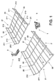
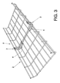
- a cable channel is obtained by attaching, one after another, a plurality of cable channel sections 2, in the shape of a tray, where the cabling is laid, each section 2 being formed by a plurality of longitudinal wire bars 20 that form the side walls and the bottom wall of the cable channel, and by a plurality of U-shaped wire bars 21 that are transversely welded to the longitudinal bars and that have been uniformly spaced along the section, starting on the ends 22, 23 of the cable channel section 2. Additionally, it can be seen that the U-shaped bars 21 comprise two vertical branches 210 and a vertical branch 211.
- the clamping system which has been generally designated by means of the numerical reference 1, comprises a series of clamps 3 with a general shape of an L, that have been arranged to be tightly fitted to the U-shaped wire crossbars 21, especially on the vertical branches 210 and the horizontal branches 211, and additionally, on the longitudinal bars 20 forming the side walls and the bottom wall of the cable channel, as it will be explained in more detail below.
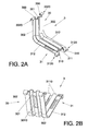
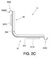
- each clamp 3 comprises a first clamp section 30 and another clamp section 31, the first clamp section being foreseen so that it can be tightly fitted to the vertical branches 210 of the U-shaped wire bars 21 located at the ends of two adjacent sections of the cable channel; and the second clamp section 31 has been foreseen so that it can be tightly fitted to the horizontal branch 211 of the U-shaped wire bars 21 located at the ends of two adjacent sections of the cable channel.
- both the first clamp section 30 and the second clamp section 31 have been foreseen as a piece with the general shape of a W, comprising:
- these flange sections 302, 312 extend in an essentially parallel manner with respect to the diameters of the longitudinal grooves 300, 310.
- said flange sections 302, 312 respectively comprise ends 3020, 3120 with the general shape of a hook, that are used to tightly fit them to the longitudinal bars 20 that form the side wall and the bottom wall, respectively, of the cable channel. Additionally, it can be appreciated that the hook ends 3020 of the first clamp section 30 are opened in the opposite direction to that of the hook ends 3120 of the second clamp section 31. This way, the hook ends 3020, 3120 are coupled to the relevant longitudinal bars, in an up to down or in a down to up direction, respectively, or vice versa, in the opposite case, which has not been represented.
- the relevant hook ends 3020, 3120 are configured to fit as a clip to the respective longitudinal bars 20.
- the relevant hook ends 3020 of the first clamp section 30 comprise a flange 30200, which serves to manually push the hook end against the relevant longitudinal bar 20, thus making it easier to fit such end to the said bar.
- the clamps an be additionally welded to the bar sections of each element of the cable channel, so that this latter one has an appropriate structural strength.
Landscapes
- Engineering & Computer Science (AREA)
- Architecture (AREA)
- Civil Engineering (AREA)
- Structural Engineering (AREA)
- Clamps And Clips (AREA)
- Mutual Connection Of Rods And Tubes (AREA)
- Details Of Indoor Wiring (AREA)
Applications Claiming Priority (1)
| Application Number | Priority Date | Filing Date | Title |
|---|---|---|---|
| ES201030034A ES2388519B1 (es) | 2010-01-15 | 2010-01-15 | Sistema de grapado para unión de tramos de canal para cables de rejilla, mejorado |
Publications (3)
| Publication Number | Publication Date |
|---|---|
| EP2346129A2 true EP2346129A2 (de) | 2011-07-20 |
| EP2346129A3 EP2346129A3 (de) | 2011-10-19 |
| EP2346129B1 EP2346129B1 (de) | 2013-07-17 |
Family
ID=43875335
Family Applications (1)
| Application Number | Title | Priority Date | Filing Date |
|---|---|---|---|
| EP11150944.4A Not-in-force EP2346129B1 (de) | 2010-01-15 | 2011-01-14 | Spannsystem zur Verbindung von Drahtgitterkabelkanalabschnitte |
Country Status (2)
| Country | Link |
|---|---|
| EP (1) | EP2346129B1 (de) |
| ES (1) | ES2388519B1 (de) |
Cited By (2)
| Publication number | Priority date | Publication date | Assignee | Title |
|---|---|---|---|---|
| EP2811595B1 (de) * | 2012-02-02 | 2015-12-16 | Aiscan, S.L. | Verbindungselement für gitterkabelrinnen |
| US11677221B2 (en) | 2020-10-22 | 2023-06-13 | Panduit Corp. | Locking snap-on splice for cable basket |
Families Citing this family (2)
| Publication number | Priority date | Publication date | Assignee | Title |
|---|---|---|---|---|
| EP4080701A1 (de) | 2021-04-20 | 2022-10-26 | Erico International Corporation | Kabelrinnenklammern und verfahren zum verwenden derselben |
| US11962135B2 (en) | 2022-02-11 | 2024-04-16 | Erico International Corporation | Splice clip for cable trays |
Citations (2)
| Publication number | Priority date | Publication date | Assignee | Title |
|---|---|---|---|---|
| EP0418167A1 (de) | 1989-09-15 | 1991-03-20 | Krieg Et Zivy Industries | Schnellverbinder für verlotete Kabelrinne aus Metalldrahtgitter |
| EP0973238A1 (de) | 1998-07-11 | 2000-01-19 | OBO Bettermann GmbH & Co. KG. | Gitterkabelrinne |
Family Cites Families (5)
| Publication number | Priority date | Publication date | Assignee | Title |
|---|---|---|---|---|
| ES2244510T3 (es) * | 2000-05-26 | 2005-12-16 | PAUL HETTICH GMBH & CO. | Elemento de fijacion rapida. |
| ITTO20011096A1 (it) * | 2001-11-23 | 2003-05-23 | Legrand Spa | Organo di giunzione per passerelle portacavi a rete. |
| FR2857792B1 (fr) * | 2003-07-17 | 2010-03-12 | Const Electr De La Seine Ces | Eclisse et support de conduits en treillis comportant au moins deux troncons relies par une telle eclisse |
| EP1793464A1 (de) * | 2005-12-02 | 2007-06-06 | Legrand S.p.A. | Schnellkupplungselement für Gitterkabelkanäle |
| FR2912003B1 (fr) * | 2007-01-31 | 2009-04-17 | Icm Group | Dispositif de fixation pour chemin de cables en fils |
-
2010
- 2010-01-15 ES ES201030034A patent/ES2388519B1/es not_active Expired - Fee Related
-
2011
- 2011-01-14 EP EP11150944.4A patent/EP2346129B1/de not_active Not-in-force
Patent Citations (4)
| Publication number | Priority date | Publication date | Assignee | Title |
|---|---|---|---|---|
| EP0418167A1 (de) | 1989-09-15 | 1991-03-20 | Krieg Et Zivy Industries | Schnellverbinder für verlotete Kabelrinne aus Metalldrahtgitter |
| ES2066167T3 (es) | 1989-09-15 | 1995-03-01 | Krieg & Zivy Ind | Brida rapida para camino de cable en hilos soldados. |
| EP0973238A1 (de) | 1998-07-11 | 2000-01-19 | OBO Bettermann GmbH & Co. KG. | Gitterkabelrinne |
| ES2279589T3 (es) | 1998-07-11 | 2007-08-16 | OBO BETTERMANN GMBH & CO. KG | Canal de cables de rejilla. |
Cited By (2)
| Publication number | Priority date | Publication date | Assignee | Title |
|---|---|---|---|---|
| EP2811595B1 (de) * | 2012-02-02 | 2015-12-16 | Aiscan, S.L. | Verbindungselement für gitterkabelrinnen |
| US11677221B2 (en) | 2020-10-22 | 2023-06-13 | Panduit Corp. | Locking snap-on splice for cable basket |
Also Published As
| Publication number | Publication date |
|---|---|
| EP2346129B1 (de) | 2013-07-17 |
| ES2388519B1 (es) | 2013-12-16 |
| EP2346129A3 (de) | 2011-10-19 |
| ES2388519A1 (es) | 2012-10-16 |
Similar Documents
| Publication | Publication Date | Title |
|---|---|---|
| CA2841709C (en) | Cable tray section | |
| EP2346129B1 (de) | Spannsystem zur Verbindung von Drahtgitterkabelkanalabschnitte | |
| US10578231B2 (en) | Plastic cable management design for retaining wire bundles in aerospace applications | |
| US9958089B2 (en) | Lashing support spacer tie | |
| RU2431911C1 (ru) | Решетчатый желоб, соединение решетчатых желобов и способ изготовления такого решетчатого желоба | |
| KR101245166B1 (ko) | 케이블 트레이 섹션의 연결을 위한 스플라이스 바 | |
| GB2485071A (en) | Coupleable wire mesh cable tray | |
| NL2002610C2 (en) | Quick connect joint for cable trays. | |
| US7097153B2 (en) | Line clamp and method | |
| ES2370570A1 (es) | Sistema de grapado para union de tramos de canal para cables de rejilla. | |
| EP2811595A1 (de) | Verbindungsstück für segmente von korbführungen für kabel | |
| US7175160B2 (en) | Raceway line puller and method of using same | |
| US7201364B2 (en) | Raceway line puller and method | |
| EP2704277B1 (de) | Verbessertes verbindungsstück für segmente von korbführungen für kabel | |
| JP2006158114A (ja) | 上下分割型のフリーアクセス管及びその管路 | |
| CN210273413U (zh) | 一种新型线缆固定装置 | |
| KR20150085331A (ko) | 배선용 전선덕트 | |
| ITTO20001059A1 (it) | Passerella portacavi a rete e relativo organo di protezione. | |
| KR200428606Y1 (ko) | 급전선 일체형 슬림 클램프 | |
| ITPD20130096A1 (it) | Canale portacavi ed elemento di giunzione | |
| KR101268252B1 (ko) | 가공케이블 트레이 | |
| AU2010101522A4 (en) | Cable support and methods of supporting cables | |
| BR102023022480B1 (pt) | Cabo mensageiro | |
| JP3326449B2 (ja) | 配線・配管材の布設用シュータ及び布設用シュータ付受け具並びに配線・配管材の布設方法 | |
| RU172598U1 (ru) | Натяжной зажим |
Legal Events
| Date | Code | Title | Description |
|---|---|---|---|
| PUAI | Public reference made under article 153(3) epc to a published international application that has entered the european phase |
Free format text: ORIGINAL CODE: 0009012 |
|
| AK | Designated contracting states |
Kind code of ref document: A2 Designated state(s): AL AT BE BG CH CY CZ DE DK EE ES FI FR GB GR HR HU IE IS IT LI LT LU LV MC MK MT NL NO PL PT RO RS SE SI SK SM TR |
|
| AX | Request for extension of the european patent |
Extension state: BA ME |
|
| PUAL | Search report despatched |
Free format text: ORIGINAL CODE: 0009013 |
|
| AK | Designated contracting states |
Kind code of ref document: A3 Designated state(s): AL AT BE BG CH CY CZ DE DK EE ES FI FR GB GR HR HU IE IS IT LI LT LU LV MC MK MT NL NO PL PT RO RS SE SI SK SM TR |
|
| AX | Request for extension of the european patent |
Extension state: BA ME |
|
| RIC1 | Information provided on ipc code assigned before grant |
Ipc: H02G 3/04 20060101AFI20110912BHEP Ipc: H02G 3/06 20060101ALI20110912BHEP |
|
| 17P | Request for examination filed |
Effective date: 20120413 |
|
| GRAP | Despatch of communication of intention to grant a patent |
Free format text: ORIGINAL CODE: EPIDOSNIGR1 |
|
| GRAS | Grant fee paid |
Free format text: ORIGINAL CODE: EPIDOSNIGR3 |
|
| GRAA | (expected) grant |
Free format text: ORIGINAL CODE: 0009210 |
|
| AK | Designated contracting states |
Kind code of ref document: B1 Designated state(s): AL AT BE BG CH CY CZ DE DK EE ES FI FR GB GR HR HU IE IS IT LI LT LU LV MC MK MT NL NO PL PT RO RS SE SI SK SM TR |
|
| REG | Reference to a national code |
Ref country code: GB Ref legal event code: FG4D |
|
| REG | Reference to a national code |
Ref country code: CH Ref legal event code: EP |
|
| REG | Reference to a national code |
Ref country code: IE Ref legal event code: FG4D |
|
| REG | Reference to a national code |
Ref country code: AT Ref legal event code: REF Ref document number: 622718 Country of ref document: AT Kind code of ref document: T Effective date: 20130815 |
|
| REG | Reference to a national code |
Ref country code: DE Ref legal event code: R096 Ref document number: 602011002344 Country of ref document: DE Effective date: 20130912 |
|
| REG | Reference to a national code |
Ref country code: AT Ref legal event code: MK05 Ref document number: 622718 Country of ref document: AT Kind code of ref document: T Effective date: 20130717 |
|
| REG | Reference to a national code |
Ref country code: NL Ref legal event code: VDEP Effective date: 20130717 |
|
| REG | Reference to a national code |
Ref country code: LT Ref legal event code: MG4D |
|
| PG25 | Lapsed in a contracting state [announced via postgrant information from national office to epo] |
Ref country code: AT Free format text: LAPSE BECAUSE OF FAILURE TO SUBMIT A TRANSLATION OF THE DESCRIPTION OR TO PAY THE FEE WITHIN THE PRESCRIBED TIME-LIMIT Effective date: 20130717 Ref country code: PT Free format text: LAPSE BECAUSE OF FAILURE TO SUBMIT A TRANSLATION OF THE DESCRIPTION OR TO PAY THE FEE WITHIN THE PRESCRIBED TIME-LIMIT Effective date: 20131118 Ref country code: HR Free format text: LAPSE BECAUSE OF FAILURE TO SUBMIT A TRANSLATION OF THE DESCRIPTION OR TO PAY THE FEE WITHIN THE PRESCRIBED TIME-LIMIT Effective date: 20130717 Ref country code: NO Free format text: LAPSE BECAUSE OF FAILURE TO SUBMIT A TRANSLATION OF THE DESCRIPTION OR TO PAY THE FEE WITHIN THE PRESCRIBED TIME-LIMIT Effective date: 20131017 Ref country code: BE Free format text: LAPSE BECAUSE OF FAILURE TO SUBMIT A TRANSLATION OF THE DESCRIPTION OR TO PAY THE FEE WITHIN THE PRESCRIBED TIME-LIMIT Effective date: 20130717 Ref country code: LT Free format text: LAPSE BECAUSE OF FAILURE TO SUBMIT A TRANSLATION OF THE DESCRIPTION OR TO PAY THE FEE WITHIN THE PRESCRIBED TIME-LIMIT Effective date: 20130717 Ref country code: SE Free format text: LAPSE BECAUSE OF FAILURE TO SUBMIT A TRANSLATION OF THE DESCRIPTION OR TO PAY THE FEE WITHIN THE PRESCRIBED TIME-LIMIT Effective date: 20130717 Ref country code: IS Free format text: LAPSE BECAUSE OF FAILURE TO SUBMIT A TRANSLATION OF THE DESCRIPTION OR TO PAY THE FEE WITHIN THE PRESCRIBED TIME-LIMIT Effective date: 20131117 Ref country code: CY Free format text: LAPSE BECAUSE OF FAILURE TO SUBMIT A TRANSLATION OF THE DESCRIPTION OR TO PAY THE FEE WITHIN THE PRESCRIBED TIME-LIMIT Effective date: 20130626 |
|
| PG25 | Lapsed in a contracting state [announced via postgrant information from national office to epo] |
Ref country code: ES Free format text: LAPSE BECAUSE OF FAILURE TO SUBMIT A TRANSLATION OF THE DESCRIPTION OR TO PAY THE FEE WITHIN THE PRESCRIBED TIME-LIMIT Effective date: 20131028 Ref country code: LV Free format text: LAPSE BECAUSE OF FAILURE TO SUBMIT A TRANSLATION OF THE DESCRIPTION OR TO PAY THE FEE WITHIN THE PRESCRIBED TIME-LIMIT Effective date: 20130717 Ref country code: FI Free format text: LAPSE BECAUSE OF FAILURE TO SUBMIT A TRANSLATION OF THE DESCRIPTION OR TO PAY THE FEE WITHIN THE PRESCRIBED TIME-LIMIT Effective date: 20130717 Ref country code: PL Free format text: LAPSE BECAUSE OF FAILURE TO SUBMIT A TRANSLATION OF THE DESCRIPTION OR TO PAY THE FEE WITHIN THE PRESCRIBED TIME-LIMIT Effective date: 20130717 Ref country code: SI Free format text: LAPSE BECAUSE OF FAILURE TO SUBMIT A TRANSLATION OF THE DESCRIPTION OR TO PAY THE FEE WITHIN THE PRESCRIBED TIME-LIMIT Effective date: 20130717 Ref country code: NL Free format text: LAPSE BECAUSE OF FAILURE TO SUBMIT A TRANSLATION OF THE DESCRIPTION OR TO PAY THE FEE WITHIN THE PRESCRIBED TIME-LIMIT Effective date: 20130717 Ref country code: GR Free format text: LAPSE BECAUSE OF FAILURE TO SUBMIT A TRANSLATION OF THE DESCRIPTION OR TO PAY THE FEE WITHIN THE PRESCRIBED TIME-LIMIT Effective date: 20131018 |
|
| PG25 | Lapsed in a contracting state [announced via postgrant information from national office to epo] |
Ref country code: CY Free format text: LAPSE BECAUSE OF FAILURE TO SUBMIT A TRANSLATION OF THE DESCRIPTION OR TO PAY THE FEE WITHIN THE PRESCRIBED TIME-LIMIT Effective date: 20130717 |
|
| PG25 | Lapsed in a contracting state [announced via postgrant information from national office to epo] |
Ref country code: EE Free format text: LAPSE BECAUSE OF FAILURE TO SUBMIT A TRANSLATION OF THE DESCRIPTION OR TO PAY THE FEE WITHIN THE PRESCRIBED TIME-LIMIT Effective date: 20130717 Ref country code: RO Free format text: LAPSE BECAUSE OF FAILURE TO SUBMIT A TRANSLATION OF THE DESCRIPTION OR TO PAY THE FEE WITHIN THE PRESCRIBED TIME-LIMIT Effective date: 20130717 Ref country code: DK Free format text: LAPSE BECAUSE OF FAILURE TO SUBMIT A TRANSLATION OF THE DESCRIPTION OR TO PAY THE FEE WITHIN THE PRESCRIBED TIME-LIMIT Effective date: 20130717 Ref country code: SK Free format text: LAPSE BECAUSE OF FAILURE TO SUBMIT A TRANSLATION OF THE DESCRIPTION OR TO PAY THE FEE WITHIN THE PRESCRIBED TIME-LIMIT Effective date: 20130717 Ref country code: CZ Free format text: LAPSE BECAUSE OF FAILURE TO SUBMIT A TRANSLATION OF THE DESCRIPTION OR TO PAY THE FEE WITHIN THE PRESCRIBED TIME-LIMIT Effective date: 20130717 |
|
| PLBE | No opposition filed within time limit |
Free format text: ORIGINAL CODE: 0009261 |
|
| STAA | Information on the status of an ep patent application or granted ep patent |
Free format text: STATUS: NO OPPOSITION FILED WITHIN TIME LIMIT |
|
| PG25 | Lapsed in a contracting state [announced via postgrant information from national office to epo] |
Ref country code: IT Free format text: LAPSE BECAUSE OF FAILURE TO SUBMIT A TRANSLATION OF THE DESCRIPTION OR TO PAY THE FEE WITHIN THE PRESCRIBED TIME-LIMIT Effective date: 20130717 |
|
| 26N | No opposition filed |
Effective date: 20140422 |
|
| REG | Reference to a national code |
Ref country code: DE Ref legal event code: R097 Ref document number: 602011002344 Country of ref document: DE Effective date: 20140422 |
|
| REG | Reference to a national code |
Ref country code: DE Ref legal event code: R119 Ref document number: 602011002344 Country of ref document: DE |
|
| PG25 | Lapsed in a contracting state [announced via postgrant information from national office to epo] |
Ref country code: LU Free format text: LAPSE BECAUSE OF FAILURE TO SUBMIT A TRANSLATION OF THE DESCRIPTION OR TO PAY THE FEE WITHIN THE PRESCRIBED TIME-LIMIT Effective date: 20140114 |
|
| REG | Reference to a national code |
Ref country code: CH Ref legal event code: PL |
|
| REG | Reference to a national code |
Ref country code: DE Ref legal event code: R119 Ref document number: 602011002344 Country of ref document: DE Effective date: 20140801 |
|
| PG25 | Lapsed in a contracting state [announced via postgrant information from national office to epo] |
Ref country code: LI Free format text: LAPSE BECAUSE OF NON-PAYMENT OF DUE FEES Effective date: 20140131 Ref country code: DE Free format text: LAPSE BECAUSE OF NON-PAYMENT OF DUE FEES Effective date: 20140801 Ref country code: CH Free format text: LAPSE BECAUSE OF NON-PAYMENT OF DUE FEES Effective date: 20140131 |
|
| REG | Reference to a national code |
Ref country code: FR Ref legal event code: ST Effective date: 20140930 |
|
| REG | Reference to a national code |
Ref country code: IE Ref legal event code: MM4A |
|
| PG25 | Lapsed in a contracting state [announced via postgrant information from national office to epo] |
Ref country code: FR Free format text: LAPSE BECAUSE OF NON-PAYMENT OF DUE FEES Effective date: 20140131 |
|
| PG25 | Lapsed in a contracting state [announced via postgrant information from national office to epo] |
Ref country code: IE Free format text: LAPSE BECAUSE OF NON-PAYMENT OF DUE FEES Effective date: 20140114 |
|
| PG25 | Lapsed in a contracting state [announced via postgrant information from national office to epo] |
Ref country code: MC Free format text: LAPSE BECAUSE OF FAILURE TO SUBMIT A TRANSLATION OF THE DESCRIPTION OR TO PAY THE FEE WITHIN THE PRESCRIBED TIME-LIMIT Effective date: 20130717 |
|
| GBPC | Gb: european patent ceased through non-payment of renewal fee |
Effective date: 20150114 |
|
| PG25 | Lapsed in a contracting state [announced via postgrant information from national office to epo] |
Ref country code: GB Free format text: LAPSE BECAUSE OF NON-PAYMENT OF DUE FEES Effective date: 20150114 |
|
| PG25 | Lapsed in a contracting state [announced via postgrant information from national office to epo] |
Ref country code: MT Free format text: LAPSE BECAUSE OF FAILURE TO SUBMIT A TRANSLATION OF THE DESCRIPTION OR TO PAY THE FEE WITHIN THE PRESCRIBED TIME-LIMIT Effective date: 20130717 |
|
| PG25 | Lapsed in a contracting state [announced via postgrant information from national office to epo] |
Ref country code: SM Free format text: LAPSE BECAUSE OF FAILURE TO SUBMIT A TRANSLATION OF THE DESCRIPTION OR TO PAY THE FEE WITHIN THE PRESCRIBED TIME-LIMIT Effective date: 20130717 |
|
| PG25 | Lapsed in a contracting state [announced via postgrant information from national office to epo] |
Ref country code: BG Free format text: LAPSE BECAUSE OF FAILURE TO SUBMIT A TRANSLATION OF THE DESCRIPTION OR TO PAY THE FEE WITHIN THE PRESCRIBED TIME-LIMIT Effective date: 20130717 Ref country code: RS Free format text: LAPSE BECAUSE OF FAILURE TO SUBMIT A TRANSLATION OF THE DESCRIPTION OR TO PAY THE FEE WITHIN THE PRESCRIBED TIME-LIMIT Effective date: 20130717 |
|
| PG25 | Lapsed in a contracting state [announced via postgrant information from national office to epo] |
Ref country code: TR Free format text: LAPSE BECAUSE OF FAILURE TO SUBMIT A TRANSLATION OF THE DESCRIPTION OR TO PAY THE FEE WITHIN THE PRESCRIBED TIME-LIMIT Effective date: 20130717 Ref country code: HU Free format text: LAPSE BECAUSE OF FAILURE TO SUBMIT A TRANSLATION OF THE DESCRIPTION OR TO PAY THE FEE WITHIN THE PRESCRIBED TIME-LIMIT; INVALID AB INITIO Effective date: 20110114 |
|
| PG25 | Lapsed in a contracting state [announced via postgrant information from national office to epo] |
Ref country code: MK Free format text: LAPSE BECAUSE OF FAILURE TO SUBMIT A TRANSLATION OF THE DESCRIPTION OR TO PAY THE FEE WITHIN THE PRESCRIBED TIME-LIMIT Effective date: 20130717 |
|
| PG25 | Lapsed in a contracting state [announced via postgrant information from national office to epo] |
Ref country code: AL Free format text: LAPSE BECAUSE OF FAILURE TO SUBMIT A TRANSLATION OF THE DESCRIPTION OR TO PAY THE FEE WITHIN THE PRESCRIBED TIME-LIMIT Effective date: 20130717 |