EP2347848A1 - Procédé de traitement par serrage et machine-outil associée, notamment machine à chanfreiner - Google Patents
Procédé de traitement par serrage et machine-outil associée, notamment machine à chanfreiner Download PDFInfo
- Publication number
- EP2347848A1 EP2347848A1 EP11156774A EP11156774A EP2347848A1 EP 2347848 A1 EP2347848 A1 EP 2347848A1 EP 11156774 A EP11156774 A EP 11156774A EP 11156774 A EP11156774 A EP 11156774A EP 2347848 A1 EP2347848 A1 EP 2347848A1
- Authority
- EP
- European Patent Office
- Prior art keywords
- spindle
- tool
- workpiece
- carrier
- working position
- Prior art date
- Legal status (The legal status is an assumption and is not a legal conclusion. Google has not performed a legal analysis and makes no representation as to the accuracy of the status listed.)
- Granted
Links
- 238000000034 method Methods 0.000 title claims abstract description 11
- 238000003754 machining Methods 0.000 title claims abstract description 6
- 238000005520 cutting process Methods 0.000 claims abstract description 8
- 239000007787 solid Substances 0.000 claims abstract description 5
- 238000006073 displacement reaction Methods 0.000 claims description 7
- 230000000712 assembly Effects 0.000 description 4
- 238000000429 assembly Methods 0.000 description 4
- 230000001360 synchronised effect Effects 0.000 description 4
- 238000012545 processing Methods 0.000 description 3
- 238000004364 calculation method Methods 0.000 description 2
- 239000000969 carrier Substances 0.000 description 2
- 238000010276 construction Methods 0.000 description 2
- 238000011161 development Methods 0.000 description 2
- 241001416181 Axis axis Species 0.000 description 1
- 238000013459 approach Methods 0.000 description 1
- 238000006243 chemical reaction Methods 0.000 description 1
- 238000012937 correction Methods 0.000 description 1
- 238000004519 manufacturing process Methods 0.000 description 1
- 238000004088 simulation Methods 0.000 description 1
Images



Classifications
-
- B—PERFORMING OPERATIONS; TRANSPORTING
- B23—MACHINE TOOLS; METAL-WORKING NOT OTHERWISE PROVIDED FOR
- B23Q—DETAILS, COMPONENTS, OR ACCESSORIES FOR MACHINE TOOLS, e.g. ARRANGEMENTS FOR COPYING OR CONTROLLING; MACHINE TOOLS IN GENERAL CHARACTERISED BY THE CONSTRUCTION OF PARTICULAR DETAILS OR COMPONENTS; COMBINATIONS OR ASSOCIATIONS OF METAL-WORKING MACHINES, NOT DIRECTED TO A PARTICULAR RESULT
- B23Q5/00—Driving or feeding mechanisms; Control arrangements therefor
- B23Q5/22—Feeding members carrying tools or work
- B23Q5/34—Feeding other members supporting tools or work, e.g. saddles, tool-slides, through mechanical transmission
- B23Q5/38—Feeding other members supporting tools or work, e.g. saddles, tool-slides, through mechanical transmission feeding continuously
- B23Q5/40—Feeding other members supporting tools or work, e.g. saddles, tool-slides, through mechanical transmission feeding continuously by feed shaft, e.g. lead screw
-
- B—PERFORMING OPERATIONS; TRANSPORTING
- B23—MACHINE TOOLS; METAL-WORKING NOT OTHERWISE PROVIDED FOR
- B23F—MAKING GEARS OR TOOTHED RACKS
- B23F19/00—Finishing gear teeth by other tools than those used for manufacturing gear teeth
- B23F19/10—Chamfering the end edges of gear teeth
- B23F19/102—Chamfering the end edges of gear teeth by milling
- B23F19/107—Chamfering the end edges of gear teeth by milling the tool being a fly cutter
-
- B—PERFORMING OPERATIONS; TRANSPORTING
- B23—MACHINE TOOLS; METAL-WORKING NOT OTHERWISE PROVIDED FOR
- B23Q—DETAILS, COMPONENTS, OR ACCESSORIES FOR MACHINE TOOLS, e.g. ARRANGEMENTS FOR COPYING OR CONTROLLING; MACHINE TOOLS IN GENERAL CHARACTERISED BY THE CONSTRUCTION OF PARTICULAR DETAILS OR COMPONENTS; COMBINATIONS OR ASSOCIATIONS OF METAL-WORKING MACHINES, NOT DIRECTED TO A PARTICULAR RESULT
- B23Q1/00—Members which are comprised in the general build-up of a form of machine, particularly relatively large fixed members
- B23Q1/25—Movable or adjustable work or tool supports
- B23Q1/44—Movable or adjustable work or tool supports using particular mechanisms
-
- B—PERFORMING OPERATIONS; TRANSPORTING
- B23—MACHINE TOOLS; METAL-WORKING NOT OTHERWISE PROVIDED FOR
- B23Q—DETAILS, COMPONENTS, OR ACCESSORIES FOR MACHINE TOOLS, e.g. ARRANGEMENTS FOR COPYING OR CONTROLLING; MACHINE TOOLS IN GENERAL CHARACTERISED BY THE CONSTRUCTION OF PARTICULAR DETAILS OR COMPONENTS; COMBINATIONS OR ASSOCIATIONS OF METAL-WORKING MACHINES, NOT DIRECTED TO A PARTICULAR RESULT
- B23Q1/00—Members which are comprised in the general build-up of a form of machine, particularly relatively large fixed members
- B23Q1/25—Movable or adjustable work or tool supports
- B23Q1/44—Movable or adjustable work or tool supports using particular mechanisms
- B23Q1/48—Movable or adjustable work or tool supports using particular mechanisms with sliding pairs and rotating pairs
- B23Q1/4828—Movable or adjustable work or tool supports using particular mechanisms with sliding pairs and rotating pairs a single rotating pair followed parallelly by a single sliding pair
Definitions
- the invention relates to a machining method of a workpiece according to the preamble of claim 1 and a machine tool according to the preamble of claim 6.
- a machine tool in which the workpiece is driven by an electric rotary drive.
- the tool is also driven by an electric rotary drive.
- two linear drives are provided for positioning the electric rotary drive of the tool spindle.
- the DE-AS 10 48 762 shows a machine tool with two tool assemblies, each tool assembly is pivotable about its associated pivot axis. The pan must be done by hand here.
- a tooth edge processing machine in which the tool and the workpiece are displaceable against each other with eleven degrees of freedom. Again, to pivot and tilt the rotary actuators are provided.
- the EP 0 107 826 describes a machine tool in which the tool assemblies can change their pivotal position relative to the workpiece spindle. This must be done manually here.
- the pivoting movements that perform the tool spindle or one or more of them carrying carrier are driven by linear drives.
- the machine parts which are to be pivoted relative to one another form lever arms, between which extend the linear drives.
- the procedure according to the invention is that the lengths of the lever arms are the same, so that the linear drive can attack there without torque.
- the conversion then consists essentially only in the set values for the new Enter workpiece. Since the axes can reproducibly approach the various working positions assigned to each workpiece, manual corrections, if any, are required only to a very limited extent.
- the construction of the machine tool according to the invention also makes it possible to use setting data obtained in simulation calculations for the spatial position and the spatial direction of the workpiece spindle. These setting data are input to the electronic control device. Based on the geometric data stored in the electronic processing unit, this then calculates the setting values for the linear drives.
- the linear drive for example, designed as a spindle, wherein either the spindle nut or the threaded spindle is rotationally driven, is not mechanically braked in the working position of the rotary drive for either the spindle nut or the threaded spindle, but held electronically in a defined rotational position.
- the adjustment values for the individual linear drives are preferably stretching. These routes are calculated by an electronic processing unit of the electronic control unit. The starting point for the calculation are characteristic data entered by the operator for the surface to be processed, for example the position of the surface to be processed in space, in particular with respect to a reference system defined by the workpiece axis.
- the working position of the cutting edge of the tool is calculated, ie its spatial position and the associated angles which define the spatial direction of the tool spindle.
- the distances to which the linear drives are set With the length dimensions known from the construction of the machine can then be calculated the distances to which the linear drives are set.
- the use of distances as setting values in combination with the use of linear drives makes it possible to bring the tool spindle into the previously calculated spatial position. It is advantageous if at least the positioning of the tool spindle takes place in the two spatial angles defining the spatial direction by means of spindle drives.
- the device has a tool carrier tower, which is linearly displaceable at least in one spatial direction.
- the tool carrier tower can be swiveled about an axis perpendicular to it.
- a tool spindle carrier carried by the tool carrier tower can be displaced linearly in the direction of the tool carrier axis.
- the tool spindle carrier can be pivoted about a tilt axis lying transverse to the tool carrier tower axis.
- the tool spindle can be arranged linearly displaceable on the tool spindle carrier along its axis.
- the linear displacements of tool carrier tower and tool spindle carrier can also be realized by spindle drives. Again, the rotational position of the spindle or the spindle nut is held in the working position by means of regulation.
- the electronic computing unit Even if the specifications entered by the operator into the machine contain angle data, the electronic computing unit nevertheless calculates distances from it, which are given as setting values to the linear drives.
- the linear actuators are therefore associated with Weggeber to make the adjustment can.
- the drive motors or drive reduction gear have rotary encoders, so that the route length can be determined even with the rotation angles given there.
- each linear unit carries a positionable along its direction of extension slide, wherein the one Carriage the first pivot point and the other carriage is associated with the second pivot point and the second pivot point is connected via a linear - in particular slide guide with the tool assembly.
- the linear drives threaded spindles form, which are driven by individual electrical drives and the spindle nuts are associated with the spindle slide.
- the tool spindle can be displaced linearly along its axial direction on a carrier pivotally mounted around the first bearing point and assigned to the tool arrangement.
- the linear drives are arranged on a rotatable about an axis parallel to its axis axis tower.
- the tower can also be rotatable by means of a linear drive, for example a spindle drive.
- the tower can be displaceable in a direction transverse to the workpiece axis direction and transversely to the spindle extension direction via a spindle drive relative to the machine bed.
- the spindle drives are preferably ball and socket spindle drives with preloaded bearings. This results in backlash.
- a tool spindle can be displaced by synchronous operation of all spindle drives in space.
- the device can be rotated by one of the two pivot points by actuations of only one spindle drive, the tool assembly.
- the workpiece spindle or the tool arrangement can be pivoted about a virtual pivot point by simultaneous actuation of both spindles with different rotational speeds.
- the virtual fulcrum can be the point of attack of the turned from the tool spindle flywheel on a gear.
- the machine tool has two symmetrically arranged towers, each having two spindles and one each sitting on the two spindles tool assemblies.
- the machine tool is used to generate inclines at the end faces of gears 2.
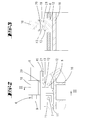
- a gear 2 is held by a chuck of a workpiece spindle 1.
- the workpiece spindle which rotates about the axis W, extends in the Z-axis and is driven by a drive motor 3.
- the inclinations of the end faces of the gears 2 takes place by synchronous machining by means of impact knives 9.
- There are two flywheel blades 9 are provided, which are each arranged on a workpiece spindle 6. On the workpiece spindle 6 but also multi-tooth impact can be arranged.
- Each of the two Tool spindles 6 is assigned to a tool assembly 4.
- the tool assembly 4 has a headstock 18 and a drive motor 5.
- the drive motors 5 of the two tool assemblies 4 are synchronized with the drive motor 3 of the workpiece spindle 1. They are in a fixed speed ratio to each other.
- the machine bed 31 of the machine tool forms a horizontal guide 32.
- a base plate 30 in the direction X is displaced.
- the spindle nut below the base plate 30 is the spindle nut, so that by actuation of the spindle drive 33, the base plate 30 can be displaced in the direction Y.
- a gate-shaped body 23 Fixedly connected to the base plate 30 is a gate-shaped body 23.
- This gate 23 supports a boom 29 which is pivotable about a pivot bearing 26.
- the free end of the boom 29 carries a spindle drive 28, the spindle 10 engages an arm 24 of a tower 16.
- the arm 24 of the tower 16 carries a pivot bearing 25, which forms the spindle nut for the spindle 10.
- the tower 16 is pivotable about a pivot bearing 27 which extends in the X direction. By operating the spindle drive 28, the tower 16 can be rotated about the axis of rotation extending in the X-axis, which is defined by the pivot bearing 27. In this case, the tower 16 is supported by the base plate 30.
- the tower 16 carries two mutually parallel ball roller spindles 7, 8. These two threaded spindles 7, 8 extend in the Y direction. On the head of the tower 16 are the two individual electrical drives 14, 15 for the two spaced apart with a distance A ball roller spindles 7, 8th
- Each of the two ball-roller spindles 7, 8 carries a spindle slide 11, 12.
- Each spindle slide 11, 12 is additionally guided on a guide rail of the tower 16. By turning the threaded spindles 7, 8, the associated spindle slide can be displaced in the Y direction.
- the spindle carriage 11 is assigned a first pivot bearing P1, which is arranged on the tool side of a tool arrangement 4.
- the ball screw spindle 8 associated spindle slide 12 carries a second pivot bearing P2, which is associated with the drive side of the tool assembly 4.
- a support 19 is pivotally mounted about the pivot bearing P1 on the spindle carriage 11. On a double guide 21 of the support 19 is seated a slide guide 13 which is associated with the spindle slide 12.
- This slide guide 13 is pivotable about the second bearing point P2.
- the second bearing point P2 can move away relative to the first bearing point P1.
- the carrier 19 has not only on its underside guides 21, but also on its upper side guides 20. Both guides 21, 20 are parallel to each other and in the extension direction of the carrier 19.
- On the top side guide 20 of the spindle box 18 sits a tool assembly 4 such that the tool 9 can be displaced along its axis of rotation U. This displacement also takes place by means of a linear drive in the form of a ball-and-roller spindle arrangement.
- the tool 9 sits replaceably in a chuck of the tool spindle. 6
- the machine tool has two folding-symmetrically arranged tool arrangements 4, which are each associated with a tower 16, on. It should be emphasized that in the embodiment all rotary actuators are realized via linear drives.
- the linear drives are free of play by a corresponding tension of the bearings, in particular ball bearings.
- the linear drives are provided with linear encoders.
- the respective first bearing points P1 have rotary encoders 22. With the arrangement described, a positioning of the tool arrangement 4 about each virtual space rotation axis is possible.
- the workpiece spindle 1 can also be displaced in its axial direction W for the purpose of delivery or feed.
- the displacement of the tool spindle 6 relative to the carrier 19 can also be done for the purpose of advancing or for the purpose of delivery.
- the machine tool described is able to process various workpieces.
- these workpieces are toothed workpieces, in particular gears.
- In the tooth flanks of these gears should be milled in a corresponding division circumferentially similar surfaces.
- the device is in particular able to quickly change over to the machining of a differently shaped workpiece.
- the tool spindle must be moved to a different working position to the workpiece. This means that the cutting edge of the tool must be brought into another position defined by the three spatial directions X, Y, Z and pivoted into another spatial direction defined by the two solid angles ⁇ and ⁇ .
- the geometrical parameters determining this position have been previously calculated.
- the spatial position of the tool spindle defining coordinates X, Y, Z, ⁇ , ⁇ set values for the total of fourteen linear axes are calculated. This is done taking into account the structural length dimensions of the machine.
- the setting values given by an electronic control device to the linear drives are track dimensions. Do the pro Tool spindle reaches five setting axes of its end position, the working position is approached. In this position, the linear drives are not frictionally clamped or held positively, but fixed by constant readjustment.
- the device according to the invention preferably has two, substantially mirror-symmetrically arranged tool spindles. Each of these spindles associated cutting edit one associated with them surface, the two surfaces are like a roof to each other.
Landscapes
- Engineering & Computer Science (AREA)
- Mechanical Engineering (AREA)
- Machine Tool Units (AREA)
- Milling Processes (AREA)
- Turning (AREA)
Applications Claiming Priority (4)
| Application Number | Priority Date | Filing Date | Title |
|---|---|---|---|
| DE10347149 | 2003-10-10 | ||
| DE10354395A DE10354395A1 (de) | 2003-10-10 | 2003-11-20 | Werkzeugmaschine, insbesondere Abdachmaschine |
| PCT/EP2004/052242 WO2005037477A1 (fr) | 2003-10-10 | 2004-09-20 | Machine-outil a systeme d'usinage par inclinaison |
| EP04766825A EP1677937B1 (fr) | 2003-10-10 | 2004-09-20 | Machine-outil a systeme d'usinage par inclinaison |
Related Parent Applications (2)
| Application Number | Title | Priority Date | Filing Date |
|---|---|---|---|
| EP04766825.6 Division | 2004-09-20 | ||
| EP04766825A Division EP1677937B1 (fr) | 2003-10-10 | 2004-09-20 | Machine-outil a systeme d'usinage par inclinaison |
Publications (2)
| Publication Number | Publication Date |
|---|---|
| EP2347848A1 true EP2347848A1 (fr) | 2011-07-27 |
| EP2347848B1 EP2347848B1 (fr) | 2020-05-13 |
Family
ID=34441865
Family Applications (1)
| Application Number | Title | Priority Date | Filing Date |
|---|---|---|---|
| EP11156774.9A Expired - Lifetime EP2347848B1 (fr) | 2003-10-10 | 2004-09-20 | Procédé de traitement par serrage et machine-outil associée, notamment machine à chanfreiner |
Country Status (3)
| Country | Link |
|---|---|
| EP (1) | EP2347848B1 (fr) |
| AT (1) | ATE524264T1 (fr) |
| DE (1) | DE10354395A1 (fr) |
Cited By (2)
| Publication number | Priority date | Publication date | Assignee | Title |
|---|---|---|---|---|
| CN112517724A (zh) * | 2020-11-28 | 2021-03-19 | 武汉重型机床集团有限公司 | 一种加工范围可调旋轮座 |
| CN118848674A (zh) * | 2024-09-29 | 2024-10-29 | 山东华云机电科技有限公司 | 一种同步加工装置、机加工设备及机加工工艺 |
Families Citing this family (4)
| Publication number | Priority date | Publication date | Assignee | Title |
|---|---|---|---|---|
| DE102008060297B3 (de) * | 2008-12-03 | 2010-07-15 | Boehringer Werkzeugmaschinen Gmbh | Drehmaschine |
| DE102010041481A1 (de) * | 2010-09-27 | 2012-05-10 | Mag Ias Gmbh | Werkzeugmaschine zur Herstellung von Zahnrädern |
| HUE033857T2 (en) * | 2012-11-05 | 2018-01-29 | Telerobot S P A | Industrial automation tool |
| DE202019002667U1 (de) * | 2019-06-25 | 2020-11-11 | Isel Marketing & Sales Gmbh & Co. Kg | Linearführungseinheit |
Citations (4)
| Publication number | Priority date | Publication date | Assignee | Title |
|---|---|---|---|---|
| DE1048762B (de) | 1955-05-16 | 1959-01-15 | Wilhelm Grupp O H G | Verfahren und Maschine zur spanabhebenden Bearbeitung von Stirnkanten an Zahnraedern oder anderen Werkstuecken mit achsparallelen Zaehnen |
| EP0107826A2 (fr) | 1982-10-29 | 1984-05-09 | Wera-Werk Hermann Werner GmbH & Co. | Machine-outil pour le fraisage simultané de plusieurs surfaces des extrémités libres d'une pièce |
| DE19800034A1 (de) * | 1998-01-02 | 1999-07-15 | Elb Schliff Werkzeugmaschinen | Werkzeugmaschine für Bearbeitungswerkzeuge aus der Gruppe Schleifkörper und Fräser mit mindestens einem Werkzeugträger |
| DE10113653A1 (de) | 2001-03-21 | 2002-09-26 | Werner Hermann Wera Werke | Werkzeugmaschinen insbesondere Abdachmaschine |
-
2003
- 2003-11-20 DE DE10354395A patent/DE10354395A1/de not_active Ceased
-
2004
- 2004-09-20 EP EP11156774.9A patent/EP2347848B1/fr not_active Expired - Lifetime
- 2004-09-20 AT AT04766825T patent/ATE524264T1/de active
Patent Citations (4)
| Publication number | Priority date | Publication date | Assignee | Title |
|---|---|---|---|---|
| DE1048762B (de) | 1955-05-16 | 1959-01-15 | Wilhelm Grupp O H G | Verfahren und Maschine zur spanabhebenden Bearbeitung von Stirnkanten an Zahnraedern oder anderen Werkstuecken mit achsparallelen Zaehnen |
| EP0107826A2 (fr) | 1982-10-29 | 1984-05-09 | Wera-Werk Hermann Werner GmbH & Co. | Machine-outil pour le fraisage simultané de plusieurs surfaces des extrémités libres d'une pièce |
| DE19800034A1 (de) * | 1998-01-02 | 1999-07-15 | Elb Schliff Werkzeugmaschinen | Werkzeugmaschine für Bearbeitungswerkzeuge aus der Gruppe Schleifkörper und Fräser mit mindestens einem Werkzeugträger |
| DE10113653A1 (de) | 2001-03-21 | 2002-09-26 | Werner Hermann Wera Werke | Werkzeugmaschinen insbesondere Abdachmaschine |
Cited By (2)
| Publication number | Priority date | Publication date | Assignee | Title |
|---|---|---|---|---|
| CN112517724A (zh) * | 2020-11-28 | 2021-03-19 | 武汉重型机床集团有限公司 | 一种加工范围可调旋轮座 |
| CN118848674A (zh) * | 2024-09-29 | 2024-10-29 | 山东华云机电科技有限公司 | 一种同步加工装置、机加工设备及机加工工艺 |
Also Published As
| Publication number | Publication date |
|---|---|
| DE10354395A1 (de) | 2005-05-19 |
| EP2347848B1 (fr) | 2020-05-13 |
| ATE524264T1 (de) | 2011-09-15 |
Similar Documents
| Publication | Publication Date | Title |
|---|---|---|
| EP2732895B1 (fr) | Machine-outil pour la fabrication de profilés | |
| DE10256222B4 (de) | Maschine und Verfahren mit 7 Achsen zum CNC-gesteuerten spanabhebenden Bearbeiten, insbesondere Wälzfräsen oder Wälzschleifen, von Spiralkegelrädern | |
| EP2247405A2 (fr) | Dispositif de fixation pour une machine d'usinage par enlèvement de copeaux pilotée par ordinateur | |
| EP3778118B1 (fr) | Machine-outil pourvue de deux broches de travail | |
| EP3681670A1 (fr) | Dispositif pour l'orientation et le positionnement d'une pièce par rapport à un faisceau laser d'une machine d'usinage au laser | |
| EP1864739A1 (fr) | Dispositif et procédé d'usinage avant traitement de roues coniques | |
| DE102018118031A1 (de) | Bearbeitungsvorrichtung und Verfahren zur Bearbeitung | |
| DE3750688T2 (de) | Werkzeugmaschine. | |
| EP1025953B1 (fr) | Machine-outil | |
| DE4411255A1 (de) | Sägemaschine für Gehrungs- und Schifterschnitte I | |
| EP1677937B1 (fr) | Machine-outil a systeme d'usinage par inclinaison | |
| EP2347848B1 (fr) | Procédé de traitement par serrage et machine-outil associée, notamment machine à chanfreiner | |
| EP3887091B1 (fr) | Machine-outil avec un premier et un deuxieme support de pieces | |
| EP0787560A1 (fr) | Dispositif d'usinage des barres, des profilés et similaire | |
| WO2007016910A2 (fr) | Procede et dispositif pour usiner des surfaces de pieces | |
| DE4427010C1 (de) | Maschine zum Bearbeiten der Verzahnung von Kegelrädern | |
| WO2002076663A1 (fr) | Machine-outil, notamment machine a chanfreiner les dentures | |
| DE102004006351B4 (de) | Werkzeugmaschine zur spanenden Bearbeitung jeweils eines Werkstückes | |
| DE102016109036A1 (de) | Werkzeugschwenkaggregat für eine Drehmaschine | |
| DD255296A1 (de) | Verzahnmaschine mit cnc-steuerung zur herstellung von kegelraedern | |
| DE102011050498B4 (de) | Werkzeugmaschine zur Stirnkantenabdachung von Zahnrädern | |
| DE19920099B4 (de) | Positioniervorrichtung für Sägeblätter | |
| DE3520521A1 (de) | Maschine zum spanenden einarbeiten der spanraumnuten von laenglichen, am umfang schneidenden werkzeugen mit halbkugelfoermigem ende | |
| DE3933863A1 (de) | Schleifmaschine | |
| DE3936699C2 (de) | Aufsatzgerät für eine Werkzeug-Schleifmaschine |
Legal Events
| Date | Code | Title | Description |
|---|---|---|---|
| PUAI | Public reference made under article 153(3) epc to a published international application that has entered the european phase |
Free format text: ORIGINAL CODE: 0009012 |
|
| AC | Divisional application: reference to earlier application |
Ref document number: 1677937 Country of ref document: EP Kind code of ref document: P |
|
| AK | Designated contracting states |
Kind code of ref document: A1 Designated state(s): AT BE BG CH CY CZ DE DK EE ES FI FR GB GR HU IE IT LI LU MC NL PL PT RO SE SI SK TR |
|
| 17P | Request for examination filed |
Effective date: 20120118 |
|
| STAA | Information on the status of an ep patent application or granted ep patent |
Free format text: STATUS: EXAMINATION IS IN PROGRESS |
|
| 17Q | First examination report despatched |
Effective date: 20170127 |
|
| RAP1 | Party data changed (applicant data changed or rights of an application transferred) |
Owner name: PROFILATOR GMBH & CO. KG |
|
| GRAP | Despatch of communication of intention to grant a patent |
Free format text: ORIGINAL CODE: EPIDOSNIGR1 |
|
| STAA | Information on the status of an ep patent application or granted ep patent |
Free format text: STATUS: GRANT OF PATENT IS INTENDED |
|
| INTG | Intention to grant announced |
Effective date: 20191212 |
|
| GRAS | Grant fee paid |
Free format text: ORIGINAL CODE: EPIDOSNIGR3 |
|
| GRAA | (expected) grant |
Free format text: ORIGINAL CODE: 0009210 |
|
| STAA | Information on the status of an ep patent application or granted ep patent |
Free format text: STATUS: THE PATENT HAS BEEN GRANTED |
|
| AC | Divisional application: reference to earlier application |
Ref document number: 1677937 Country of ref document: EP Kind code of ref document: P |
|
| AK | Designated contracting states |
Kind code of ref document: B1 Designated state(s): AT BE BG CH CY CZ DE DK EE ES FI FR GB GR HU IE IT LI LU MC NL PL PT RO SE SI SK TR |
|
| REG | Reference to a national code |
Ref country code: GB Ref legal event code: FG4D Free format text: NOT ENGLISH |
|
| REG | Reference to a national code |
Ref country code: CH Ref legal event code: EP |
|
| REG | Reference to a national code |
Ref country code: DE Ref legal event code: R096 Ref document number: 502004015861 Country of ref document: DE |
|
| REG | Reference to a national code |
Ref country code: AT Ref legal event code: REF Ref document number: 1269613 Country of ref document: AT Kind code of ref document: T Effective date: 20200615 |
|
| REG | Reference to a national code |
Ref country code: NL Ref legal event code: MP Effective date: 20200513 |
|
| PG25 | Lapsed in a contracting state [announced via postgrant information from national office to epo] |
Ref country code: GR Free format text: LAPSE BECAUSE OF FAILURE TO SUBMIT A TRANSLATION OF THE DESCRIPTION OR TO PAY THE FEE WITHIN THE PRESCRIBED TIME-LIMIT Effective date: 20200814 Ref country code: FI Free format text: LAPSE BECAUSE OF FAILURE TO SUBMIT A TRANSLATION OF THE DESCRIPTION OR TO PAY THE FEE WITHIN THE PRESCRIBED TIME-LIMIT Effective date: 20200513 Ref country code: SE Free format text: LAPSE BECAUSE OF FAILURE TO SUBMIT A TRANSLATION OF THE DESCRIPTION OR TO PAY THE FEE WITHIN THE PRESCRIBED TIME-LIMIT Effective date: 20200513 Ref country code: PT Free format text: LAPSE BECAUSE OF FAILURE TO SUBMIT A TRANSLATION OF THE DESCRIPTION OR TO PAY THE FEE WITHIN THE PRESCRIBED TIME-LIMIT Effective date: 20200914 |
|
| PG25 | Lapsed in a contracting state [announced via postgrant information from national office to epo] |
Ref country code: BG Free format text: LAPSE BECAUSE OF FAILURE TO SUBMIT A TRANSLATION OF THE DESCRIPTION OR TO PAY THE FEE WITHIN THE PRESCRIBED TIME-LIMIT Effective date: 20200813 |
|
| PG25 | Lapsed in a contracting state [announced via postgrant information from national office to epo] |
Ref country code: NL Free format text: LAPSE BECAUSE OF FAILURE TO SUBMIT A TRANSLATION OF THE DESCRIPTION OR TO PAY THE FEE WITHIN THE PRESCRIBED TIME-LIMIT Effective date: 20200513 |
|
| PG25 | Lapsed in a contracting state [announced via postgrant information from national office to epo] |
Ref country code: ES Free format text: LAPSE BECAUSE OF FAILURE TO SUBMIT A TRANSLATION OF THE DESCRIPTION OR TO PAY THE FEE WITHIN THE PRESCRIBED TIME-LIMIT Effective date: 20200513 Ref country code: DK Free format text: LAPSE BECAUSE OF FAILURE TO SUBMIT A TRANSLATION OF THE DESCRIPTION OR TO PAY THE FEE WITHIN THE PRESCRIBED TIME-LIMIT Effective date: 20200513 Ref country code: CZ Free format text: LAPSE BECAUSE OF FAILURE TO SUBMIT A TRANSLATION OF THE DESCRIPTION OR TO PAY THE FEE WITHIN THE PRESCRIBED TIME-LIMIT Effective date: 20200513 Ref country code: IT Free format text: LAPSE BECAUSE OF FAILURE TO SUBMIT A TRANSLATION OF THE DESCRIPTION OR TO PAY THE FEE WITHIN THE PRESCRIBED TIME-LIMIT Effective date: 20200513 Ref country code: RO Free format text: LAPSE BECAUSE OF FAILURE TO SUBMIT A TRANSLATION OF THE DESCRIPTION OR TO PAY THE FEE WITHIN THE PRESCRIBED TIME-LIMIT Effective date: 20200513 Ref country code: EE Free format text: LAPSE BECAUSE OF FAILURE TO SUBMIT A TRANSLATION OF THE DESCRIPTION OR TO PAY THE FEE WITHIN THE PRESCRIBED TIME-LIMIT Effective date: 20200513 |
|
| REG | Reference to a national code |
Ref country code: DE Ref legal event code: R097 Ref document number: 502004015861 Country of ref document: DE |
|
| PG25 | Lapsed in a contracting state [announced via postgrant information from national office to epo] |
Ref country code: PL Free format text: LAPSE BECAUSE OF FAILURE TO SUBMIT A TRANSLATION OF THE DESCRIPTION OR TO PAY THE FEE WITHIN THE PRESCRIBED TIME-LIMIT Effective date: 20200513 Ref country code: SK Free format text: LAPSE BECAUSE OF FAILURE TO SUBMIT A TRANSLATION OF THE DESCRIPTION OR TO PAY THE FEE WITHIN THE PRESCRIBED TIME-LIMIT Effective date: 20200513 |
|
| PLBE | No opposition filed within time limit |
Free format text: ORIGINAL CODE: 0009261 |
|
| STAA | Information on the status of an ep patent application or granted ep patent |
Free format text: STATUS: NO OPPOSITION FILED WITHIN TIME LIMIT |
|
| 26N | No opposition filed |
Effective date: 20210216 |
|
| PG25 | Lapsed in a contracting state [announced via postgrant information from national office to epo] |
Ref country code: MC Free format text: LAPSE BECAUSE OF FAILURE TO SUBMIT A TRANSLATION OF THE DESCRIPTION OR TO PAY THE FEE WITHIN THE PRESCRIBED TIME-LIMIT Effective date: 20200513 |
|
| REG | Reference to a national code |
Ref country code: CH Ref legal event code: PL |
|
| GBPC | Gb: european patent ceased through non-payment of renewal fee |
Effective date: 20200920 |
|
| PG25 | Lapsed in a contracting state [announced via postgrant information from national office to epo] |
Ref country code: SI Free format text: LAPSE BECAUSE OF FAILURE TO SUBMIT A TRANSLATION OF THE DESCRIPTION OR TO PAY THE FEE WITHIN THE PRESCRIBED TIME-LIMIT Effective date: 20200513 |
|
| REG | Reference to a national code |
Ref country code: BE Ref legal event code: MM Effective date: 20200930 |
|
| PG25 | Lapsed in a contracting state [announced via postgrant information from national office to epo] |
Ref country code: LU Free format text: LAPSE BECAUSE OF NON-PAYMENT OF DUE FEES Effective date: 20200920 |
|
| PG25 | Lapsed in a contracting state [announced via postgrant information from national office to epo] |
Ref country code: FR Free format text: LAPSE BECAUSE OF NON-PAYMENT OF DUE FEES Effective date: 20200930 |
|
| PG25 | Lapsed in a contracting state [announced via postgrant information from national office to epo] |
Ref country code: IE Free format text: LAPSE BECAUSE OF NON-PAYMENT OF DUE FEES Effective date: 20200920 Ref country code: GB Free format text: LAPSE BECAUSE OF NON-PAYMENT OF DUE FEES Effective date: 20200920 Ref country code: LI Free format text: LAPSE BECAUSE OF NON-PAYMENT OF DUE FEES Effective date: 20200930 Ref country code: CH Free format text: LAPSE BECAUSE OF NON-PAYMENT OF DUE FEES Effective date: 20200930 Ref country code: BE Free format text: LAPSE BECAUSE OF NON-PAYMENT OF DUE FEES Effective date: 20200930 |
|
| REG | Reference to a national code |
Ref country code: AT Ref legal event code: MM01 Ref document number: 1269613 Country of ref document: AT Kind code of ref document: T Effective date: 20200920 |
|
| PG25 | Lapsed in a contracting state [announced via postgrant information from national office to epo] |
Ref country code: AT Free format text: LAPSE BECAUSE OF NON-PAYMENT OF DUE FEES Effective date: 20200920 |
|
| PG25 | Lapsed in a contracting state [announced via postgrant information from national office to epo] |
Ref country code: TR Free format text: LAPSE BECAUSE OF FAILURE TO SUBMIT A TRANSLATION OF THE DESCRIPTION OR TO PAY THE FEE WITHIN THE PRESCRIBED TIME-LIMIT Effective date: 20200513 Ref country code: CY Free format text: LAPSE BECAUSE OF FAILURE TO SUBMIT A TRANSLATION OF THE DESCRIPTION OR TO PAY THE FEE WITHIN THE PRESCRIBED TIME-LIMIT Effective date: 20200513 |
|
| PGFP | Annual fee paid to national office [announced via postgrant information from national office to epo] |
Ref country code: DE Payment date: 20230906 Year of fee payment: 20 |
|
| REG | Reference to a national code |
Ref country code: DE Ref legal event code: R071 Ref document number: 502004015861 Country of ref document: DE |