EP2348252A2 - Valve de contrôle de solides dans un lit pour chaudière à lit fluidisé - Google Patents
Valve de contrôle de solides dans un lit pour chaudière à lit fluidisé Download PDFInfo
- Publication number
- EP2348252A2 EP2348252A2 EP10178226A EP10178226A EP2348252A2 EP 2348252 A2 EP2348252 A2 EP 2348252A2 EP 10178226 A EP10178226 A EP 10178226A EP 10178226 A EP10178226 A EP 10178226A EP 2348252 A2 EP2348252 A2 EP 2348252A2
- Authority
- EP
- European Patent Office
- Prior art keywords
- cfb
- opening
- reaction chamber
- ibhx
- bfb
- Prior art date
- Legal status (The legal status is an assumption and is not a legal conclusion. Google has not performed a legal analysis and makes no representation as to the accuracy of the status listed.)
- Withdrawn
Links
- 239000007787 solid Substances 0.000 title claims abstract description 40
- 238000006243 chemical reaction Methods 0.000 claims abstract description 48
- 230000004888 barrier function Effects 0.000 claims abstract description 19
- 238000011144 upstream manufacturing Methods 0.000 claims abstract description 10
- 230000005587 bubbling Effects 0.000 claims abstract description 6
- 230000003628 erosive effect Effects 0.000 claims description 22
- 239000000463 material Substances 0.000 claims description 10
- 238000005299 abrasion Methods 0.000 claims 2
- 238000012546 transfer Methods 0.000 abstract description 7
- 239000007789 gas Substances 0.000 description 11
- 238000002485 combustion reaction Methods 0.000 description 7
- 239000002245 particle Substances 0.000 description 5
- 238000010438 heat treatment Methods 0.000 description 4
- QVGXLLKOCUKJST-UHFFFAOYSA-N atomic oxygen Chemical compound [O] QVGXLLKOCUKJST-UHFFFAOYSA-N 0.000 description 3
- 230000008901 benefit Effects 0.000 description 3
- 239000007800 oxidant agent Substances 0.000 description 3
- 239000001301 oxygen Substances 0.000 description 3
- 229910052760 oxygen Inorganic materials 0.000 description 3
- XLYOFNOQVPJJNP-UHFFFAOYSA-N water Substances O XLYOFNOQVPJJNP-UHFFFAOYSA-N 0.000 description 3
- 239000000446 fuel Substances 0.000 description 2
- 239000000203 mixture Substances 0.000 description 2
- 238000012986 modification Methods 0.000 description 2
- 230000004048 modification Effects 0.000 description 2
- 230000001590 oxidative effect Effects 0.000 description 2
- 238000010248 power generation Methods 0.000 description 2
- UGFAIRIUMAVXCW-UHFFFAOYSA-N Carbon monoxide Chemical compound [O+]#[C-] UGFAIRIUMAVXCW-UHFFFAOYSA-N 0.000 description 1
- 230000002411 adverse Effects 0.000 description 1
- 238000013459 approach Methods 0.000 description 1
- 239000006227 byproduct Substances 0.000 description 1
- 239000000919 ceramic Substances 0.000 description 1
- 230000001351 cycling effect Effects 0.000 description 1
- 238000013461 design Methods 0.000 description 1
- 230000000694 effects Effects 0.000 description 1
- 238000011156 evaluation Methods 0.000 description 1
- 239000003546 flue gas Substances 0.000 description 1
- 239000012530 fluid Substances 0.000 description 1
- 238000005243 fluidization Methods 0.000 description 1
- 238000009499 grossing Methods 0.000 description 1
- 238000000034 method Methods 0.000 description 1
- 238000012545 processing Methods 0.000 description 1
- 239000002594 sorbent Substances 0.000 description 1
Images


Classifications
-
- F—MECHANICAL ENGINEERING; LIGHTING; HEATING; WEAPONS; BLASTING
- F22—STEAM GENERATION
- F22B—METHODS OF STEAM GENERATION; STEAM BOILERS
- F22B31/00—Modifications of boiler construction, or of tube systems, dependent on installation of combustion apparatus; Arrangements or dispositions of combustion apparatus
- F22B31/0007—Modifications of boiler construction, or of tube systems, dependent on installation of combustion apparatus; Arrangements or dispositions of combustion apparatus with combustion in a fluidized bed
- F22B31/0015—Modifications of boiler construction, or of tube systems, dependent on installation of combustion apparatus; Arrangements or dispositions of combustion apparatus with combustion in a fluidized bed for boilers of the water tube type
- F22B31/0023—Modifications of boiler construction, or of tube systems, dependent on installation of combustion apparatus; Arrangements or dispositions of combustion apparatus with combustion in a fluidized bed for boilers of the water tube type with tubes in the bed
-
- F—MECHANICAL ENGINEERING; LIGHTING; HEATING; WEAPONS; BLASTING
- F22—STEAM GENERATION
- F22B—METHODS OF STEAM GENERATION; STEAM BOILERS
- F22B31/00—Modifications of boiler construction, or of tube systems, dependent on installation of combustion apparatus; Arrangements or dispositions of combustion apparatus
- F22B31/0007—Modifications of boiler construction, or of tube systems, dependent on installation of combustion apparatus; Arrangements or dispositions of combustion apparatus with combustion in a fluidized bed
- F22B31/0061—Constructional features of bed cooling
-
- F—MECHANICAL ENGINEERING; LIGHTING; HEATING; WEAPONS; BLASTING
- F22—STEAM GENERATION
- F22B—METHODS OF STEAM GENERATION; STEAM BOILERS
- F22B31/00—Modifications of boiler construction, or of tube systems, dependent on installation of combustion apparatus; Arrangements or dispositions of combustion apparatus
- F22B31/0007—Modifications of boiler construction, or of tube systems, dependent on installation of combustion apparatus; Arrangements or dispositions of combustion apparatus with combustion in a fluidized bed
- F22B31/0084—Modifications of boiler construction, or of tube systems, dependent on installation of combustion apparatus; Arrangements or dispositions of combustion apparatus with combustion in a fluidized bed with recirculation of separated solids or with cooling of the bed particles outside the combustion bed
-
- F—MECHANICAL ENGINEERING; LIGHTING; HEATING; WEAPONS; BLASTING
- F22—STEAM GENERATION
- F22B—METHODS OF STEAM GENERATION; STEAM BOILERS
- F22B31/00—Modifications of boiler construction, or of tube systems, dependent on installation of combustion apparatus; Arrangements or dispositions of combustion apparatus
- F22B31/0007—Modifications of boiler construction, or of tube systems, dependent on installation of combustion apparatus; Arrangements or dispositions of combustion apparatus with combustion in a fluidized bed
- F22B31/0084—Modifications of boiler construction, or of tube systems, dependent on installation of combustion apparatus; Arrangements or dispositions of combustion apparatus with combustion in a fluidized bed with recirculation of separated solids or with cooling of the bed particles outside the combustion bed
- F22B31/0092—Modifications of boiler construction, or of tube systems, dependent on installation of combustion apparatus; Arrangements or dispositions of combustion apparatus with combustion in a fluidized bed with recirculation of separated solids or with cooling of the bed particles outside the combustion bed with a fluidized heat exchange bed and a fluidized combustion bed separated by a partition, the bed particles circulating around or through that partition
-
- F—MECHANICAL ENGINEERING; LIGHTING; HEATING; WEAPONS; BLASTING
- F23—COMBUSTION APPARATUS; COMBUSTION PROCESSES
- F23C—METHODS OR APPARATUS FOR COMBUSTION USING FLUID FUEL OR SOLID FUEL SUSPENDED IN A CARRIER GAS OR AIR
- F23C10/00—Fluidised bed combustion apparatus
- F23C10/02—Fluidised bed combustion apparatus with means specially adapted for achieving or promoting a circulating movement of particles within the bed or for a recirculation of particles entrained from the bed
- F23C10/04—Fluidised bed combustion apparatus with means specially adapted for achieving or promoting a circulating movement of particles within the bed or for a recirculation of particles entrained from the bed the particles being circulated to a section, e.g. a heat-exchange section or a return duct, at least partially shielded from the combustion zone, before being reintroduced into the combustion zone
- F23C10/08—Fluidised bed combustion apparatus with means specially adapted for achieving or promoting a circulating movement of particles within the bed or for a recirculation of particles entrained from the bed the particles being circulated to a section, e.g. a heat-exchange section or a return duct, at least partially shielded from the combustion zone, before being reintroduced into the combustion zone characterised by the arrangement of separation apparatus, e.g. cyclones, for separating particles from the flue gases
- F23C10/10—Fluidised bed combustion apparatus with means specially adapted for achieving or promoting a circulating movement of particles within the bed or for a recirculation of particles entrained from the bed the particles being circulated to a section, e.g. a heat-exchange section or a return duct, at least partially shielded from the combustion zone, before being reintroduced into the combustion zone characterised by the arrangement of separation apparatus, e.g. cyclones, for separating particles from the flue gases the separation apparatus being located outside the combustion chamber
-
- F—MECHANICAL ENGINEERING; LIGHTING; HEATING; WEAPONS; BLASTING
- F23—COMBUSTION APPARATUS; COMBUSTION PROCESSES
- F23C—METHODS OR APPARATUS FOR COMBUSTION USING FLUID FUEL OR SOLID FUEL SUSPENDED IN A CARRIER GAS OR AIR
- F23C10/00—Fluidised bed combustion apparatus
- F23C10/18—Details; Accessories
- F23C10/20—Inlets for fluidisation air, e.g. grids; Bottoms
-
- F—MECHANICAL ENGINEERING; LIGHTING; HEATING; WEAPONS; BLASTING
- F23—COMBUSTION APPARATUS; COMBUSTION PROCESSES
- F23C—METHODS OR APPARATUS FOR COMBUSTION USING FLUID FUEL OR SOLID FUEL SUSPENDED IN A CARRIER GAS OR AIR
- F23C10/00—Fluidised bed combustion apparatus
- F23C10/18—Details; Accessories
- F23C10/24—Devices for removal of material from the bed
-
- F—MECHANICAL ENGINEERING; LIGHTING; HEATING; WEAPONS; BLASTING
- F23—COMBUSTION APPARATUS; COMBUSTION PROCESSES
- F23C—METHODS OR APPARATUS FOR COMBUSTION USING FLUID FUEL OR SOLID FUEL SUSPENDED IN A CARRIER GAS OR AIR
- F23C10/00—Fluidised bed combustion apparatus
- F23C10/18—Details; Accessories
- F23C10/28—Control devices specially adapted for fluidised bed, combustion apparatus
- F23C10/30—Control devices specially adapted for fluidised bed, combustion apparatus for controlling the level of the bed or the amount of material in the bed
Definitions
- the present invention relates generally to the field of circulating fluidized bed (CFB) reactors or boilers such as those used in industrial or electric power generation facilities and, in particular but not exclusively, to a non-mechanical valve for controlling solids discharge from an in-bed heat exchanger (IBHX) to the CFB.
- CFB circulating fluidized bed
- IBHX in-bed heat exchanger
- heat transfer is controlled by using one or more conduits extending from a lower part of a BFB to an upper level at or above the lowest portion of the walls forming an IBHX enclosure.
- conduits By fluidizing the solids particles in the conduit, their upward movement through the conduit is promoted, causing the solids particles to be discharged from the BFB into the surrounding CFB.
- the fluidizing gas flow rate, or the number of conduits in operation By controlling the fluidizing gas flow rate, or the number of conduits in operation, the overall solids discharge from the BFB to the CFB is controlled, thus controlling heat transfer in the IBHX.
- the present invention has been made in view of the drawbacks and limitations of known approaches.
- an improved operability and reliability the CFB boiler with controllable IBHX utilizing at least one non-mechanical valve for controlling solids discharge from the IBHX into the CFB reaction chamber.
- a circulating fluidized bed (CFB) boiler comprising: a CFB reaction chamber having side walls and a grid defining a floor at a lower end of the CFB reaction chamber for providing fluidizing gas into the CFB reaction chamber; a bubbling fluidized bed (BFB) located within a lower portion of the CFB reaction chamber and being bound by enclosure walls and the floor of the CFB reaction chamber; at least one controllable in-bed heat exchanger (IBHX), the IBHX occupying part of the reaction chamber floor and being surrounded by the enclosure walls of the BFB; and at least one non-mechanical valve designed to permit the control of solids discharge from the BFB into the CFB reaction chamber, the valve including at least one opening in the enclosure wall of the BFB, at least one independently controlled first fluidizing means located upstream of the at least one opening in the enclosure wall, at least one independently controlled second fluidizing means located downstream of the at least one opening in the enclosure wall, wherein the elevation of the bottom of the at least one non-mechanical valve opening
- a circulating fluidized bed (CFB) boiler comprising: a CFB reaction chamber having side walls and a grid defining a floor at a lower end of the CFB reaction chamber for providing fluidizing gas into the CFB reaction chamber; a bubbling fluidized bed (BFB) located within a lower portion of the CFB reaction chamber and being bound by enclosure walls and the floor of the CFB reaction chamber; at least one controllable in-bed heat exchanger (IBHX), the IBHX occupying part of the CFB reaction chamber floor and being surrounded by the enclosure walls of the BFB; and at least one non-mechanical valve designed to permit the control of solids discharge from the BFB into the CFB reaction chamber, the valve including at least one opening in the enclosure wall of the BFB, at least one independently controlled first fluidizing means located upstream of the at least one opening in the enclosure wall, at least one independently controlled second fluidizing means located downstream of the at least one opening in the enclosure wall, wherein the elevation of the bottom of the at least one non-mechanical valve opening
- Fig. 1 is a sectional side elevational view of a CFB boiler
- Fig. 2 is a sectional plan view of the CFB boiler of Fig. 1 , viewed in the direction of arrows 2-2;
- Fig. 3 is a partial sectional side view of the CFB boiler according to a first embodiment, illustrating the flow control barrier located downstream of the fluidizing means located downstream of the opening;
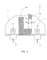
- Fig. 4 is a partial sectional side view of the CFB boiler according to a second embodiment, illustrating the flow control barrier located upstream of the fluidizing means located downstream of the opening.
- the present invention relates generally to the field of circulating fluidized bed (CFB) reactors or boilers such as those used in industrial or electric power generation facilities and, in particular but not exclusively, to a non-mechanical valve for controlling solids discharge from an in-bed heat exchanger (IBHX) to the CFB.
- CFB circulating fluidized bed
- IBHX in-bed heat exchanger
- CFB boiler will be used to refer to CFB reactors or combustors wherein a combustion process takes place. While the present invention is directed particularly to boilers or steam generators which employ CFB combustors as the means by which the heat is produced, it is understood that the present invention can readily be employed in a different kind of CFB reactor. For example, the invention could be applied in a reactor that is employed for chemical reactions other than a combustion process, or where a gas/solids mixture from a combustion process occurring elsewhere is provided to the reactor for further processing, or where the reactor merely provides an enclosure where particles or solids are entrained in a gas that is not necessarily a byproduct of the combustion process.
- a CFB reactor or boiler having a CFB reaction chamber 1 which comprises walls 2 (2a, 2b, 2c and 2d) and an IBHX 3 immersed in a BFB 4.
- the CFB within the reaction chamber 1 is predominantly comprised of solids made up of the ash from combustion of the fuel 5, sulfated sorbent 6 and, in some cases, external inert material 7 fed through at least one of the walls 2 and fluidized by primary air 8 supplied through a distribution grid 9 comprising a part of the reaction chamber floor.
- Some solids are entrained by gases resulting from the fuel combustion process and move upward as at 15 eventually reaching a particle separator 16, such as an impact-type particle separator or U-beams, at the reaction chamber exit. While some of the solids 17 pass the separator 16, the bulk of them 18 are captured and recycled back into the reaction chamber 1. Those solids along with others 19, falling out of the upflow solids stream 15, feed the BFB 4 that is being fluidized by fluidizing medium 25 fed through a distribution grid 26 comprising another part of the reaction chamber floor. Means 27 and 28, respectively, for removing solids from the CFB 1 and BFB 4, are provided in the pertinent areas of the reaction chamber floor.
- the BFB 4 is separated from the CFB 1 by an enclosure 30.
- the walls forming the BFB enclosure 30 may be constructed in several ways. In the present example, the enclosure walls would be comprised of fluid cooled tubes 50 (shown in Fig. 3 ) covered with erosion resistant material such as refractory to prevent erosion of the tubes during operation.
- the tubes 50 forming the enclosure 30 extend upward to an elevation allowing the required BFB 4 height within the CFB reaction chamber 1. Above the required height, the tubes 50 group to form secondary air nozzles 55. Air 60 fed to these nozzles is injected into the CFB 1 beyond the BFB 4, thus its jets 65 do not deflect streams of solids 18 and 19 from falling onto the BFB 4.
- the tubes 50 allows forming openings 70 through which the solids streams 18 and 19 fall onto the BFB 4. After reaching the wall 2b, the tubes 50 become part of the wall. Secondary air nozzles 75 on the opposite wall 2d are located externally to the CFB reaction chamber 1. Since no IBHX 3 is placed below the nozzles 75, their jets 80 do not cause any undesired effect.
- Fig. 3 shows an enlarged view of the area around the non-mechanical valve 40.
- the valve comprises an opening 85 in the enclosure 30 and independently controlled fluidizing means 86 and 87, located respectively upstream and downstream of the opening 85.
- These fluidizing means can be implemented as a number of bubble caps connected to a corresponding source of fluidizing medium, 46 and 45, respectively.
- the most common design of a distribution grid would be an array of bubble caps fed from a corresponding source of fluidizing medium, i.e. 8 for the CFB and 25 for the BFB.
- a bubble cap is comprised of a bubble cap proper and a supply pipe, typically referred to as the stem, which interconnects the fluidizing medium with the fluidized bed.
- Fluidizing gas is conveyed upwardly along the stem into the bubble cap, from which it is distributed to the fluidized bed via a plurality of outlet holes. Jets of fluidizing gas exiting from the outlet holes penetrate into the CFB or BFB bed providing its fluidization gas in the area around each bubble cap. To prevent erosion of the bubble caps in the vicinity of the opening 85 by the solids flow through the opening, the tops of the bubble caps should not be higher than the bottom of the opening 85.
- a flow control barrier 90 can be placed downstream of the opening 85. It provides a restriction to the solids flow through the opening 85 and also deflects the solids jet from the opening away from the bubble caps 9 or other fluidizing means in the CFB reaction chamber 1.
- a flow control barrier 90 is placed downstream (see Fig. 3 ) of the fluidizing means 87.
- a flow control barrier is placed upstream (see Fig. 4 ) of the fluidizing means 87.
- the top of the flow control barrier 90 will be at least as high as the bottom of the opening 85 and may be higher than the top of the opening 85.
- the flow control barrier will be subject to high bed temperatures and substantial erosion impact from the solids flowing through the opening 85. Thus it would be made of high temperature and erosion resistant material, e.g. ceramics or firebrick. Other options include making it of refractory-covered tubes.
- the heating surface of the IBHX 3, which absorbs heat from the BFB 4, may be a superheater, reheater, economizer, evaporative or combinations of such types of heating surfaces which are known to those skilled in the art.
- the heating surface is typically comprised of tubes 91 which convey a heat transfer medium therethrough, such as water, a two-phase mix of water and steam, or steam.
- Their general erosion potential is low due to the low fluidizing velocity in the BFB 4 as well as the low velocity of solids throughput across the IBHX 3.
- the velocity of solids travelling toward the opening increases substantially, which could increase the potential for erosion of the tubes 91.
- the tubes 91 In order to reduce or prevent erosion of the tubes 91, it may thus be appropriate for them to be arranged so that they are not in the vicinity of the opening 85 (as shown in Fig. 3 ). Expected erosion rates can be estimated based upon an evaluation of the local solids velocity in the vicinity of the opening 85 (as determined by the volumetric discharge rate through the opening 85), as well as upon a consideration of the erosive characteristics of the solids. Based upon the erosion rate that can be tolerated, and the estimated erosion rate determined using the principles described above, the tubes 91 can be located to reduce erosion. Thus, as shown in Fig.
- the ends of the lower tubes 91 in the IBHX 3 are not in the vicinity of the opening 85 since they do not extend as close to the enclosure wall 30 and opening 85 as other tubes 91 in the IBHX 3.
- parts of the tubes 91 adjacent to the opening 85 may be protected by a layer of erosion-resistant material 95, e.g. refractory held by studs welded to the tubes 91.
- Control of the solids discharge from the BFB 4 to the CFB 1 is accomplished by controlling fluidizing medium flow rates 45 and 46. Gas flow to the vicinity of the solids control valve promotes solids discharge from the lower part of the BFB 4 into the CFB 1. Independent control of these flow rates, e.g. turning them on and off in alternate cycles, allows for smoothing the solids discharge rate.
- Particular fluidizing medium control patterns (frequency of cycling, length of a cycle, etc.) depend on properties of the bed material and boiler operation requirements and should be established during boiler commissioning.
Landscapes
- Engineering & Computer Science (AREA)
- Chemical & Material Sciences (AREA)
- Combustion & Propulsion (AREA)
- Mechanical Engineering (AREA)
- General Engineering & Computer Science (AREA)
- Physics & Mathematics (AREA)
- Thermal Sciences (AREA)
- Fluidized-Bed Combustion And Resonant Combustion (AREA)
- Devices And Processes Conducted In The Presence Of Fluids And Solid Particles (AREA)
Applications Claiming Priority (1)
| Application Number | Priority Date | Filing Date | Title |
|---|---|---|---|
| US12/570,823 US8434430B2 (en) | 2009-09-30 | 2009-09-30 | In-bed solids control valve |
Publications (2)
| Publication Number | Publication Date |
|---|---|
| EP2348252A2 true EP2348252A2 (fr) | 2011-07-27 |
| EP2348252A3 EP2348252A3 (fr) | 2017-07-19 |
Family
ID=43778878
Family Applications (1)
| Application Number | Title | Priority Date | Filing Date |
|---|---|---|---|
| EP10178226.6A Withdrawn EP2348252A3 (fr) | 2009-09-30 | 2010-09-22 | Valve de contrôle de solides dans un lit pour chaudière à lit fluidisé |
Country Status (15)
| Country | Link |
|---|---|
| US (1) | US8434430B2 (fr) |
| EP (1) | EP2348252A3 (fr) |
| KR (1) | KR101731267B1 (fr) |
| CN (1) | CN102032559B (fr) |
| AR (1) | AR080547A1 (fr) |
| AU (1) | AU2010219391B2 (fr) |
| BG (1) | BG110759A (fr) |
| BR (1) | BRPI1003398A2 (fr) |
| CA (1) | CA2715855A1 (fr) |
| CL (1) | CL2010001032A1 (fr) |
| CO (1) | CO6410027A1 (fr) |
| MX (1) | MX2010010571A (fr) |
| NZ (2) | NZ615432A (fr) |
| RU (1) | RU2542627C2 (fr) |
| UA (1) | UA104418C2 (fr) |
Cited By (3)
| Publication number | Priority date | Publication date | Assignee | Title |
|---|---|---|---|---|
| EP2884162A1 (fr) * | 2013-12-16 | 2015-06-17 | Doosan Lentjes GmbH | Échangeur de chaleur à lit fluidisé |
| EP2884164A1 (fr) * | 2013-12-16 | 2015-06-17 | Doosan Lentjes GmbH | Échangeur de chaleur à lit fluidisé |
| EP2884165A1 (fr) * | 2013-12-16 | 2015-06-17 | Doosan Lentjes GmbH | Échangeur de chaleur à lit fluidisé |
Families Citing this family (3)
| Publication number | Priority date | Publication date | Assignee | Title |
|---|---|---|---|---|
| US20140102342A1 (en) * | 2012-10-17 | 2014-04-17 | Babcock & Wilcox Power Generation Group, Inc. | In-bed solids control valve with improved reliability |
| US20170356642A1 (en) | 2016-06-13 | 2017-12-14 | The Babcock & Wilcox Company | Circulating fluidized bed boiler with bottom-supported in-bed heat exchanger |
| FI127753B (en) * | 2017-06-09 | 2019-01-31 | Bioshare Ab | Recycling of chemicals from fuel streams |
Citations (1)
| Publication number | Priority date | Publication date | Assignee | Title |
|---|---|---|---|---|
| US6532905B2 (en) | 2001-07-17 | 2003-03-18 | The Babcock & Wilcox Company | CFB with controllable in-bed heat exchanger |
Family Cites Families (17)
| Publication number | Priority date | Publication date | Assignee | Title |
|---|---|---|---|---|
| ATE85682T1 (de) * | 1987-07-20 | 1993-02-15 | Ebara Corp | Wirbelbettofen mit innerer umwaelzung und verfahren zur steuerung desselben. |
| SU1746129A1 (ru) * | 1990-06-07 | 1992-07-07 | Уральский политехнический институт им.С.М.Кирова | Котел с циркулирующим кип щим слоем |
| RU2028543C1 (ru) * | 1990-10-22 | 1995-02-09 | Всероссийский теплотехнический научно-исследовательский институт | Топочное устройство с циркулирующим кипящим слоем |
| US5140950A (en) * | 1991-05-15 | 1992-08-25 | Foster Wheeler Energy Corporation | Fluidized bed combustion system and method having an integral recycle heat exchanger with recycle rate control and backflow sealing |
| US5347953A (en) * | 1991-06-03 | 1994-09-20 | Foster Wheeler Energy Corporation | Fluidized bed combustion method utilizing fine and coarse sorbent feed |
| US5239946A (en) * | 1992-06-08 | 1993-08-31 | Foster Wheeler Energy Corporation | Fluidized bed reactor system and method having a heat exchanger |
| US5406914A (en) * | 1992-11-10 | 1995-04-18 | A. Ahlstrom Corporation | Method and apparatus for operating a circulating fluidized bed reactor system |
| US5332553A (en) * | 1993-04-05 | 1994-07-26 | A. Ahlstrom Corporation | Method for circulating solid material in a fluidized bed reactor |
| ATE142163T1 (de) * | 1992-11-10 | 1996-09-15 | Foster Wheeler Energia Oy | Verfahren und vorrichtung zum transport von festen partikeln zwischen räumen |
| US5347954A (en) * | 1993-07-06 | 1994-09-20 | Foster Wheeler Energy Corporation | Fluidized bed combustion system having an improved pressure seal |
| US5533471A (en) * | 1994-08-17 | 1996-07-09 | A. Ahlstrom Corporation | fluidized bed reactor and method of operation thereof |
| US5526775A (en) * | 1994-10-12 | 1996-06-18 | Foster Wheeler Energia Oy | Circulating fluidized bed reactor and method of operating the same |
| UA42091C2 (uk) * | 1995-12-01 | 2001-10-15 | Дзе Бебкок Енд Уілкокс Компані, Корпорація Штату Делавер | Реактор з циркулюючим псевдозрідженим шаром |
| FI962653A7 (fi) * | 1996-06-27 | 1997-12-28 | Foster Wheeler Energia Oy | Menetelmä ja laite kiinteistä hiukkasista tapahtuvan lämmön siirtymisen valvomiseksi leijupetireaktorissa |
| FI107758B (fi) * | 1999-11-10 | 2001-09-28 | Foster Wheeler Energia Oy | Kiertoleijureaktori |
| US7464669B2 (en) * | 2006-04-19 | 2008-12-16 | Babcock & Wilcox Power Generation Group, Inc. | Integrated fluidized bed ash cooler |
| KR100759237B1 (ko) * | 2006-06-23 | 2007-09-17 | (주) 대주인테크 | 슬러지 건조시스템 |
-
2009
- 2009-09-30 US US12/570,823 patent/US8434430B2/en not_active Expired - Fee Related
-
2010
- 2010-09-10 AU AU2010219391A patent/AU2010219391B2/en not_active Ceased
- 2010-09-20 BR BRPI1003398-0A patent/BRPI1003398A2/pt active Search and Examination
- 2010-09-22 EP EP10178226.6A patent/EP2348252A3/fr not_active Withdrawn
- 2010-09-23 RU RU2010139127/06A patent/RU2542627C2/ru active
- 2010-09-24 MX MX2010010571A patent/MX2010010571A/es active IP Right Grant
- 2010-09-24 CA CA2715855A patent/CA2715855A1/fr not_active Abandoned
- 2010-09-28 KR KR1020100093545A patent/KR101731267B1/ko not_active Expired - Fee Related
- 2010-09-29 BG BG10110759A patent/BG110759A/bg unknown
- 2010-09-29 CN CN201010505906.0A patent/CN102032559B/zh not_active Expired - Fee Related
- 2010-09-29 AR ARP100103521A patent/AR080547A1/es active IP Right Grant
- 2010-09-29 UA UAA201011597A patent/UA104418C2/uk unknown
- 2010-09-29 CL CL2010001032A patent/CL2010001032A1/es unknown
- 2010-09-29 NZ NZ61543210A patent/NZ615432A/en not_active IP Right Cessation
- 2010-09-29 NZ NZ599126A patent/NZ599126A/xx not_active IP Right Cessation
- 2010-09-30 CO CO10121092A patent/CO6410027A1/es unknown
Patent Citations (1)
| Publication number | Priority date | Publication date | Assignee | Title |
|---|---|---|---|---|
| US6532905B2 (en) | 2001-07-17 | 2003-03-18 | The Babcock & Wilcox Company | CFB with controllable in-bed heat exchanger |
Cited By (4)
| Publication number | Priority date | Publication date | Assignee | Title |
|---|---|---|---|---|
| EP2884162A1 (fr) * | 2013-12-16 | 2015-06-17 | Doosan Lentjes GmbH | Échangeur de chaleur à lit fluidisé |
| EP2884164A1 (fr) * | 2013-12-16 | 2015-06-17 | Doosan Lentjes GmbH | Échangeur de chaleur à lit fluidisé |
| EP2884165A1 (fr) * | 2013-12-16 | 2015-06-17 | Doosan Lentjes GmbH | Échangeur de chaleur à lit fluidisé |
| WO2015090636A1 (fr) * | 2013-12-16 | 2015-06-25 | Doosan Lentjes Gmbh | Appareil à lit fluidisé et ses composants |
Also Published As
| Publication number | Publication date |
|---|---|
| AU2010219391A1 (en) | 2011-04-14 |
| EP2348252A3 (fr) | 2017-07-19 |
| UA104418C2 (uk) | 2014-02-10 |
| CN102032559B (zh) | 2014-11-26 |
| RU2542627C2 (ru) | 2015-02-20 |
| US8434430B2 (en) | 2013-05-07 |
| AU2010219391B2 (en) | 2016-05-19 |
| AR080547A1 (es) | 2012-04-18 |
| BG110759A (bg) | 2011-03-31 |
| CL2010001032A1 (es) | 2011-07-15 |
| MX2010010571A (es) | 2011-03-30 |
| KR101731267B1 (ko) | 2017-04-28 |
| NZ599126A (en) | 2013-10-25 |
| KR20110035923A (ko) | 2011-04-06 |
| NZ615432A (en) | 2015-04-24 |
| CO6410027A1 (es) | 2012-03-30 |
| BRPI1003398A2 (pt) | 2013-01-08 |
| CA2715855A1 (fr) | 2011-03-30 |
| RU2010139127A (ru) | 2012-03-27 |
| US20110073049A1 (en) | 2011-03-31 |
| CN102032559A (zh) | 2011-04-27 |
Similar Documents
| Publication | Publication Date | Title |
|---|---|---|
| US6532905B2 (en) | CFB with controllable in-bed heat exchanger | |
| FI92099B (fi) | Kiertomassatyyppinen leijukerrosreaktori | |
| US8434430B2 (en) | In-bed solids control valve | |
| EP2908936B1 (fr) | Vanne de régulation de solides intégrée au lit présentant une fiabilité améliorée | |
| RU2537482C2 (ru) | Циркулирующий псевдоожиженный слой с соплами для подачи вторичного воздуха в топочную камеру | |
| US10018353B2 (en) | Sealpot and method for controlling a solids flow rate therethrough | |
| EP3222911B1 (fr) | Échangeur de chaleur à lit fluidisé et appareil d'incinération correspondant |
Legal Events
| Date | Code | Title | Description |
|---|---|---|---|
| PUAI | Public reference made under article 153(3) epc to a published international application that has entered the european phase |
Free format text: ORIGINAL CODE: 0009012 |
|
| AK | Designated contracting states |
Kind code of ref document: A2 Designated state(s): AL AT BE BG CH CY CZ DE DK EE ES FI FR GB GR HR HU IE IS IT LI LT LU LV MC MK MT NL NO PL PT RO SE SI SK SM TR |
|
| AX | Request for extension of the european patent |
Extension state: BA ME RS |
|
| RAP1 | Party data changed (applicant data changed or rights of an application transferred) |
Owner name: THE BABCOCK & WILCOX COMPANY |
|
| PUAL | Search report despatched |
Free format text: ORIGINAL CODE: 0009013 |
|
| AK | Designated contracting states |
Kind code of ref document: A3 Designated state(s): AL AT BE BG CH CY CZ DE DK EE ES FI FR GB GR HR HU IE IS IT LI LT LU LV MC MK MT NL NO PL PT RO SE SI SK SM TR |
|
| AX | Request for extension of the european patent |
Extension state: BA ME RS |
|
| RIC1 | Information provided on ipc code assigned before grant |
Ipc: F22B 31/00 20060101AFI20170614BHEP |
|
| STAA | Information on the status of an ep patent application or granted ep patent |
Free format text: STATUS: REQUEST FOR EXAMINATION WAS MADE |
|
| 17P | Request for examination filed |
Effective date: 20180119 |
|
| RBV | Designated contracting states (corrected) |
Designated state(s): AL AT BE BG CH CY CZ DE DK EE ES FI FR GB GR HR HU IE IS IT LI LT LU LV MC MK MT NL NO PL PT RO SE SI SK SM TR |
|
| RAP1 | Party data changed (applicant data changed or rights of an application transferred) |
Owner name: THE BABCOCK & WILCOX COMPANY |
|
| STAA | Information on the status of an ep patent application or granted ep patent |
Free format text: STATUS: EXAMINATION IS IN PROGRESS |
|
| 17Q | First examination report despatched |
Effective date: 20200710 |
|
| STAA | Information on the status of an ep patent application or granted ep patent |
Free format text: STATUS: THE APPLICATION HAS BEEN WITHDRAWN |
|
| 18W | Application withdrawn |
Effective date: 20201029 |