EP2348376A1 - Vanne de contrôle de débit dotée d'une chambre d'amortissement - Google Patents
Vanne de contrôle de débit dotée d'une chambre d'amortissement Download PDFInfo
- Publication number
- EP2348376A1 EP2348376A1 EP20110000251 EP11000251A EP2348376A1 EP 2348376 A1 EP2348376 A1 EP 2348376A1 EP 20110000251 EP20110000251 EP 20110000251 EP 11000251 A EP11000251 A EP 11000251A EP 2348376 A1 EP2348376 A1 EP 2348376A1
- Authority
- EP
- European Patent Office
- Prior art keywords
- valve
- piston
- pressure
- valve housing
- valve according
- Prior art date
- Legal status (The legal status is an assumption and is not a legal conclusion. Google has not performed a legal analysis and makes no representation as to the accuracy of the status listed.)
- Granted
Links
Images
Classifications
-
- G—PHYSICS
- G05—CONTROLLING; REGULATING
- G05D—SYSTEMS FOR CONTROLLING OR REGULATING NON-ELECTRIC VARIABLES
- G05D7/00—Control of flow
- G05D7/005—Control of flow characterised by the use of auxiliary non-electric power combined with the use of electric means
-
- Y—GENERAL TAGGING OF NEW TECHNOLOGICAL DEVELOPMENTS; GENERAL TAGGING OF CROSS-SECTIONAL TECHNOLOGIES SPANNING OVER SEVERAL SECTIONS OF THE IPC; TECHNICAL SUBJECTS COVERED BY FORMER USPC CROSS-REFERENCE ART COLLECTIONS [XRACs] AND DIGESTS
- Y10—TECHNICAL SUBJECTS COVERED BY FORMER USPC
- Y10T—TECHNICAL SUBJECTS COVERED BY FORMER US CLASSIFICATION
- Y10T137/00—Fluid handling
- Y10T137/2496—Self-proportioning or correlating systems
- Y10T137/2559—Self-controlled branched flow systems
- Y10T137/2574—Bypass or relief controlled by main line fluid condition
- Y10T137/2579—Flow rate responsive
- Y10T137/2594—Choke
- Y10T137/2597—Variable choke resistance
-
- Y—GENERAL TAGGING OF NEW TECHNOLOGICAL DEVELOPMENTS; GENERAL TAGGING OF CROSS-SECTIONAL TECHNOLOGIES SPANNING OVER SEVERAL SECTIONS OF THE IPC; TECHNICAL SUBJECTS COVERED BY FORMER USPC CROSS-REFERENCE ART COLLECTIONS [XRACs] AND DIGESTS
- Y10—TECHNICAL SUBJECTS COVERED BY FORMER USPC
- Y10T—TECHNICAL SUBJECTS COVERED BY FORMER US CLASSIFICATION
- Y10T137/00—Fluid handling
- Y10T137/2496—Self-proportioning or correlating systems
- Y10T137/2559—Self-controlled branched flow systems
- Y10T137/2574—Bypass or relief controlled by main line fluid condition
- Y10T137/2605—Pressure responsive
- Y10T137/2612—Common sensor for both bypass or relief valve and other branch valve
- Y10T137/2615—Bypass or relief valve opens as other branch valve closes
-
- Y—GENERAL TAGGING OF NEW TECHNOLOGICAL DEVELOPMENTS; GENERAL TAGGING OF CROSS-SECTIONAL TECHNOLOGIES SPANNING OVER SEVERAL SECTIONS OF THE IPC; TECHNICAL SUBJECTS COVERED BY FORMER USPC CROSS-REFERENCE ART COLLECTIONS [XRACs] AND DIGESTS
- Y10—TECHNICAL SUBJECTS COVERED BY FORMER USPC
- Y10T—TECHNICAL SUBJECTS COVERED BY FORMER US CLASSIFICATION
- Y10T137/00—Fluid handling
- Y10T137/2496—Self-proportioning or correlating systems
- Y10T137/2559—Self-controlled branched flow systems
- Y10T137/2574—Bypass or relief controlled by main line fluid condition
- Y10T137/2605—Pressure responsive
- Y10T137/263—Plural sensors for single bypass or relief valve
- Y10T137/2632—Sensors interconnected by timing or restrictive orifice
-
- Y—GENERAL TAGGING OF NEW TECHNOLOGICAL DEVELOPMENTS; GENERAL TAGGING OF CROSS-SECTIONAL TECHNOLOGIES SPANNING OVER SEVERAL SECTIONS OF THE IPC; TECHNICAL SUBJECTS COVERED BY FORMER USPC CROSS-REFERENCE ART COLLECTIONS [XRACs] AND DIGESTS
- Y10—TECHNICAL SUBJECTS COVERED BY FORMER USPC
- Y10T—TECHNICAL SUBJECTS COVERED BY FORMER US CLASSIFICATION
- Y10T137/00—Fluid handling
- Y10T137/7722—Line condition change responsive valves
- Y10T137/7781—With separate connected fluid reactor surface
- Y10T137/7784—Responsive to change in rate of fluid flow
- Y10T137/7787—Expansible chamber subject to differential pressures
- Y10T137/7788—Pressures across fixed choke
-
- Y—GENERAL TAGGING OF NEW TECHNOLOGICAL DEVELOPMENTS; GENERAL TAGGING OF CROSS-SECTIONAL TECHNOLOGIES SPANNING OVER SEVERAL SECTIONS OF THE IPC; TECHNICAL SUBJECTS COVERED BY FORMER USPC CROSS-REFERENCE ART COLLECTIONS [XRACs] AND DIGESTS
- Y10—TECHNICAL SUBJECTS COVERED BY FORMER USPC
- Y10T—TECHNICAL SUBJECTS COVERED BY FORMER US CLASSIFICATION
- Y10T137/00—Fluid handling
- Y10T137/7722—Line condition change responsive valves
- Y10T137/7837—Direct response valves [i.e., check valve type]
- Y10T137/7904—Reciprocating valves
Definitions
- the invention relates to a valve, in particular a flow control valve according to the preamble of patent claim 1.
- flow control valves are valves that serve to regulate the flow rate of a fluid used.
- a throttle valve as a subset of a flow control valve, is an adjustable valve-threaded restriction in line flow.
- the volume flow also changes as a function of the pressure gradient that occurs across the valve.
- a flow control valve as a further subgroup of a flow control valve is in addition to the aforementioned throttle valve additionally equipped with a pressure compensation. As a result, a set volume flow remains unchanged even when a pressure gradient that changes across the valve is changed, i. the volume flow is independent of the actual pressure drop across the valve.
- an adjustable metering orifice is associated with a pressure compensator, which is acted upon by a spring force and a pressure prevailing downstream of the metering orifice in the opening direction and by a pressure prevailing in the closing direction upstream of the metering orifice.
- This pressure compensator can in principle be directly upstream or downstream of the variable orifice plate, as well as integrated in the metering orifice.
- a dosing guide member In the compensating piston is mounted a dosing guide member, wherein a control piston is slidably disposed within the guide member.
- a damping guide member In the axial distance to the metering-guide member, a damping guide member is further provided slidably within the compensation piston, which forms a damper chamber in the compensation piston.
- a biasing spring is used, which biases the damping guide member in one direction to come into contact with the metering-guide member frontally and biases the compensation piston in an opposite direction to the housing end face in Plant to come.
- a control spring In the hollow control piston, a control spring is used, which presses the control piston end face against the damping guide element.
- a cartridge housing is provided in which a pilot valve assembly is housed and which is mounted via an adapter on the valve housing.
- An object of the present invention to provide a valve of this type, which has a simpler structure.
- An object of the invention is to reduce the susceptibility to interference and to make the valve more flexible for individual application requirements by providing a system tuning capability.
- valve preferably for setting a pressure medium volume flow with the features of patent claim 1.
- Advantageous embodiments are the subject of the dependent claims.
- the basic principle of the invention is accordingly to form a damping chamber by a directly on the valve housing mounted valve piston under the interaction of these two components, ie, the damping chamber is formed between the valve piston and the valve housing (cartridge). This simplifies the entire design of the valve.
- the damping effect is set or adjustable by a throttle opening fluidly connected to the damping chamber.
- the damping chamber is further preferably formed at an axial end portion of the valve piston between the valve piston, the valve housing and an axial end plate, in which the valve piston is guided in the axial direction.
- the throttle opening is advantageously formed by an annular gap between the cover disk and the valve piston and / or by at least one bore in the cover disk. This results in a very compact and at the same time simple construction, whereby manufacturing costs are reduced. At the same time, it is possible to prepare end plates with different bore diameters and thus different throttle values and to install them as required. In this way, the damping effect of the valve can be easily adapted to the characteristics of a fluid system in which the valve according to the invention is to be installed. This increases the functionality and flexibility of the valve.
- cover plate is held by a securing ring, which is preferably designed as a spring ring and engages positively in an inner circumferential groove in the valve housing.
- valve piston has a sliding portion, which is in sliding contact with the valve housing and which is bounded at the one axial end portion of the valve piston by a radial recess which is slidably received in the cover plate and thereby the damping chamber axially between the cover disc and the sliding portion of the valve piston and radially defined between the valve piston and the valve housing.
- the volume of the damping chamber can be adjusted by small machining measures individually to the conditions of the respective fluid system.
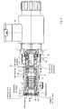
- the flow control valve according to the invention has a cartridge-shaped housing in the form of a sleeve, which is formed on its outer circumferential surface with a number of axially spaced radial stages 2.
- the sleeve 1 has at an axial end portion a radially projecting stop ring 4, which is directly upstream of a male threaded portion 6, so that the sleeve 1 can be screwed, for example, in a valve block, not shown.
- an axial port P is preferably provided for the connection of a (not shown) Druckstoffzuclass issued.
- the sleeve 1 is formed with an inner circumferential groove 8, which is followed by a circumferential inner radial shoulder with a smaller diameter at a small axial distance.
- a cover plate 12 is inserted, which is held by a retaining ring 14 (spring ring) as axially as possible without play, which is snapped into the circumferential groove 8.
- a hollow / sleeve-shaped pressure balance piston 16 is inserted axially displaceable, which has an axially extending sliding portion 16a, which is directly in sliding contact with the sleeve 1 at the inner wall.
- this has a radial outer recess 16b, which extends from the sliding portion 16a to the end plate 12 facing the end face of the pressure compensator piston 16.
- a through hole or opening is formed, such that the pressure balance piston 16 in the region of its outer radial recess 16a in the cover plate 12 slidably (centrally) can be introduced.
- an annular space 18 is formed between the pressure piston 16, the inner sleeve wall and the cover plate 12, which defines a damping chamber 18 described below.
- at least one further decentral through-bore 20 with a predetermined (small) diameter is formed in the cover disk 16, which connects the damping chamber with the axial port P and defines a throttle nozzle to be described below.
- the housing sleeve 1 has at least one radial through-bore 22 in an axial middle section, which constitutes an outlet connection A of the valve according to the invention.
- the pressure compensator piston 16 has an axial length which is defined such that the pressure balance piston 16 completely closes the radial bore 22 in the housing sleeve in a first retracted position (at a maximum distance to the end disk 12). In this position, the damping chamber 18 has a maximum volume of space.
- the inner axial end face of the pressure compensating piston 16 forms with the housing sleeve 1 in the region of the radial bore 22 formed therein a control diaphragm R of the valve.
- the pressure balance piston 16 is further biased by a biasing spring 24 in the direction of the cover plate 12 for opening the radial bore 22 in the housing sleeve 1.
- this biasing spring 24 is inserted in the hollow pressure compensating piston 16 and for this purpose is axially supported on a radially inwardly projecting circumferential projection 16c on the pressure compensating piston 16.
- a counter-aligned spring seat is further formed by a guide sleeve 26 which is slidably inserted into the pressure compensating piston 16 at an end portion facing away from the end plate 12 and at the same time forms an axial stop for the pressure compensating piston 16 for defining the first position of the pressure compensating piston 16 described above.
- the guide sleeve 26 has at one end portion a radially outer shoulder 26a, which can be brought into operative engagement with the pressure balance piston 16 for an axial stop.
- the guide sleeve 26 further has at least at its other end portion an outer peripheral surface 26b, which is preferably in sealing contact with the housing sleeve 1 on the inner wall thereof.
- an axially extending circumferential annular space 28 is formed, which is axially bounded by the pressure balance piston 16.
- an actuating piston 34 in the form of a sleeve is slidably and sealingly inserted from its side facing away from the pressure compensator piston 16.
- This actuating piston 34 has in a central portion a number of radial bores 36 which form an adjustable orifice plate M with the at least one radial bore 30 in the guide sleeve 26. That is, depending on the axial relative position between the actuating piston 34 and the guide sleeve 26, the orifice M formed by the respective radial bores 30, 36 partially opens in a predetermined manner, whereby the annular space formed by the radially outer periphery of the guide sleeve 26 provides fluid access receives to the axial port P of the valve.
- the actuating piston 34 is in the present embodiment according to the Fig. 1 directly controlled, ie preferably operated by means of an electromagnetic actuator 38 in the axial direction, wherein the actuating piston 34 additionally by means of a spring 40 in a according to the Fig. 1 illustrated closing position is biased, in which the through the radial bores 30, 36 formed in the actuating piston 34 and the surrounding guide sleeve 26 measuring orifice M is completely closed.
- the pressure balance piston 16 is formed in an axial portion immediately behind the damping chamber 18 with a number of radial bores 42 which can be connected in dependence on the axial position of the pressure compensator piston 16 with respect to the housing sleeve 1 with a further radial bore 44 in the housing sleeve 1, thereby to open a bypass circuit T, as will be described below.
- the preferably electromagnetic actuator 38 is actuated, this exerts an axial force on the actuating piston 34, against the Stellfederkraft, and moves it in the axial direction to the cover plate 12.
- formed between the guide sleeve 26 and the actuating piston 34 orifice M is set according to the Control value of the actuating piston 34 is opened and thus created a restricted access between the axial port P of the valve and between the guide sleeve 26 and the housing sleeve 1 forming annular space 28.
- the resulting annular space pressure causes an axial displacement of the pressure compensating piston in the direction of the end plate 12, wherein this displacement movement is damped by a throttled outflow of pressure medium from the damping chamber 18 via the axial throttle bore 20 (or annular gap).
- the regulating diaphragm R which is formed between the pressure compensating piston 16 and the housing sleeve 1, opens, whereby a throttled opening is created between the annular space 28 and the outlet port A of the valve.
- the connection between the axial connection P and the bypass circuit T is closed by the axial movement of the pressure compensating piston 16. Therefore, now pressure medium via the axial connection P, the measuring orifice M, the annular space 28 and the control panel R flow into the outlet port A of the valve.
- the flow control valve with integrated pressure compensator and damping chamber can also be modified by replacing the above-described direct control of the actuating piston 34 by a pilot mechanism.
- the preferably electromagnetic drive 38 confirms a pilot valve, via which the actuating piston 34 is axially adjustable.
Landscapes
- Engineering & Computer Science (AREA)
- Power Engineering (AREA)
- Physics & Mathematics (AREA)
- General Physics & Mathematics (AREA)
- Automation & Control Theory (AREA)
- Safety Valves (AREA)
- Control Of Fluid Pressure (AREA)
Applications Claiming Priority (1)
| Application Number | Priority Date | Filing Date | Title |
|---|---|---|---|
| DE102010005524A DE102010005524A1 (de) | 2010-01-23 | 2010-01-23 | Stromregelventil mit Dämpfungskammer |
Publications (2)
| Publication Number | Publication Date |
|---|---|
| EP2348376A1 true EP2348376A1 (fr) | 2011-07-27 |
| EP2348376B1 EP2348376B1 (fr) | 2013-05-29 |
Family
ID=43646470
Family Applications (1)
| Application Number | Title | Priority Date | Filing Date |
|---|---|---|---|
| EP20110000251 Active EP2348376B1 (fr) | 2010-01-23 | 2011-01-14 | Vanne de contrôle de débit dotée d'une chambre d'amortissement |
Country Status (3)
| Country | Link |
|---|---|
| US (1) | US8662097B2 (fr) |
| EP (1) | EP2348376B1 (fr) |
| DE (1) | DE102010005524A1 (fr) |
Families Citing this family (10)
| Publication number | Priority date | Publication date | Assignee | Title |
|---|---|---|---|---|
| JP5453918B2 (ja) * | 2009-05-18 | 2014-03-26 | トヨタ自動車株式会社 | 流量制御弁 |
| DE102009049548A1 (de) * | 2009-10-16 | 2011-04-21 | Hydac Fluidtechnik Gmbh | Ventilanordnung |
| US9518670B2 (en) * | 2013-03-15 | 2016-12-13 | David E Albrecht | Main stage in-line pressure control cartridge with stepped retainer collar |
| US9091355B2 (en) * | 2013-03-15 | 2015-07-28 | David Albrecht | Main stage in-line pressure control cartridge with optional reverse flow function |
| US9777865B2 (en) * | 2014-04-15 | 2017-10-03 | Fema Corporation Of Michigan | Balanced electronically controlled pressure regulating valve |
| CN107965488A (zh) * | 2017-11-25 | 2018-04-27 | 宁波文泽机电技术开发有限公司 | 一种插装式比例流量阀 |
| CN107965490A (zh) * | 2017-11-25 | 2018-04-27 | 宁波文泽机电技术开发有限公司 | 比例调速阀 |
| CN107763000A (zh) * | 2017-11-25 | 2018-03-06 | 宁波文泽机电技术开发有限公司 | 反比例流量阀 |
| DE102018122437A1 (de) * | 2018-09-13 | 2020-03-19 | Eto Magnetic Gmbh | Proportionalventil |
| US20220325709A1 (en) * | 2019-07-11 | 2022-10-13 | Eagle Industry Co., Ltd. | Capacity control valve |
Citations (4)
| Publication number | Priority date | Publication date | Assignee | Title |
|---|---|---|---|---|
| US3724485A (en) * | 1971-05-12 | 1973-04-03 | Servo Labs Inc | Flow controller |
| WO1986000731A1 (fr) * | 1984-07-06 | 1986-01-30 | Brunswick Valve And Control, Inc. | Regulateur de debit a piston equilibre par la pression pour fournir un debit constant |
| US6966329B2 (en) | 2003-01-27 | 2005-11-22 | Hydraforce, Inc. | Proportional pilot-operated flow control valve |
| US20080230729A1 (en) * | 2005-10-20 | 2008-09-25 | Dominique Costaz | Valve With Cushioned Opening System |
Family Cites Families (11)
| Publication number | Priority date | Publication date | Assignee | Title |
|---|---|---|---|---|
| US4576200A (en) * | 1985-03-26 | 1986-03-18 | Applied Power Inc. | Hydraulic pressure reducing control valve |
| US4630640A (en) * | 1985-06-10 | 1986-12-23 | Sun Hydraulics Corp. | Pressure compensated restrictive flow regulator cartridge |
| US5184644A (en) * | 1991-05-30 | 1993-02-09 | Coltec Industries Inc. | Solenoid operated pressure regulating valve |
| US5836335A (en) * | 1991-08-19 | 1998-11-17 | Fluid Power Industries, Inc. | Proportional pressure control valve |
| DE4129828C1 (fr) * | 1991-09-07 | 1993-04-29 | Mercedes-Benz Aktiengesellschaft, 7000 Stuttgart, De | |
| US5639066A (en) * | 1995-06-15 | 1997-06-17 | Applied Power Inc. | Bidirectional flow control valve |
| US6029703A (en) * | 1998-12-18 | 2000-02-29 | Borg-Warner Automotive, Inc. | Pressure solenoid control valve with flux shunt |
| DE10037793B4 (de) * | 2000-08-03 | 2007-05-24 | Hydraulik-Ring Gmbh | Magnetventil, insbesondere Druckregelventil |
| US6615869B2 (en) * | 2001-03-26 | 2003-09-09 | Denso Corporation | Solenoid valve |
| JP4030491B2 (ja) * | 2003-10-15 | 2008-01-09 | 株式会社ケーヒン | 常開型油圧制御弁 |
| US7717128B2 (en) * | 2005-11-07 | 2010-05-18 | Arpad Matyas Pataki | Pressure balanced three-way valve for motion control |
-
2010
- 2010-01-23 DE DE102010005524A patent/DE102010005524A1/de not_active Withdrawn
-
2011
- 2011-01-14 EP EP20110000251 patent/EP2348376B1/fr active Active
- 2011-01-20 US US13/010,645 patent/US8662097B2/en not_active Expired - Fee Related
Patent Citations (4)
| Publication number | Priority date | Publication date | Assignee | Title |
|---|---|---|---|---|
| US3724485A (en) * | 1971-05-12 | 1973-04-03 | Servo Labs Inc | Flow controller |
| WO1986000731A1 (fr) * | 1984-07-06 | 1986-01-30 | Brunswick Valve And Control, Inc. | Regulateur de debit a piston equilibre par la pression pour fournir un debit constant |
| US6966329B2 (en) | 2003-01-27 | 2005-11-22 | Hydraforce, Inc. | Proportional pilot-operated flow control valve |
| US20080230729A1 (en) * | 2005-10-20 | 2008-09-25 | Dominique Costaz | Valve With Cushioned Opening System |
Also Published As
| Publication number | Publication date |
|---|---|
| DE102010005524A1 (de) | 2011-07-28 |
| US20110197979A1 (en) | 2011-08-18 |
| EP2348376B1 (fr) | 2013-05-29 |
| US8662097B2 (en) | 2014-03-04 |
Similar Documents
| Publication | Publication Date | Title |
|---|---|---|
| EP2348376B1 (fr) | Vanne de contrôle de débit dotée d'une chambre d'amortissement | |
| EP2382520B1 (fr) | Soupape de régulation de pression proportionnelle et son utilisation pour connection hydraulique | |
| EP1629336B1 (fr) | Soupape | |
| DE102007058620B3 (de) | Kolbenschieberventil | |
| EP1826649A2 (fr) | Distributeur ou régulateur de courant | |
| EP3001080A1 (fr) | Soupape de reduction de pression dotee d'alesages radiaux superposes pour differents chemins d'ecoulement de fluide | |
| EP1996821B1 (fr) | Agencement de soupape de regulation ludv | |
| EP2558758B1 (fr) | Régulateur de débit | |
| EP2880316B1 (fr) | Soupape, en particulier soupape à siège proportionnelle pilotée | |
| EP3295065B1 (fr) | Soupape, en particulier soupape proportionnelle de régulation de pression | |
| EP2880315B1 (fr) | Soupape, en particulier distributeur à siège proportionnel piloté | |
| EP2669528A2 (fr) | Agencement de soupapes hydrostatique et agencement de commande hydrostatique doté de l'agencement de soupapes | |
| EP1781953B1 (fr) | Soupape pilote, notamment pour des servo-soupapes | |
| EP1629209A1 (fr) | Ensemble commande hydraulique | |
| DE102014007475B4 (de) | Ventilanordnung zur gesteuerten Druckentlastung fluidgefüllter Leitungen unter erhöhten Sicherheitsanforderungen | |
| EP1452744B1 (fr) | Dispositif de contrôle hydraulique | |
| EP2044336B1 (fr) | Système de commande pour un élément hydraulique | |
| DE10245836B4 (de) | LS-Wegeventilanordnung | |
| DE102011117086A1 (de) | UND-Ventil | |
| DE102008000296A1 (de) | Elektromagnetisch betätigbares Sitzventil | |
| DE102007052602A1 (de) | Vorgesteuertes Wegeventil | |
| DE19960885B4 (de) | Stromregelventil | |
| EP1499807A1 (fr) | Ensemble distributeur ls | |
| WO2005106611A1 (fr) | Soupape de regulation de flux | |
| DE102012222173A1 (de) | Ventilanordnung zur Begrenzung der Druckanstiegsgeschwindigkeit |
Legal Events
| Date | Code | Title | Description |
|---|---|---|---|
| PUAI | Public reference made under article 153(3) epc to a published international application that has entered the european phase |
Free format text: ORIGINAL CODE: 0009012 |
|
| AK | Designated contracting states |
Kind code of ref document: A1 Designated state(s): AL AT BE BG CH CY CZ DE DK EE ES FI FR GB GR HR HU IE IS IT LI LT LU LV MC MK MT NL NO PL PT RO RS SE SI SK SM TR |
|
| AX | Request for extension of the european patent |
Extension state: BA ME |
|
| 17P | Request for examination filed |
Effective date: 20120127 |
|
| 17Q | First examination report despatched |
Effective date: 20120330 |
|
| GRAP | Despatch of communication of intention to grant a patent |
Free format text: ORIGINAL CODE: EPIDOSNIGR1 |
|
| GRAS | Grant fee paid |
Free format text: ORIGINAL CODE: EPIDOSNIGR3 |
|
| GRAA | (expected) grant |
Free format text: ORIGINAL CODE: 0009210 |
|
| AK | Designated contracting states |
Kind code of ref document: B1 Designated state(s): AL AT BE BG CH CY CZ DE DK EE ES FI FR GB GR HR HU IE IS IT LI LT LU LV MC MK MT NL NO PL PT RO RS SE SI SK SM TR |
|
| REG | Reference to a national code |
Ref country code: GB Ref legal event code: FG4D Free format text: NOT ENGLISH |
|
| REG | Reference to a national code |
Ref country code: CH Ref legal event code: EP |
|
| REG | Reference to a national code |
Ref country code: AT Ref legal event code: REF Ref document number: 614780 Country of ref document: AT Kind code of ref document: T Effective date: 20130615 |
|
| REG | Reference to a national code |
Ref country code: IE Ref legal event code: FG4D Free format text: LANGUAGE OF EP DOCUMENT: GERMAN |
|
| REG | Reference to a national code |
Ref country code: DE Ref legal event code: R096 Ref document number: 502011000775 Country of ref document: DE Effective date: 20130725 |
|
| REG | Reference to a national code |
Ref country code: LT Ref legal event code: MG4D |
|
| PG25 | Lapsed in a contracting state [announced via postgrant information from national office to epo] |
Ref country code: IS Free format text: LAPSE BECAUSE OF FAILURE TO SUBMIT A TRANSLATION OF THE DESCRIPTION OR TO PAY THE FEE WITHIN THE PRESCRIBED TIME-LIMIT Effective date: 20130929 Ref country code: NO Free format text: LAPSE BECAUSE OF FAILURE TO SUBMIT A TRANSLATION OF THE DESCRIPTION OR TO PAY THE FEE WITHIN THE PRESCRIBED TIME-LIMIT Effective date: 20130829 Ref country code: ES Free format text: LAPSE BECAUSE OF FAILURE TO SUBMIT A TRANSLATION OF THE DESCRIPTION OR TO PAY THE FEE WITHIN THE PRESCRIBED TIME-LIMIT Effective date: 20130909 Ref country code: FI Free format text: LAPSE BECAUSE OF FAILURE TO SUBMIT A TRANSLATION OF THE DESCRIPTION OR TO PAY THE FEE WITHIN THE PRESCRIBED TIME-LIMIT Effective date: 20130529 Ref country code: PT Free format text: LAPSE BECAUSE OF FAILURE TO SUBMIT A TRANSLATION OF THE DESCRIPTION OR TO PAY THE FEE WITHIN THE PRESCRIBED TIME-LIMIT Effective date: 20130930 Ref country code: SE Free format text: LAPSE BECAUSE OF FAILURE TO SUBMIT A TRANSLATION OF THE DESCRIPTION OR TO PAY THE FEE WITHIN THE PRESCRIBED TIME-LIMIT Effective date: 20130529 Ref country code: LT Free format text: LAPSE BECAUSE OF FAILURE TO SUBMIT A TRANSLATION OF THE DESCRIPTION OR TO PAY THE FEE WITHIN THE PRESCRIBED TIME-LIMIT Effective date: 20130529 Ref country code: GR Free format text: LAPSE BECAUSE OF FAILURE TO SUBMIT A TRANSLATION OF THE DESCRIPTION OR TO PAY THE FEE WITHIN THE PRESCRIBED TIME-LIMIT Effective date: 20130830 Ref country code: SI Free format text: LAPSE BECAUSE OF FAILURE TO SUBMIT A TRANSLATION OF THE DESCRIPTION OR TO PAY THE FEE WITHIN THE PRESCRIBED TIME-LIMIT Effective date: 20130529 |
|
| REG | Reference to a national code |
Ref country code: NL Ref legal event code: VDEP Effective date: 20130529 |
|
| PG25 | Lapsed in a contracting state [announced via postgrant information from national office to epo] |
Ref country code: HR Free format text: LAPSE BECAUSE OF FAILURE TO SUBMIT A TRANSLATION OF THE DESCRIPTION OR TO PAY THE FEE WITHIN THE PRESCRIBED TIME-LIMIT Effective date: 20130529 Ref country code: PL Free format text: LAPSE BECAUSE OF FAILURE TO SUBMIT A TRANSLATION OF THE DESCRIPTION OR TO PAY THE FEE WITHIN THE PRESCRIBED TIME-LIMIT Effective date: 20130529 Ref country code: RS Free format text: LAPSE BECAUSE OF FAILURE TO SUBMIT A TRANSLATION OF THE DESCRIPTION OR TO PAY THE FEE WITHIN THE PRESCRIBED TIME-LIMIT Effective date: 20130529 Ref country code: BG Free format text: LAPSE BECAUSE OF FAILURE TO SUBMIT A TRANSLATION OF THE DESCRIPTION OR TO PAY THE FEE WITHIN THE PRESCRIBED TIME-LIMIT Effective date: 20130829 |
|
| PG25 | Lapsed in a contracting state [announced via postgrant information from national office to epo] |
Ref country code: LV Free format text: LAPSE BECAUSE OF FAILURE TO SUBMIT A TRANSLATION OF THE DESCRIPTION OR TO PAY THE FEE WITHIN THE PRESCRIBED TIME-LIMIT Effective date: 20130529 |
|
| PG25 | Lapsed in a contracting state [announced via postgrant information from national office to epo] |
Ref country code: EE Free format text: LAPSE BECAUSE OF FAILURE TO SUBMIT A TRANSLATION OF THE DESCRIPTION OR TO PAY THE FEE WITHIN THE PRESCRIBED TIME-LIMIT Effective date: 20130529 Ref country code: SK Free format text: LAPSE BECAUSE OF FAILURE TO SUBMIT A TRANSLATION OF THE DESCRIPTION OR TO PAY THE FEE WITHIN THE PRESCRIBED TIME-LIMIT Effective date: 20130529 Ref country code: CZ Free format text: LAPSE BECAUSE OF FAILURE TO SUBMIT A TRANSLATION OF THE DESCRIPTION OR TO PAY THE FEE WITHIN THE PRESCRIBED TIME-LIMIT Effective date: 20130529 Ref country code: DK Free format text: LAPSE BECAUSE OF FAILURE TO SUBMIT A TRANSLATION OF THE DESCRIPTION OR TO PAY THE FEE WITHIN THE PRESCRIBED TIME-LIMIT Effective date: 20130529 |
|
| PG25 | Lapsed in a contracting state [announced via postgrant information from national office to epo] |
Ref country code: NL Free format text: LAPSE BECAUSE OF FAILURE TO SUBMIT A TRANSLATION OF THE DESCRIPTION OR TO PAY THE FEE WITHIN THE PRESCRIBED TIME-LIMIT Effective date: 20130529 Ref country code: RO Free format text: LAPSE BECAUSE OF FAILURE TO SUBMIT A TRANSLATION OF THE DESCRIPTION OR TO PAY THE FEE WITHIN THE PRESCRIBED TIME-LIMIT Effective date: 20130529 |
|
| PLBE | No opposition filed within time limit |
Free format text: ORIGINAL CODE: 0009261 |
|
| STAA | Information on the status of an ep patent application or granted ep patent |
Free format text: STATUS: NO OPPOSITION FILED WITHIN TIME LIMIT |
|
| 26N | No opposition filed |
Effective date: 20140303 |
|
| REG | Reference to a national code |
Ref country code: DE Ref legal event code: R097 Ref document number: 502011000775 Country of ref document: DE Effective date: 20140303 |
|
| BERE | Be: lapsed |
Owner name: ROBERT BOSCH G.M.B.H. Effective date: 20140131 |
|
| PG25 | Lapsed in a contracting state [announced via postgrant information from national office to epo] |
Ref country code: LU Free format text: LAPSE BECAUSE OF FAILURE TO SUBMIT A TRANSLATION OF THE DESCRIPTION OR TO PAY THE FEE WITHIN THE PRESCRIBED TIME-LIMIT Effective date: 20140114 |
|
| REG | Reference to a national code |
Ref country code: CH Ref legal event code: PL |
|
| PG25 | Lapsed in a contracting state [announced via postgrant information from national office to epo] |
Ref country code: CH Free format text: LAPSE BECAUSE OF NON-PAYMENT OF DUE FEES Effective date: 20140131 Ref country code: LI Free format text: LAPSE BECAUSE OF NON-PAYMENT OF DUE FEES Effective date: 20140131 |
|
| REG | Reference to a national code |
Ref country code: FR Ref legal event code: ST Effective date: 20140930 |
|
| REG | Reference to a national code |
Ref country code: IE Ref legal event code: MM4A |
|
| PG25 | Lapsed in a contracting state [announced via postgrant information from national office to epo] |
Ref country code: FR Free format text: LAPSE BECAUSE OF NON-PAYMENT OF DUE FEES Effective date: 20140131 |
|
| PG25 | Lapsed in a contracting state [announced via postgrant information from national office to epo] |
Ref country code: BE Free format text: LAPSE BECAUSE OF NON-PAYMENT OF DUE FEES Effective date: 20140131 Ref country code: IE Free format text: LAPSE BECAUSE OF NON-PAYMENT OF DUE FEES Effective date: 20140114 |
|
| PG25 | Lapsed in a contracting state [announced via postgrant information from national office to epo] |
Ref country code: MC Free format text: LAPSE BECAUSE OF FAILURE TO SUBMIT A TRANSLATION OF THE DESCRIPTION OR TO PAY THE FEE WITHIN THE PRESCRIBED TIME-LIMIT Effective date: 20130529 |
|
| PG25 | Lapsed in a contracting state [announced via postgrant information from national office to epo] |
Ref country code: MT Free format text: LAPSE BECAUSE OF FAILURE TO SUBMIT A TRANSLATION OF THE DESCRIPTION OR TO PAY THE FEE WITHIN THE PRESCRIBED TIME-LIMIT Effective date: 20130529 |
|
| PG25 | Lapsed in a contracting state [announced via postgrant information from national office to epo] |
Ref country code: SM Free format text: LAPSE BECAUSE OF FAILURE TO SUBMIT A TRANSLATION OF THE DESCRIPTION OR TO PAY THE FEE WITHIN THE PRESCRIBED TIME-LIMIT Effective date: 20130529 |
|
| PG25 | Lapsed in a contracting state [announced via postgrant information from national office to epo] |
Ref country code: CY Free format text: LAPSE BECAUSE OF FAILURE TO SUBMIT A TRANSLATION OF THE DESCRIPTION OR TO PAY THE FEE WITHIN THE PRESCRIBED TIME-LIMIT Effective date: 20130529 |
|
| PG25 | Lapsed in a contracting state [announced via postgrant information from national office to epo] |
Ref country code: TR Free format text: LAPSE BECAUSE OF FAILURE TO SUBMIT A TRANSLATION OF THE DESCRIPTION OR TO PAY THE FEE WITHIN THE PRESCRIBED TIME-LIMIT Effective date: 20130529 Ref country code: HU Free format text: LAPSE BECAUSE OF FAILURE TO SUBMIT A TRANSLATION OF THE DESCRIPTION OR TO PAY THE FEE WITHIN THE PRESCRIBED TIME-LIMIT; INVALID AB INITIO Effective date: 20110114 |
|
| REG | Reference to a national code |
Ref country code: AT Ref legal event code: MM01 Ref document number: 614780 Country of ref document: AT Kind code of ref document: T Effective date: 20160114 |
|
| PG25 | Lapsed in a contracting state [announced via postgrant information from national office to epo] |
Ref country code: AT Free format text: LAPSE BECAUSE OF NON-PAYMENT OF DUE FEES Effective date: 20160114 |
|
| PG25 | Lapsed in a contracting state [announced via postgrant information from national office to epo] |
Ref country code: MK Free format text: LAPSE BECAUSE OF FAILURE TO SUBMIT A TRANSLATION OF THE DESCRIPTION OR TO PAY THE FEE WITHIN THE PRESCRIBED TIME-LIMIT Effective date: 20130529 |
|
| PG25 | Lapsed in a contracting state [announced via postgrant information from national office to epo] |
Ref country code: AL Free format text: LAPSE BECAUSE OF FAILURE TO SUBMIT A TRANSLATION OF THE DESCRIPTION OR TO PAY THE FEE WITHIN THE PRESCRIBED TIME-LIMIT Effective date: 20130529 |
|
| REG | Reference to a national code |
Ref country code: DE Ref legal event code: R084 Ref document number: 502011000775 Country of ref document: DE |
|
| PGFP | Annual fee paid to national office [announced via postgrant information from national office to epo] |
Ref country code: GB Payment date: 20260122 Year of fee payment: 16 |
|
| PGFP | Annual fee paid to national office [announced via postgrant information from national office to epo] |
Ref country code: DE Payment date: 20260319 Year of fee payment: 16 |
|
| PGFP | Annual fee paid to national office [announced via postgrant information from national office to epo] |
Ref country code: IT Payment date: 20260130 Year of fee payment: 16 |