US8662097B2 - Flow control valve with damping chamber - Google Patents
Flow control valve with damping chamber Download PDFInfo
- Publication number
- US8662097B2 US8662097B2 US13/010,645 US201113010645A US8662097B2 US 8662097 B2 US8662097 B2 US 8662097B2 US 201113010645 A US201113010645 A US 201113010645A US 8662097 B2 US8662097 B2 US 8662097B2
- Authority
- US
- United States
- Prior art keywords
- pressure regulator
- valve
- piston
- regulator piston
- axial end
- Prior art date
- Legal status (The legal status is an assumption and is not a legal conclusion. Google has not performed a legal analysis and makes no representation as to the accuracy of the status listed.)
- Expired - Fee Related, expires
Links
Images


Classifications
-
- G—PHYSICS
- G05—CONTROLLING; REGULATING
- G05D—SYSTEMS FOR CONTROLLING OR REGULATING NON-ELECTRIC VARIABLES
- G05D7/00—Control of flow
- G05D7/005—Control of flow characterised by the use of auxiliary non-electric power combined with the use of electric means
-
- Y—GENERAL TAGGING OF NEW TECHNOLOGICAL DEVELOPMENTS; GENERAL TAGGING OF CROSS-SECTIONAL TECHNOLOGIES SPANNING OVER SEVERAL SECTIONS OF THE IPC; TECHNICAL SUBJECTS COVERED BY FORMER USPC CROSS-REFERENCE ART COLLECTIONS [XRACs] AND DIGESTS
- Y10—TECHNICAL SUBJECTS COVERED BY FORMER USPC
- Y10T—TECHNICAL SUBJECTS COVERED BY FORMER US CLASSIFICATION
- Y10T137/00—Fluid handling
- Y10T137/2496—Self-proportioning or correlating systems
- Y10T137/2559—Self-controlled branched flow systems
- Y10T137/2574—Bypass or relief controlled by main line fluid condition
- Y10T137/2579—Flow rate responsive
- Y10T137/2594—Choke
- Y10T137/2597—Variable choke resistance
-
- Y—GENERAL TAGGING OF NEW TECHNOLOGICAL DEVELOPMENTS; GENERAL TAGGING OF CROSS-SECTIONAL TECHNOLOGIES SPANNING OVER SEVERAL SECTIONS OF THE IPC; TECHNICAL SUBJECTS COVERED BY FORMER USPC CROSS-REFERENCE ART COLLECTIONS [XRACs] AND DIGESTS
- Y10—TECHNICAL SUBJECTS COVERED BY FORMER USPC
- Y10T—TECHNICAL SUBJECTS COVERED BY FORMER US CLASSIFICATION
- Y10T137/00—Fluid handling
- Y10T137/2496—Self-proportioning or correlating systems
- Y10T137/2559—Self-controlled branched flow systems
- Y10T137/2574—Bypass or relief controlled by main line fluid condition
- Y10T137/2605—Pressure responsive
- Y10T137/2612—Common sensor for both bypass or relief valve and other branch valve
- Y10T137/2615—Bypass or relief valve opens as other branch valve closes
-
- Y—GENERAL TAGGING OF NEW TECHNOLOGICAL DEVELOPMENTS; GENERAL TAGGING OF CROSS-SECTIONAL TECHNOLOGIES SPANNING OVER SEVERAL SECTIONS OF THE IPC; TECHNICAL SUBJECTS COVERED BY FORMER USPC CROSS-REFERENCE ART COLLECTIONS [XRACs] AND DIGESTS
- Y10—TECHNICAL SUBJECTS COVERED BY FORMER USPC
- Y10T—TECHNICAL SUBJECTS COVERED BY FORMER US CLASSIFICATION
- Y10T137/00—Fluid handling
- Y10T137/2496—Self-proportioning or correlating systems
- Y10T137/2559—Self-controlled branched flow systems
- Y10T137/2574—Bypass or relief controlled by main line fluid condition
- Y10T137/2605—Pressure responsive
- Y10T137/263—Plural sensors for single bypass or relief valve
- Y10T137/2632—Sensors interconnected by timing or restrictive orifice
-
- Y—GENERAL TAGGING OF NEW TECHNOLOGICAL DEVELOPMENTS; GENERAL TAGGING OF CROSS-SECTIONAL TECHNOLOGIES SPANNING OVER SEVERAL SECTIONS OF THE IPC; TECHNICAL SUBJECTS COVERED BY FORMER USPC CROSS-REFERENCE ART COLLECTIONS [XRACs] AND DIGESTS
- Y10—TECHNICAL SUBJECTS COVERED BY FORMER USPC
- Y10T—TECHNICAL SUBJECTS COVERED BY FORMER US CLASSIFICATION
- Y10T137/00—Fluid handling
- Y10T137/7722—Line condition change responsive valves
- Y10T137/7781—With separate connected fluid reactor surface
- Y10T137/7784—Responsive to change in rate of fluid flow
- Y10T137/7787—Expansible chamber subject to differential pressures
- Y10T137/7788—Pressures across fixed choke
-
- Y—GENERAL TAGGING OF NEW TECHNOLOGICAL DEVELOPMENTS; GENERAL TAGGING OF CROSS-SECTIONAL TECHNOLOGIES SPANNING OVER SEVERAL SECTIONS OF THE IPC; TECHNICAL SUBJECTS COVERED BY FORMER USPC CROSS-REFERENCE ART COLLECTIONS [XRACs] AND DIGESTS
- Y10—TECHNICAL SUBJECTS COVERED BY FORMER USPC
- Y10T—TECHNICAL SUBJECTS COVERED BY FORMER US CLASSIFICATION
- Y10T137/00—Fluid handling
- Y10T137/7722—Line condition change responsive valves
- Y10T137/7837—Direct response valves [i.e., check valve type]
- Y10T137/7904—Reciprocating valves
Definitions
- the disclosure relates to a valve, in particular a flow control valve.
- flow valves are valves which serve to regulate the flow rate of a fluid that is used.
- a butterfly valve as a subassembly of a flow valve is an adjustable constriction in the line flow, which constriction is brought about by the valve.
- the volumetric flow rate changes as a function of the pressure gradient which becomes established via the valve.
- a flow control valve as a further subassembly of a flow valve is additionally equipped with a pressure compensation.
- this is basically achieved by assigning to an adjustable measuring orifice a pressure regulator, which is acted upon by a spring force, as well as in the opening direction by a pressure prevailing downstream of the measuring orifice and in the closing direction by a pressure prevailing upstream of the measuring orifice.
- This pressure regulator can here be connected in principle directly upstream or downstream of the variable measuring orifice, and can also be integrated in the measuring orifice.
- a flow control valve of this generic type is known from the prior art, for example according to U.S. Pat. No. 6,966,329 B2.
- This concerns a proportional pilot-operated flow control valve having a housing in which a hollow compensating piston is arranged in an axially displaceable manner.
- a control piston In the compensating piston is mounted a metering-guide component, a control piston being arranged so as to be able to slide within the guide component.
- a damping-guide element At an axial distance from the metering-guide component, there is also slidably provided within the compensating piston a damping-guide element, which forms a damper chamber in the compensating piston.
- a biasing spring which biases the damping-guide element in one direction so as to make contact with the end face of the metering-guide component and which biases the compensating piston in an opposite direction so as to make contact with the end face of the housing.
- a control spring Inserted in the hollow control piston is a control spring, which forces the end face of the control piston against the damping-guide element.
- one aim of the disclosure is to reduce the liability to faults and to make the valve more flexible to individual usage requirements through the provision of a system tuning facility.
- valve preferably for the adjustment of a pressure medium volumetric flow rate, having the features of the present disclosure.
- the basic principle of the disclosure hence consists in forming a damping chamber by means of a valve piston mounted directly on the valve housing, with interaction between these two components, i.e. the damping chamber is configured between the valve piston and the valve housing (cartridge).
- the damping chamber is configured between the valve piston and the valve housing (cartridge).
- the damping effect is adjusted or adjustable by a restriction opening fluid-connected to the damping chamber.
- the damping chamber is further preferably configured on an axial end portion of the valve piston, between the valve piston, the valve housing and an axial end plate in which the valve piston is guided in the axial direction.
- the restriction opening is here advantageously formed by an annular gap between the end plate and the valve piston and/or by at least one bore in the end plate. This produces an extremely compact and, at the same time, simple construction, whereby manufacturing costs are reduced.
- an advantageous refinement of the disclosure provides that the end plate is held by a locking ring, which is preferably configured as a spring ring and engages positively in an inner peripheral groove in the valve housing. As a result, there is no axial play between the valve housing and the end plate and the response behavior of the valve is improved.
- valve piston has a sliding portion, which is in sliding contact with the valve housing and which, on one axial end portion of the valve piston, is delimited by a radial recess, which is slidingly accommodated in the end plate and defines the damping chamber axially between the end plate and the sliding portion of the valve piston and radially between the valve piston and the valve housing.
- the volume of the damping chamber can be individually adapted to the framework conditions of the respective fluid system by the adoption of minor machining measures.
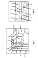
- FIG. 1 shows a directly operated flow control valve according to a first preferred illustrative embodiment of the disclosure, with integrated pressure regulator and pressure regulator piston damping.
- FIG. 2 is an enlarged view of a portion of the flow control valve of FIG. 1 showing a restriction nozzle formed in an end plate and a damping space of the flow control valve.
- FIG. 3 is an enlarged view of another portion of the flow control valve of FIG. 1 showing a measuring orifice and a control orifice of the flow control valve.
- FIG. 1 a preferably directly operated flow control valve according to the preferred illustrative embodiment of the disclosure is represented in cartridge construction.
- the flow control valve according to the disclosure consequently has a cartridge-shaped housing in the form of a sleeve, which on its outer peripheral surface is shaped with a number of axially spaced radial steps 2 .
- the sleeve 1 has on one axial end portion a radially protruding stop ring 4 , which has immediately ahead of it an externally threaded portion 6 to allow the sleeve 1 to be screwed, for example, into a valve block (not shown).
- an axial port P preferably for the connection of a pressure medium feed device (not shown).
- the sleeve 1 is shaped with an inner peripheral groove 8 , which is adjoined, at a small axial distance apart, by a circumferential inner radial shoulder of lesser diameter. Inserted between this radial shoulder 10 and the peripheral groove 8 is an end plate 12 , which is held in an, as far as possible, axially play-free manner by a locking ring 14 (spring ring), which is snapped into the peripheral groove 8 .
- a hollow/sleeve-shaped pressure regulator piston 16 which has an axially extending sliding portion 16 a which has direct sliding contact with the sleeve 1 on the inner wall thereof.
- said pressure regulator piston On that end portion of the pressure regulator piston 16 which is facing the end plate 12 , said pressure regulator piston has a radial outer recess 16 b , which, starting from the sliding portion 16 a , extends as far as that end face of the pressure regulator piston 16 which is facing the end plate 12 .
- a through bore or through hole is shaped, such that the pressure regulator piston 16 , in the region of its outer radial recess 16 a , can be introduced slidingly (centrally) into the end plate 12 .
- an annular space 18 is configured between the pressure regulator piston 16 , the inner sleeve wall and the end plate 12 , which annular space defines a damping chamber 18 (described below).
- at least one further decentralized through bore 20 of predetermined (small) diameter is shaped, which connects the damping chamber to the axial port P and defines a restriction nozzle (further described below).
- the housing sleeve 1 has in an axial middle portion at least one radial through bore 22 , which represents an outlet port A of the valve according to the disclosure.
- the pressure regulator piston 16 here has an axial length which is defined such that the pressure regulator piston 16 , in a first, retracted position (maximally distanced from the end plate 12 ) completely closes off the radial bore 22 in the housing sleeve. In this position, the damping chamber 18 has a maximal spatial volume.
- the inner axial end face of the pressure regulator piston 16 here forms with the housing sleeve 1 , in the region of the radial bore 22 shaped therein, a control orifice R of the valve.
- the pressure regulator piston 16 is also biased by means of a biasing spring 24 in the direction of the end plate 12 for opening of the radial bore 22 in the housing sleeve 1 .
- This biasing spring 24 is inserted for this purpose in the hollow pressure regulator piston 16 and for this purpose is axially supported against a radially inwardly protruding peripheral projection 16 c on the pressure regulator piston 16 .
- An oppositely directed spring seat is further formed by a guide sleeve 26 , which, on an end portion facing away from the end plate 12 , is slidingly inserted in the pressure regulator piston 16 and, at the same time, forms an axial stop for the pressure regulator piston 16 for definition of the first, above-described position of the pressure regulator piston 16 .
- the guide sleeve 26 has on an end portion a radially outer shoulder projection 26 a , which can be brought into operative engagement with the pressure regulator piston 16 for an axial stop. Furthermore, the guide sleeve 26 has at least on its other end portion an outer peripheral surface 26 b , which is in bearing contact against the inner wall of the housing sleeve 1 , preferably forming a seal with said housing sleeve.
- an axially extending circumferential annular space 28 is configured, which is axially delimited by the pressure regulator piston 16 .
- this circumferential annular space 28 between the pressure regulator piston 16 of the housing sleeve 1 and the guide sleeve 26 at least one radial bore 30 in the guide piston 26 emerges at an axial location which cannot be covered over by the pressure regulator piston 16 .
- the guide sleeve 26 is held axially by its inner end portion facing away from the pressure regulator piston 16 by an end stop 32 supported against the housing sleeve 1 .
- an actuating piston 34 in the form of a sleeve is inserted in a sliding and sealing arrangement.
- This actuating piston 34 has in a middle portion a number of radial bores 36 , which form with the at least one radial bore 30 in the guide sleeve 26 an adjustable measuring orifice M.
- the measuring orifice M formed by the respective radial bores 30 , 36 is partially opened in a predetermined manner, whereby the annular space formed by the radially outer periphery of the guide sleeve 26 gains fluid access to the axial port P of the valve.
- the actuating piston 34 is directly operated, i.e. actuated preferably by means of an electromagnetic positioning drive 38 , the actuating piston 34 being additionally biased by means of an adjusting spring 40 into a closing position, represented according to FIG. 1 , in which the measuring orifice M formed by the radial bores 30 , 36 in the actuating piston 34 and the guide sleeve 26 surrounding these is fully closed.
- the pressure regulator piston 16 in an axial portion immediately behind the damping space 18 , is configured with a number of radial bores 42 , which, in dependence on the axial position of the pressure regulator piston 16 with respect to the housing sleeve 1 , can be connected to a further radial bore 44 in the housing sleeve 1 in order thereby to open a bypass circuit T, as is further described below.
- the actuating piston 34 is unactuated, i.e. the preferably electromagnetic positioning drive 38 is in a de-energized state.
- the actuating piston 34 is forced by the adjusting spring 40 into, according to FIG. 1 , a right-hand stop position, in which the measuring orifice M formed between the radial bores 36 in the actuating piston 34 and the at least one radial bore 30 in the guide sleeve 26 surrounding said bores 36 , is fully closed.
- the pressure regulator piston 16 assumes the first axial position, in which the control orifice R formed between the pressure regulator piston 16 and the housing sleeve 1 is fully closed and thus the outlet port A is shut off.
- this switching position furthermore, a connection between the axial port P and the bypass circuit T is opened, so that pressure medium is able to circulate via the flow control valve according to the preferred illustrative embodiment.
- the preferably electromagnetic positioning drive 38 is now actuated, this applies an axial positioning force to the actuating piston 34 , counter to the adjusting spring force, and displaces said actuating piston in the axial direction toward the end plate 12 .
- the measuring orifice M formed between the guide sleeve 26 and the actuating piston 34 is hereupon opened in accordance with the set control value of the actuating piston 34 and thus a restricted access between the axial port P of the valve and the annular space 28 formed between the guide sleeve 26 and the housing sleeve 1 is created.
Landscapes
- Engineering & Computer Science (AREA)
- Power Engineering (AREA)
- Physics & Mathematics (AREA)
- General Physics & Mathematics (AREA)
- Automation & Control Theory (AREA)
- Safety Valves (AREA)
- Control Of Fluid Pressure (AREA)
Applications Claiming Priority (3)
| Application Number | Priority Date | Filing Date | Title |
|---|---|---|---|
| DE102010005524 | 2010-01-23 | ||
| DE102010005524.7 | 2010-01-23 | ||
| DE102010005524A DE102010005524A1 (de) | 2010-01-23 | 2010-01-23 | Stromregelventil mit Dämpfungskammer |
Publications (2)
| Publication Number | Publication Date |
|---|---|
| US20110197979A1 US20110197979A1 (en) | 2011-08-18 |
| US8662097B2 true US8662097B2 (en) | 2014-03-04 |
Family
ID=43646470
Family Applications (1)
| Application Number | Title | Priority Date | Filing Date |
|---|---|---|---|
| US13/010,645 Expired - Fee Related US8662097B2 (en) | 2010-01-23 | 2011-01-20 | Flow control valve with damping chamber |
Country Status (3)
| Country | Link |
|---|---|
| US (1) | US8662097B2 (fr) |
| EP (1) | EP2348376B1 (fr) |
| DE (1) | DE102010005524A1 (fr) |
Cited By (5)
| Publication number | Priority date | Publication date | Assignee | Title |
|---|---|---|---|---|
| US20120049097A1 (en) * | 2009-05-18 | 2012-03-01 | Toyota Jidosha Kabushiki Kaisha | Flow control valve |
| US20120199765A1 (en) * | 2009-10-16 | 2012-08-09 | Philipp Hilzendegen | Valve assembly |
| US20220325709A1 (en) * | 2019-07-11 | 2022-10-13 | Eagle Industry Co., Ltd. | Capacity control valve |
| US20240209874A1 (en) * | 2021-09-29 | 2024-06-27 | Sany Automobile Manufacturing Co. Ltd | Oil drain valve, energy accumulation device, hydraulic system and working machine |
| US12618423B2 (en) * | 2021-09-29 | 2026-05-05 | Sany Autmobile Manufacturing Co. Ltd | Oil drain valve, energy accumulation device, hydraulic system and working machine |
Families Citing this family (7)
| Publication number | Priority date | Publication date | Assignee | Title |
|---|---|---|---|---|
| US9518670B2 (en) * | 2013-03-15 | 2016-12-13 | David E Albrecht | Main stage in-line pressure control cartridge with stepped retainer collar |
| US9091355B2 (en) * | 2013-03-15 | 2015-07-28 | David Albrecht | Main stage in-line pressure control cartridge with optional reverse flow function |
| US9777865B2 (en) * | 2014-04-15 | 2017-10-03 | Fema Corporation Of Michigan | Balanced electronically controlled pressure regulating valve |
| CN107965488A (zh) * | 2017-11-25 | 2018-04-27 | 宁波文泽机电技术开发有限公司 | 一种插装式比例流量阀 |
| CN107965490A (zh) * | 2017-11-25 | 2018-04-27 | 宁波文泽机电技术开发有限公司 | 比例调速阀 |
| CN107763000A (zh) * | 2017-11-25 | 2018-03-06 | 宁波文泽机电技术开发有限公司 | 反比例流量阀 |
| DE102018122437A1 (de) * | 2018-09-13 | 2020-03-19 | Eto Magnetic Gmbh | Proportionalventil |
Citations (12)
| Publication number | Priority date | Publication date | Assignee | Title |
|---|---|---|---|---|
| US4576200A (en) * | 1985-03-26 | 1986-03-18 | Applied Power Inc. | Hydraulic pressure reducing control valve |
| US4630640A (en) * | 1985-06-10 | 1986-12-23 | Sun Hydraulics Corp. | Pressure compensated restrictive flow regulator cartridge |
| US5275207A (en) * | 1991-09-07 | 1994-01-04 | Mercedes-Benz Ag | Multiway valve |
| US5282604A (en) * | 1991-05-30 | 1994-02-01 | Coltec Industries Inc. | Solenoid operated pressure regulating valve |
| US5639066A (en) * | 1995-06-15 | 1997-06-17 | Applied Power Inc. | Bidirectional flow control valve |
| US5836335A (en) * | 1991-08-19 | 1998-11-17 | Fluid Power Industries, Inc. | Proportional pressure control valve |
| US6029703A (en) * | 1998-12-18 | 2000-02-29 | Borg-Warner Automotive, Inc. | Pressure solenoid control valve with flux shunt |
| US20020134443A1 (en) * | 2001-03-26 | 2002-09-26 | Yuzuru Sudani | Solenoid valve |
| US6578606B2 (en) * | 2000-08-03 | 2003-06-17 | Hydraulik-Ring Gmbh | Solenoid valve, in particular, a pressure control valve |
| US6966329B2 (en) | 2003-01-27 | 2005-11-22 | Hydraforce, Inc. | Proportional pilot-operated flow control valve |
| US7104283B2 (en) * | 2003-10-15 | 2006-09-12 | Keihin Corporation | Normally open hydraulic control valve |
| US7717128B2 (en) * | 2005-11-07 | 2010-05-18 | Arpad Matyas Pataki | Pressure balanced three-way valve for motion control |
Family Cites Families (3)
| Publication number | Priority date | Publication date | Assignee | Title |
|---|---|---|---|---|
| US3724485A (en) * | 1971-05-12 | 1973-04-03 | Servo Labs Inc | Flow controller |
| JPS61502988A (ja) * | 1984-07-06 | 1986-12-18 | サークル・シール・コントロールス・インコーポレーテッド | 一定の流量を送り出すための圧力均り合いピストンを有した液体流量調整装置 |
| FR2892486B1 (fr) * | 2005-10-20 | 2009-03-06 | Poclain Hydraulics Ind Soc Par | Valve a ouverture amortie |
-
2010
- 2010-01-23 DE DE102010005524A patent/DE102010005524A1/de not_active Withdrawn
-
2011
- 2011-01-14 EP EP20110000251 patent/EP2348376B1/fr active Active
- 2011-01-20 US US13/010,645 patent/US8662097B2/en not_active Expired - Fee Related
Patent Citations (12)
| Publication number | Priority date | Publication date | Assignee | Title |
|---|---|---|---|---|
| US4576200A (en) * | 1985-03-26 | 1986-03-18 | Applied Power Inc. | Hydraulic pressure reducing control valve |
| US4630640A (en) * | 1985-06-10 | 1986-12-23 | Sun Hydraulics Corp. | Pressure compensated restrictive flow regulator cartridge |
| US5282604A (en) * | 1991-05-30 | 1994-02-01 | Coltec Industries Inc. | Solenoid operated pressure regulating valve |
| US5836335A (en) * | 1991-08-19 | 1998-11-17 | Fluid Power Industries, Inc. | Proportional pressure control valve |
| US5275207A (en) * | 1991-09-07 | 1994-01-04 | Mercedes-Benz Ag | Multiway valve |
| US5639066A (en) * | 1995-06-15 | 1997-06-17 | Applied Power Inc. | Bidirectional flow control valve |
| US6029703A (en) * | 1998-12-18 | 2000-02-29 | Borg-Warner Automotive, Inc. | Pressure solenoid control valve with flux shunt |
| US6578606B2 (en) * | 2000-08-03 | 2003-06-17 | Hydraulik-Ring Gmbh | Solenoid valve, in particular, a pressure control valve |
| US20020134443A1 (en) * | 2001-03-26 | 2002-09-26 | Yuzuru Sudani | Solenoid valve |
| US6966329B2 (en) | 2003-01-27 | 2005-11-22 | Hydraforce, Inc. | Proportional pilot-operated flow control valve |
| US7104283B2 (en) * | 2003-10-15 | 2006-09-12 | Keihin Corporation | Normally open hydraulic control valve |
| US7717128B2 (en) * | 2005-11-07 | 2010-05-18 | Arpad Matyas Pataki | Pressure balanced three-way valve for motion control |
Cited By (7)
| Publication number | Priority date | Publication date | Assignee | Title |
|---|---|---|---|---|
| US20120049097A1 (en) * | 2009-05-18 | 2012-03-01 | Toyota Jidosha Kabushiki Kaisha | Flow control valve |
| US9074702B2 (en) * | 2009-05-18 | 2015-07-07 | Toyota Jidosha Kabushiki Kaisha | Flow control valve |
| US20120199765A1 (en) * | 2009-10-16 | 2012-08-09 | Philipp Hilzendegen | Valve assembly |
| US8973609B2 (en) * | 2009-10-16 | 2015-03-10 | Hydac Fluidtechnik Gmbh | Valve assembly |
| US20220325709A1 (en) * | 2019-07-11 | 2022-10-13 | Eagle Industry Co., Ltd. | Capacity control valve |
| US20240209874A1 (en) * | 2021-09-29 | 2024-06-27 | Sany Automobile Manufacturing Co. Ltd | Oil drain valve, energy accumulation device, hydraulic system and working machine |
| US12618423B2 (en) * | 2021-09-29 | 2026-05-05 | Sany Autmobile Manufacturing Co. Ltd | Oil drain valve, energy accumulation device, hydraulic system and working machine |
Also Published As
| Publication number | Publication date |
|---|---|
| DE102010005524A1 (de) | 2011-07-28 |
| US20110197979A1 (en) | 2011-08-18 |
| EP2348376B1 (fr) | 2013-05-29 |
| EP2348376A1 (fr) | 2011-07-27 |
Similar Documents
| Publication | Publication Date | Title |
|---|---|---|
| US8662097B2 (en) | Flow control valve with damping chamber | |
| US6966329B2 (en) | Proportional pilot-operated flow control valve | |
| US9599183B2 (en) | Damping valve | |
| US9644760B2 (en) | Damping valve | |
| US7341236B2 (en) | Pilot operated valve with a pressure balanced poppet | |
| US20140007964A1 (en) | Proportional pressure-regulating valve | |
| CA2885735C (fr) | Orifice de vanne equilibre pour regulateur de fluide | |
| EP2166423B1 (fr) | Vanne de liquide équilibrée | |
| US8833729B2 (en) | Proportional throttle valve | |
| US10132378B2 (en) | Damping valve | |
| JP2014510242A (ja) | 圧力補償機能を有する電磁比例パイロット作動式ポペット弁 | |
| US8757211B2 (en) | Flow control valve | |
| EP2836774A2 (fr) | Vanne à commande pilote | |
| US9709184B2 (en) | Control valve | |
| CN212564588U (zh) | 一种先导式动态压差平衡阀 | |
| CN111853309A (zh) | 一种先导式动态压差平衡阀 | |
| US3430656A (en) | Positive centering servovalve having movable nozzle block | |
| US7093607B2 (en) | Methods and apparatus for maintaining pressure gain in a servovalve assembly | |
| CN212273180U (zh) | 一种先导式动态压差平衡阀 | |
| US10564652B2 (en) | Valve with flow control and pressure limitation function | |
| US3433266A (en) | Positive centering servovalve having movable spring backup | |
| JP2013079692A (ja) | 流量制御弁 | |
| US20130200281A1 (en) | Flow control valve and method for using the same | |
| CN111853310A (zh) | 一种先导式动态压差平衡阀 |
Legal Events
| Date | Code | Title | Description |
|---|---|---|---|
| AS | Assignment |
Owner name: ROBERT BOSCH GMBH, GERMANY Free format text: ASSIGNMENT OF ASSIGNORS INTEREST;ASSIGNORS:IMHOF, RAINER;SPAHN, WOLFGANG;REEL/FRAME:026048/0401 Effective date: 20110317 |
|
| STCF | Information on status: patent grant |
Free format text: PATENTED CASE |
|
| MAFP | Maintenance fee payment |
Free format text: PAYMENT OF MAINTENANCE FEE, 4TH YEAR, LARGE ENTITY (ORIGINAL EVENT CODE: M1551) Year of fee payment: 4 |
|
| MAFP | Maintenance fee payment |
Free format text: PAYMENT OF MAINTENANCE FEE, 8TH YEAR, LARGE ENTITY (ORIGINAL EVENT CODE: M1552); ENTITY STATUS OF PATENT OWNER: LARGE ENTITY Year of fee payment: 8 |
|
| FEPP | Fee payment procedure |
Free format text: MAINTENANCE FEE REMINDER MAILED (ORIGINAL EVENT CODE: REM.); ENTITY STATUS OF PATENT OWNER: LARGE ENTITY |
|
| LAPS | Lapse for failure to pay maintenance fees |
Free format text: PATENT EXPIRED FOR FAILURE TO PAY MAINTENANCE FEES (ORIGINAL EVENT CODE: EXP.); ENTITY STATUS OF PATENT OWNER: LARGE ENTITY |
|
| STCH | Information on status: patent discontinuation |
Free format text: PATENT EXPIRED DUE TO NONPAYMENT OF MAINTENANCE FEES UNDER 37 CFR 1.362 |