EP2348618A2 - Actuateur - Google Patents
Actuateur Download PDFInfo
- Publication number
- EP2348618A2 EP2348618A2 EP10195587A EP10195587A EP2348618A2 EP 2348618 A2 EP2348618 A2 EP 2348618A2 EP 10195587 A EP10195587 A EP 10195587A EP 10195587 A EP10195587 A EP 10195587A EP 2348618 A2 EP2348618 A2 EP 2348618A2
- Authority
- EP
- European Patent Office
- Prior art keywords
- sensor
- electric motor
- actuator according
- motor
- holding element
- Prior art date
- Legal status (The legal status is an assumption and is not a legal conclusion. Google has not performed a legal analysis and makes no representation as to the accuracy of the status listed.)
- Withdrawn
Links
- 239000011888 foil Substances 0.000 claims abstract description 19
- 239000004020 conductor Substances 0.000 claims description 19
- 230000005540 biological transmission Effects 0.000 description 10
- 238000009434 installation Methods 0.000 description 5
- 238000001514 detection method Methods 0.000 description 4
- 238000004519 manufacturing process Methods 0.000 description 3
- POIUWJQBRNEFGX-XAMSXPGMSA-N cathelicidin Chemical compound C([C@@H](C(=O)N[C@@H](CCCNC(N)=N)C(=O)N[C@@H](CCCCN)C(=O)N[C@@H](CO)C(=O)N[C@@H](CCCCN)C(=O)N[C@@H](CCC(O)=O)C(=O)N[C@@H](CCCCN)C(=O)N[C@@H]([C@@H](C)CC)C(=O)NCC(=O)N[C@@H](CCCCN)C(=O)N[C@@H](CCC(O)=O)C(=O)N[C@@H](CC=1C=CC=CC=1)C(=O)N[C@@H](CCCCN)C(=O)N[C@@H](CCCNC(N)=N)C(=O)N[C@@H]([C@@H](C)CC)C(=O)N[C@@H](C(C)C)C(=O)N[C@@H](CCC(N)=O)C(=O)N[C@@H](CCCNC(N)=N)C(=O)N[C@@H]([C@@H](C)CC)C(=O)N[C@@H](CCCCN)C(=O)N[C@@H](CC(O)=O)C(=O)N[C@@H](CC=1C=CC=CC=1)C(=O)N[C@@H](CC(C)C)C(=O)N[C@@H](CCCNC(N)=N)C(=O)N[C@@H](CC(N)=O)C(=O)N[C@@H](CC(C)C)C(=O)N[C@@H](C(C)C)C(=O)N1[C@@H](CCC1)C(=O)N[C@@H](CCCNC(N)=N)C(=O)N[C@@H]([C@@H](C)O)C(=O)N[C@@H](CCC(O)=O)C(=O)N[C@@H](CO)C(O)=O)NC(=O)[C@H](CC=1C=CC=CC=1)NC(=O)[C@H](CC(O)=O)NC(=O)CNC(=O)[C@H](CC(C)C)NC(=O)[C@@H](N)CC(C)C)C1=CC=CC=C1 POIUWJQBRNEFGX-XAMSXPGMSA-N 0.000 description 2
- 238000005259 measurement Methods 0.000 description 2
- 238000002485 combustion reaction Methods 0.000 description 1
- 238000012790 confirmation Methods 0.000 description 1
- 238000010276 construction Methods 0.000 description 1
- 230000007797 corrosion Effects 0.000 description 1
- 238000005260 corrosion Methods 0.000 description 1
- 230000002950 deficient Effects 0.000 description 1
- 230000000694 effects Effects 0.000 description 1
- 230000002349 favourable effect Effects 0.000 description 1
- 238000007789 sealing Methods 0.000 description 1
Images
Classifications
-
- H—ELECTRICITY
- H02—GENERATION; CONVERSION OR DISTRIBUTION OF ELECTRIC POWER
- H02K—DYNAMO-ELECTRIC MACHINES
- H02K29/00—Motors or generators having non-mechanical commutating devices, e.g. discharge tubes or semiconductor devices
- H02K29/06—Motors or generators having non-mechanical commutating devices, e.g. discharge tubes or semiconductor devices with position sensing devices
-
- H—ELECTRICITY
- H02—GENERATION; CONVERSION OR DISTRIBUTION OF ELECTRIC POWER
- H02K—DYNAMO-ELECTRIC MACHINES
- H02K11/00—Structural association of dynamo-electric machines with electric components or with devices for shielding, monitoring or protection
- H02K11/20—Structural association of dynamo-electric machines with electric components or with devices for shielding, monitoring or protection for measuring, monitoring, testing, protecting or switching
- H02K11/21—Devices for sensing speed or position, or actuated thereby
- H02K11/215—Magnetic effect devices, e.g. Hall-effect or magneto-resistive elements
-
- H—ELECTRICITY
- H02—GENERATION; CONVERSION OR DISTRIBUTION OF ELECTRIC POWER
- H02K—DYNAMO-ELECTRIC MACHINES
- H02K7/00—Arrangements for handling mechanical energy structurally associated with dynamo-electric machines, e.g. structural association with mechanical driving motors or auxiliary dynamo-electric machines
- H02K7/10—Structural association with clutches, brakes, gears, pulleys or mechanical starters
- H02K7/116—Structural association with clutches, brakes, gears, pulleys or mechanical starters with gears
Definitions
- the invention relates to an actuator with an electronically commutated electric motor, a gear unit which is drivable via the electric motor, a first non-contact sensor which detects the rotational position of a rotor of the electric motor for commutation of the electric motor, a second non-contact sensor of the rotational position of an output member of the gear unit detected.
- Such electromotive actuators are used, for example, to drive flaps or valves on an internal combustion engine.
- brush motors were often used to drive, which are increasingly being replaced by electronically commutated motors, since the brush motors are subject to wear of the commutation, increased noise, start-up difficulties due to corrosion of the commutator and high frequency noise due to the mechanical commutator.
- electronically commutated motors have a longer service life, good dynamics and controllability over the entire speed range as well as a high starting torque.
- a reliable rotary bearing feedback of the rotor is required to ensure proper commutation, especially during startup of the electric motor.
- contactless sensors are used, which are often simultaneously as rotary position sensors for the output shaft of the motor and thus for serve subsequent driven parts.
- contactless sensors are used, which are often simultaneously as rotary position sensors for the output shaft of the motor and thus for serve subsequent driven parts.
- the shaft of the rotor is designed as a hollow shaft through which the shaft of the output gear must be passed. Accordingly, two separate bearings are required at the respective axial ends of the electric motor for supporting the two shafts. Furthermore, it is necessary to shield the two magnetic fields of the arranged on the waves permanent magnet against each other, which again additional installation effort and additional space is required. If the shielding is insufficient, the measured values of the rotational position remain inaccurate.
- the construction and assembly of the actuator should be significantly simplified compared to known designs.
- the second non-contact sensor for detecting the rotational position of the driven member via a flexible conductor foil is connected to a circuit board, which is arranged at an axially opposite to the second sensor end of the electric motor and to which the first sensor is attached.
- the first sensor for detecting the rotational position of the rotor directly on the control board, which is arranged on the rear side of the electric motor which is favorable for mounting.
- the magnet for detecting the position of the output member can be arranged in the transmission housing directly opposite to the output member or the output shaft, so that an influence of the magnetic fields is largely excluded.
- the contacting of the second sensor to the control board is nevertheless to be carried out in a simple manner by the flexible conductor foil, so that a single plug connection can be used when connected to an engine control unit.
- the output member has an axis of rotation on which a permanent magnet is mounted, which cooperates with the second sensor.
- a single diametrically magnetized permanent magnet can be used which is precisely aligned with the sensor. This can then also be located on the axis of rotation of the electric motor, so that no effect by rotation of the electric motor changing magnetic field lines on the sensor. This creates an exact rotation angle signal.
- the first sensor is arranged on a rear side of the board, whereby the mounting of the sensor can be carried out prior to installation of the board in the motor housing.
- the Sensor in this way directly opposite the rotor shaft, which in turn allows an accurate measurement of the signals.
- the second sensor and further electronic components for detecting the rotational position of the output member are mounted on the conductor foil. So no additional electrical contacts must be made.
- the second sensor and other electronic components for detecting the rotational position of the drive member may be mounted on a second circuit board which is connected to the conductor foil.
- a second circuit board which is connected to the conductor foil.
- a small board sufficient, which can be easily arranged and fixed in the gear housing. This can be exchanged or checked independently of the printed circuit foil even if errors occur.
- the second sensor is attached to the other electronic components in a holding element.
- a holding element can be adapted to a corresponding receptacle in the housing, whereby the following assembly is simplified.
- the retaining element also serves as protection for the electronic components.
- a guide element at least partially accommodates the conductor film.
- the film can be pushed over the guide member through a correspondingly shaped channel, without any fear of buckling of the film. The assembly is so much easier.
- the guide element is arranged in a channel of a motor housing or a stator of the electric motor which extends from the first axial end of the electric motor to the second axial end of the motor Electric motor leads.
- a continuous channel can be formed according to the guide element and serves to simplify assembly, since the leadership of the film is fixed in the electric motor hereby.
- the holding element is arranged folded in the installed state by 90 ° to the guide element, wherein the guide element and the holding element are rotatably mounted in a plane to each other.
- the guide element can be fastened for example via a film hinge on the holding element.
- the guide element and the holding element can be pushed together during assembly through the channel. In this pushing through, they are in a common plane.
- After passing the holding element it can be rotated or bent by 90 ° to the guide element and pushed in this state into a corresponding recess of the transmission housing.
- the guide element remains in the region of the stator circumference. Accordingly, the assembly is simplified.
- the holding element has a holding part and a lid part, which are fastened to one another in a plane rotatable to each other, being fixed by turning the lid part on the holding part of the second sensor with the electronic components on the holding element.
- the guide element can be made in one piece with the holding part and the cover part, wherein the position of the parts to each other for fastening can be changed by flaps. This facilitates the production.
- the retaining element is inserted into a corresponding opening of a transmission housing of the transmission unit, whereby the position of the sensor is fixed to the permanent magnet. A wrong one Installation is excluded. An attachment is made by pure sliding, without having to use other fasteners.
- an actuator in which the rotational positions of the rotor and a subsequent output member can be detected very accurately, whereby the control of the electric motor to obtain a correct rotational position of the output shaft can be optimized. At the same time, this actuator is easy to assemble and manufacture, reducing production costs.
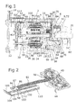
- the in FIG. 1 illustrated actuator according to the invention consists of an electronically commutated electric motor 2, which is arranged in a motor housing 4 and a driven via the electric motor 2 gear unit 6, which is arranged in a transmission housing 8.
- the motor housing 4 surrounds the electric motor 2 substantially over its circumference and is closed at its first axial end 10 with the interposition of a seal 12 of a cover member 14 and at its opposite second axial end 16 of an end cap 18 through which a drive shaft 20 of the electric motor 2 projects into the transmission unit 6.
- This output shaft 20 is rotatably mounted in the motor housing 4 and in the end cap 18 via two ball bearings 22, 24.
- a rotor 26 of the electric motor 2 is arranged in the rotor core 28 magnets 30 are fixed and which cooperates with a stator 32 which consists of a stator 34, on which bobbin 35 are arranged with coils 36 wound thereon.
- the rotor 26 and thus the shaft 20 of the electric motor 2 can be rotated in a known manner.
- these are connected via motor contacts 38 which lead through the coil support 35 to a first board 40, which is arranged at the first axial end 10 of the electric motor 2 perpendicular to the motor axis in an electronics compartment 42 which is closed by the cover member 14 becomes.
- This board 40 is equipped with the necessary electronic components for controlling the electronically commutated electric motor 2 and thus serves as a motor control unit.
- a permanent magnet 48 which is disposed on a drive shaft 20 connected to the magnetic carrier 50 and thus rotates with the drive shaft 20.
- a drive gear 52 is arranged, which meshes with the respective larger gear 54 of a plurality of circumferentially distributed and serving as planetary gears of a planetary gear double gears 56 meshes.
- the double gears 56 are each mounted on an axle 58 which is fixed at its first end to a first housing part 60 of the gear housing 8 and is secured at its second end to a second housing part 62, which in turn via screws 64 on the first housing part 60 during assembly the transmission unit 6 is attached.
- Respectively smaller gears 66 of the double gears 56 are in engagement with a ring gear 68, which in turn is mounted on a serving as output member 70 axis of rotation, which is mounted in a gear housing cover 72 via a sliding bearing 74 and in the second housing part 62 via a sliding bearing 76.
- the gear housing cover 72 is connected with the interposition of a sealing ring 78 with the surrounding the electric motor 2 part of the motor housing 4.
- a lever 80 Serving as the output member 70 axis of rotation has at its outwardly facing end a lever 80, on the example, a subsequent flap can be rotated.
- a permanent magnet 82 is fixed, which cooperates with a second non-contact sensor 84 which is disposed on a second board 86 on which further electronic components 87 are arranged for rotational position detection, via which the signals of the sensor 84 are processed.
- the board 86 is arranged in a receptacle 88 between the first housing part 60 and the second housing part 62 of the gear housing 8, in which the board 86 can be inserted via a corresponding opening 90, that the sensor 84 is disposed exactly opposite to the permanent magnet 82.
- the rotational position of the drive member 70 can be detected directly via the second sensor 84 and the magnet 82. Even with existing game in the transmission, only the position of the drive member is detected.
- the resulting signal can be transmitted via the conductor foil 92 to the circuit board 40 or to the engine control unit.
- a correct signal for commutation of the electric motor 2 is generated by means of the first sensor 46, which rotates in the desired direction until the output signal of the second sensor 84 corresponds to the position to be approached.
- an optimal commutation is still ensured with correct position detection of the drive member.
- FIG. 2 is shown serving as a motor control unit first board 40. It has a contact with the conductor foil 92 via contact elements 96.
- a holding element 98 and a guide element 100 are additionally used, which are connected in the present embodiment by a film hinge 102 such that they are rotatable in a plane to each other.
- the holding element 98 consists of a holding part 104 and a cover part 106, which are also connected to each other via a film hinge 108 and in the same plane as the holding member 98 and the guide member 100 are rotatable relative to each other.
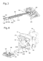
- FIG. 3 shows the arrangement of the components in a subsequent assembly step.
- the conductor film 92 rests on a carrier plate 110 of the guide element 100, where it is clamped under individual projections 112 of the guide element, whereby the conductor film 92 is slidably mounted on the guide member 100.
- the second board 86 rests on the holding part 104 of the holding element 98.
- the cover part 106 has been rotated by 180 ° about the film hinge 108 to the holding part 104, so that the cover part 106 rests on the holding part 104 with the interposition of the circuit board 86.
- On the holding part 104 and the cover part 106 corresponding non-illustrated connecting elements are designed to prevent unwanted loosening.
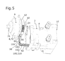
- the conductor foil 92 is pushed with the holding part 104 in advance from the first axial end 10 into the channel 94 of the motor housing 4, as in FIG. 4 is shown. This takes place until the first board 40 is located in the electronics room 42, there by 90 ° to Guide element 100, which is now arranged in the channel 94, is rotated and secured in the electronics compartment 42.
- the channel for receiving the conductor foil in the stator can be formed.
- the detection of the rotor position can optionally take place with appropriate arrangement of the first sensor via the magnetic fields of the rotor.
- Other forms of transmission are just as conceivable as the direct arrangement of the second sensor and the other electronic components directly on the conductor foil.
Landscapes
- Engineering & Computer Science (AREA)
- Power Engineering (AREA)
- Microelectronics & Electronic Packaging (AREA)
- Connection Of Motors, Electrical Generators, Mechanical Devices, And The Like (AREA)
Applications Claiming Priority (1)
| Application Number | Priority Date | Filing Date | Title |
|---|---|---|---|
| DE102010005854.8A DE102010005854B4 (de) | 2010-01-26 | 2010-01-26 | Aktuator |
Publications (1)
| Publication Number | Publication Date |
|---|---|
| EP2348618A2 true EP2348618A2 (fr) | 2011-07-27 |
Family
ID=43754976
Family Applications (1)
| Application Number | Title | Priority Date | Filing Date |
|---|---|---|---|
| EP10195587A Withdrawn EP2348618A2 (fr) | 2010-01-26 | 2010-12-17 | Actuateur |
Country Status (2)
| Country | Link |
|---|---|
| EP (1) | EP2348618A2 (fr) |
| DE (1) | DE102010005854B4 (fr) |
Cited By (2)
| Publication number | Priority date | Publication date | Assignee | Title |
|---|---|---|---|---|
| US20220388333A1 (en) * | 2021-06-02 | 2022-12-08 | Shimano Inc. | Hub assembly for human-powered vehicle |
| US12617485B2 (en) * | 2021-06-02 | 2026-05-05 | Shimano Inc. | Hub assembly for human-powered vehicle |
Families Citing this family (4)
| Publication number | Priority date | Publication date | Assignee | Title |
|---|---|---|---|---|
| DE102012202162A1 (de) | 2011-02-23 | 2012-08-23 | Schaeffler Technologies AG & Co. KG | Hydraulische Einrichtung zur Betätigung einer Kupplung |
| DE102018221859B4 (de) * | 2018-12-17 | 2026-02-26 | Bühler Motor GmbH | Kommutatormotor und Baureihe von Kommutatormotoren |
| DE102019134949B4 (de) | 2019-12-18 | 2025-02-13 | Pierburg Gmbh | Ventilvorrichtung |
| DE102023124159A1 (de) * | 2023-09-07 | 2025-03-13 | Kiekert Aktiengesellschaft | Kraftfahrzeug-Schloss |
Citations (1)
| Publication number | Priority date | Publication date | Assignee | Title |
|---|---|---|---|---|
| EP1489735A2 (fr) | 2003-06-18 | 2004-12-22 | BVR Technologies Company | Procédés et dispositifs pour actionneur électromécanique sans contacts, couplé avec la commutation électronique du motuer et les capteurs de position de sortie |
Family Cites Families (6)
| Publication number | Priority date | Publication date | Assignee | Title |
|---|---|---|---|---|
| JP4186593B2 (ja) | 2002-11-13 | 2008-11-26 | 松下電工株式会社 | Dcブラシレスモータ及びそれを備えたdcポンプ |
| DE102005023202A1 (de) | 2004-10-02 | 2006-09-07 | Schaeffler Kg | Nockenwellenversteller |
| DE102006008416A1 (de) | 2006-02-21 | 2007-08-23 | Zf Friedrichshafen Ag | Elektrischer Antrieb für einen verstellbaren Stabilisator |
| DE102007045815A1 (de) | 2007-09-25 | 2009-04-09 | Magna Powertrain Ag & Co Kg | Getriebeeinheit |
| DE202008008644U1 (de) | 2008-07-01 | 2009-11-19 | Volz Servos Gmbh & Co. Kg | Raumsparender Servomotor |
| DE102008031620A1 (de) | 2008-07-07 | 2010-01-14 | Continental Automotive Gmbh | Verfahren und Vorrichtung zur Ansteuerung von bürstenlosen (EC)-Elektromotoren |
-
2010
- 2010-01-26 DE DE102010005854.8A patent/DE102010005854B4/de active Active
- 2010-12-17 EP EP10195587A patent/EP2348618A2/fr not_active Withdrawn
Patent Citations (1)
| Publication number | Priority date | Publication date | Assignee | Title |
|---|---|---|---|---|
| EP1489735A2 (fr) | 2003-06-18 | 2004-12-22 | BVR Technologies Company | Procédés et dispositifs pour actionneur électromécanique sans contacts, couplé avec la commutation électronique du motuer et les capteurs de position de sortie |
Cited By (2)
| Publication number | Priority date | Publication date | Assignee | Title |
|---|---|---|---|---|
| US20220388333A1 (en) * | 2021-06-02 | 2022-12-08 | Shimano Inc. | Hub assembly for human-powered vehicle |
| US12617485B2 (en) * | 2021-06-02 | 2026-05-05 | Shimano Inc. | Hub assembly for human-powered vehicle |
Also Published As
| Publication number | Publication date |
|---|---|
| DE102010005854B4 (de) | 2023-03-02 |
| DE102010005854A1 (de) | 2011-07-28 |
Similar Documents
| Publication | Publication Date | Title |
|---|---|---|
| DE102007044230B4 (de) | Drehmelder und bürstenfreier Motor | |
| EP3939148B1 (fr) | Dispositif d'entraînement à moteur électrique sans balais | |
| DE102011051264B4 (de) | Motorhalterung und Stellantrieb mit Motor | |
| DE102004059181A1 (de) | Maschine mit integriertem Drehgeber | |
| DE102014201875A1 (de) | Elektromotor mit Haltescheibe und Verfahren zu dessen Montage | |
| DE102015220900A1 (de) | Wischerdirektantrieb | |
| EP0452556A2 (fr) | Capteur pour une direction assistée entraînée par moteur électrique | |
| DE102010005854B4 (de) | Aktuator | |
| EP3583681B1 (fr) | Machine électrique | |
| EP0998658B1 (fr) | Capteur de position magnetique | |
| WO2007065496A1 (fr) | Detecteur d'angle de rotation et système de detection de l'angle de rotation | |
| DE102004056990B4 (de) | Elektrische Maschine, insbesondere bürstenloser Gleichstrommotor, und Verfahren zum Justieren einer Sensoreinheit in einer elektrischen Maschine | |
| DE102010020230A1 (de) | Stelleinheit mit Sensor, Einsteckwerkzeug sowie ein Verfahren zur Positionierung des Sensors | |
| DE102021214471A1 (de) | Rotorwelle und Rotor | |
| DE102015201160B4 (de) | Bürstenloser Gleichstrommotor | |
| EP2934987B1 (fr) | Système de capteurs comportant un dispositif capteur de couple et un dispositif capteur d'angle de direction pour un arbre de direction, lequel présente une partie d'arbre d'entrée, côté volant, et une partie d'arbre de sortie, système d'arbre de direction pour un véhicule automobile, véhicule automobile et procédé de fabrication d'un système d'arbre de direction | |
| DE102019202115A1 (de) | Verfahren zur Einstellung eines Sensorsystems eines Elektromotor sowie Elektromotor | |
| DE10018728A1 (de) | Positionier- und Stellantrieb | |
| WO2014040651A1 (fr) | Pompe électrique pour fluide de refroidissement, à tube à gaine ou à pot à gaine | |
| DE102021118194A1 (de) | Drehmomentsensorvorrichtung und Verfahren zum Zusammenbau einer Drehmomentsensorvorrichtung | |
| WO2020098870A1 (fr) | Machine électrique à capteur de position de rotor et à capteur de température intégré | |
| EP3802185B1 (fr) | Module hybride et système d'entraînement pour un véhicule à moteur et procédé de fabrication d'un tel module hybride | |
| WO2023088764A1 (fr) | Dispositif capteur comprenant une unité capteur de couple et une unité capteur d'angle de braquage pour un véhicule motorisé | |
| WO2024160417A1 (fr) | Dispositif de rotor destiné à un moteur cc pour l'actionnement d'un composant mobile dans un véhicule | |
| DE102023120868A1 (de) | Stator zur Aufnahme eines Rotors eines Elektromotors |
Legal Events
| Date | Code | Title | Description |
|---|---|---|---|
| PUAI | Public reference made under article 153(3) epc to a published international application that has entered the european phase |
Free format text: ORIGINAL CODE: 0009012 |
|
| AK | Designated contracting states |
Kind code of ref document: A2 Designated state(s): AL AT BE BG CH CY CZ DE DK EE ES FI FR GB GR HR HU IE IS IT LI LT LU LV MC MK MT NL NO PL PT RO RS SE SI SK SM TR |
|
| AX | Request for extension of the european patent |
Extension state: BA ME |
|
| STAA | Information on the status of an ep patent application or granted ep patent |
Free format text: STATUS: THE APPLICATION HAS BEEN PUBLISHED |
|
| STAA | Information on the status of an ep patent application or granted ep patent |
Free format text: STATUS: THE APPLICATION IS DEEMED TO BE WITHDRAWN |
|
| 18D | Application deemed to be withdrawn |
Effective date: 20170701 |