EP2351475B1 - Auto-spulenwechsler - Google Patents
Auto-spulenwechsler Download PDFInfo
- Publication number
- EP2351475B1 EP2351475B1 EP09780103A EP09780103A EP2351475B1 EP 2351475 B1 EP2351475 B1 EP 2351475B1 EP 09780103 A EP09780103 A EP 09780103A EP 09780103 A EP09780103 A EP 09780103A EP 2351475 B1 EP2351475 B1 EP 2351475B1
- Authority
- EP
- European Patent Office
- Prior art keywords
- reel
- stopper element
- flexible tape
- tape carrier
- tape
- Prior art date
- Legal status (The legal status is an assumption and is not a legal conclusion. Google has not performed a legal analysis and makes no representation as to the accuracy of the status listed.)
- Not-in-force
Links
- 238000003780 insertion Methods 0.000 claims description 27
- 230000037431 insertion Effects 0.000 claims description 27
- 238000000034 method Methods 0.000 claims description 21
- 230000003287 optical effect Effects 0.000 claims description 5
- 238000001514 detection method Methods 0.000 claims description 4
- 238000006073 displacement reaction Methods 0.000 claims description 3
- 239000004065 semiconductor Substances 0.000 claims 1
- 230000005484 gravity Effects 0.000 description 7
- 238000004519 manufacturing process Methods 0.000 description 6
- 230000008569 process Effects 0.000 description 5
- 230000009471 action Effects 0.000 description 3
- 239000000969 carrier Substances 0.000 description 3
- 238000012360 testing method Methods 0.000 description 3
- 238000005452 bending Methods 0.000 description 2
- 230000015572 biosynthetic process Effects 0.000 description 2
- 239000002390 adhesive tape Substances 0.000 description 1
- 230000008901 benefit Effects 0.000 description 1
- 230000008859 change Effects 0.000 description 1
- 238000012937 correction Methods 0.000 description 1
- 230000009849 deactivation Effects 0.000 description 1
- 230000001419 dependent effect Effects 0.000 description 1
- 238000004806 packaging method and process Methods 0.000 description 1
- 238000003825 pressing Methods 0.000 description 1
- 238000012545 processing Methods 0.000 description 1
- 230000004044 response Effects 0.000 description 1
- 238000003860 storage Methods 0.000 description 1
- 238000012546 transfer Methods 0.000 description 1
- 230000001960 triggered effect Effects 0.000 description 1
- 238000004804 winding Methods 0.000 description 1
Images





Classifications
-
- H—ELECTRICITY
- H05—ELECTRIC TECHNIQUES NOT OTHERWISE PROVIDED FOR
- H05K—PRINTED CIRCUITS; CASINGS OR CONSTRUCTIONAL DETAILS OF ELECTRIC APPARATUS; MANUFACTURE OF ASSEMBLAGES OF ELECTRICAL COMPONENTS
- H05K13/00—Apparatus or processes specially adapted for manufacturing or adjusting assemblages of electric components
- H05K13/02—Feeding of components
- H05K13/021—Loading or unloading of containers
Definitions
- the present invention relates to a device for loading and/or unloading reels with tape-form carriers.
- the device of the invention is suitable for loading and/or unloading electronic components packaged in flexible tapes.
- Automation is a constant goal of many production industries and is of special importance in those manufacturing fields that involve the assembly of a plurality of components, like, for example, the production of electronic equipment.
- An important aspect of industrial automation is the transport and delivery of components to the different production units, or to workstations of a production line.
- Packaging tapes can have indefinite length and may be conveniently coiled in reels for compact storage, protection, transport and interoperation with automatic machinery.
- Coiling and uncoiling operations are often done in a semiautomatic fashion, the reels receiving and delivering the tape carrier being driven in rotation by motors, while the empty and full reels are usually manually placed, and the tape leader is manually inserted in the empty reel.
- Manual operation being slow, costly, and error-prone, there is evidently a need for a device for loading and unloading reels of tape carriers at high speed and with a minimal manual intervention.
- Flexible tapes are often used to carry relatively bulky and large electronic components. Especially when loaded, these tapes are heavy and do not offer high mechanical strength. High speed coiling is delicate in this case, because of the risk of tape failures. This imposes a limit to the speed of known coiling devices and methods, in particular during the delicate phase of insertion of the tape leader into the slot of the reel.
- US5816527 discloses reel tapes for electronic components.
- US4747553 discloses a reel in which a band carrier component is attached to the spool with adhesive tape.
- a first aim of the present invention is to provide a device, and the corresponding method, by which flexible tape carriers can be coiled in reels with less manual operations than in the devices and method that are known in the art.
- a further aim of the present invention is to propose a device, and a corresponding method that are faster in coiling reels of tape carrier than the known devices and methods.
- these aims are achieved by means of the device that is the object of claim 1. More particularly, these aims are achieved by a device that has the features of the preamble of claim 1, characterized by a stopper element, drivable by an actuator in an engagement position in which the stopper elements engages with said reel, resulting in a stop of the rotation of the reel and leaving the reel in a predefined relationship with the tape guides and by a stop detector, providing a stop signal when the rotation of the reel is stopped by the stopper element.
- a device for the automatic coiling and/or uncoiling of a flexible tape on reels comprising: a coiling location where a reel can be rotatably connected to the device; a tape insertion unit, operatively arranged to guide the flexible tape and connect a free end of the flexible tape to a 5 hub of the reel.
- the aims of the invention are achieved by a device as stated above and further comprising: a fist reel magazine for stocking reels to be processed and placed above the coiling location, a second reel magazine for stocking the reels that have been processed placed below the coiling location, the device being operatively arranged to move the reels to be processed from the first magazine towards the coiling location, coil the flexible tape in the reels, and to move the processed reels from the coiling location to the second magazine, the motion of the reels from said first magazine and/or to said second magazine being driven or assisted by gravity.
- the aims of the invention are achieved by a device as above, so arranged that one or more sections of the flexible tape assume the shape of arcs, during a coiling operation.
- the stopper element may engage with a slot in the hub of the reel.
- the stopper element may be further drivable in a rest position in which it is disengaged from the reel, the stopper element in the rest position allowing the insertion of said free end of said flexible tape into said slot.
- the stop detector may be an optical or magnetic or resistive detector arranged for detecting displacement of said stopper element.
- the stop detector may include a switch sensitive to the position of said stopper element.
- the tape guides may be retractable.
- the tape guides may comprise two articulated jaws that can assume an open position, allowing the insertion of the reel in the coiling location and the loading of the tape carrier, in which the articulated jaws are outside a rim of the reel, and a closed position, assisting the connection of the free end of the flexible tape to the hub of the wheel, in which the tape guides enter into the reel.
- the stopper element may be connected to an end of one of said articulated jaws.
- the stopper element may have an interchangeable engaging portion.
- the device may comprise a second stopper element arranged for acting on the side of the reel, said stopper element being actuated by said stop detection signal.
- the second stopper element may be arranged for modifying the angular position of the reel so as to align the reel with the tape when the reel is stopped by the second stopper element.
- the rotation actuator may comprise an electric motor urging in rotation said reel and comprising a rotation detector integrated in said electric motor.
- the motion of the reels to and from said coiling location may be gravity driven.
- the motion of the stopper element between the engagement position and the rest position may be guided as to move the stopper element along a radial direction relative to the reel, in a first portion of motion, and in a slanted direction, in a second portion of motion farther from the hub of the reel than the first portion.
- the device may further comprise a sticker dispenser for stick a free end of the tape in the reel automatically.
- the device may be operatively arranged to:
- a method for coiling a flexible tape carrier on a reel said tape comprising a leading end for engagement in the reel
- the method comprising the steps of: feeding the flexible tape towards the reel; stopping or hindering the advance of said leading end with a first restriction means so as to produce a first slack arc portion in the flexible tape; detecting when the first slack arc portion has reached a determined height; stopping or hindering the advance of one intermediary portion of tape with a second restriction means while feeding the flexible tape further, so a to produce a second slack arc portion of tape; detecting engagement of said leading end into a hub of the reel or alignment of said leading end with a fixation feature of the hub of the reel; releasing the restriction means 161, 162.
- the method may further comprise detecting failed insertion of the tape in the slot, and stopping the advance of said tape in case of failed insertion.
- Failed insertion may be detected by determining the torque or speed or current applied to or by said rotation actuator
- a device for the automatic coiling of flexible tape carrier includes, as shown in figure 1 , a coiling station 80 to which a reel 28 can be connected.
- the reel 28 can be driven in rotation by a suitable rotation actuator, for coiling or uncoiling a carrier tape 60.
- the rotation actuator is preferably, but not necessarily, an electric motor driven by an industrial controller or processor, according to a defined program.
- the rotation actuator is not shown in the figures, for simplicity's sake.
- the reel 28 is connected to the coiling station automatically, or manually, according to the needs.
- the tape carrier 60 is introduced from the right side of the device and is guided, as it will be explained in the following, to the hub 29 of the reel 28.
- the hub 29 presents, in this particular embodiment, a slot 27 that is provided for the insertion of the free end of the carrier tape 60.
- Other manners of connecting the free end of the tape to the wheel are however possible.
- the coiling device of figure 1 also comprises a pair of retractable guides 35, consisting in this case of a pair of articulated jaws. During reel changes and tape loading operations, the guides 35 assume an open configuration, as illustrated in figure 1 , in which they are outside the rim of the reel, in order not to interfere with reel changes and tape loading.
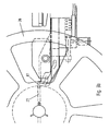
- an empty reel is placed in the coiling location 80 and then the guides 35 are closed, as illustrated in figures 2 and 2a , pivoting the guides 35 with the actuators 53, which can be pneumatic or electric, for example.
- the actuators 53 which can be pneumatic or electric, for example.
- the tips of the guides are close to the surface of the hub 29.
- the guides 35 when closed together, have a free space between them that allows the guided introduction of the free end of the tape carrier 60 to the hub 29.
- the motion of the reel towards the coiling location 80 is driven or assisted by gravity.
- Fig. 2a shows a detail of the loading machine and the lower guide 35, in which the upper guide is not illustrated, to simplify the drawing.
- the lower guide 35 carries, on its end closer to the reel, a pneumatic cylinder or another suitable linear actuator 89 that, when actuated, drives the stopper element 87 against a surface on the hub 29 of the reel.
- the stopping element 87 could engage with another part of the reel, for example the spokes, or a notch in the rim, in order to stop the reel 28 in a predefined angular relationship with the tape guide 35.
- the portion of the stopping element that engages into the slot of the hub or with another part of the reel is preferably interchangeable, so as to allow the loading of different kind of reels with the device and method of the invention.
- the stopping of the rotation of the reel is sensed by a suitable stop detector of the loading device providing a stop detection signal when the rotation of the reel is stopped by the stopping element 87.
- the rotation actuator of the reel is a DC electric motor or a stepper electric motor
- the stop detector is integrated in the motor itself or in the motor controller, for example the stop detector is an electric circuit responsive to the power or current absorbed, generating a stop signal when the rotation of the reel 28 is impeded by the stopping element 87.
- the stop detector may be an optical or magnetic encoder sensitive to the rotation of the reel 28.
- the stop detector includes a switch, sensitive to the position of any part that moves integrally with the stopping element 87 and generating a stop signal when the stopping element 87 is engaged into the slot 27.
- the stop detector needs not be particularly accurate or fast, because the correct alignment of the slot 27 with the guides 35 is determined by the mechanical stopper 87.
- the mechanical stopper 87 is complemented by a second stopping device (not shown) that prevents the rotation of the reel 28 preferably engaging on the reel's side, for example, or alternatively braking the motor's axle.
- the second stopping device is preferably operated in response to the stop signal mentioned above. Its purpose is to limit the force between the mechanical stopper 87 and the slot 27, and to make sure the slot 27 is perfectly aligned with the guides. Auctioning the second stopping device may thus result in a fine correction of the angular position of the reel, which may slightly rotate in the clockwise or anticlockwise direction when the second stopping device is pushed against the reel.
- An additional, independent stop detector detects operation of this additional stooping device.
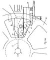
- the reel is immobilized, and the stopper 87 is retracted with the actuator 89, clearing the slot 27, whereby the free end of the tape 60 can be inserted between the guides 35 into the slot 27.
- the motion of the stopper 87 is guided by the pins 93 sliding in the opening 91.
- the stopper 27 moves in a radial direction relative to the reel 28 while, when the stopper has cleared the slot 27 and is farther from the hub, the motion is slanted downwards, in order to provide free passage of the tape carrier 60 into the slot 84.
- the top side of 84 of the stopper is aligned with the bottom side of the slot 27, when the stopper is in the fully retracted position, as shown in fig. 4a , thus providing a guiding surface for the tape carrier.
- a further phase of the loading process illustrated in figure 5
- the free end of the tape 60 is firmly inserted in the slot, and the top guide 35 is lifted.
- the tape is continuously fed from the left and, further advance being impossible, an arc of slack tape (buffer arc) is formed.
- the height of the buffer arc may be sensed by a suitable optical or mechanical sensor, to compensate for speed variations, and to stop the winding process if the buffer becomes too high or to low, thus preventing excessive tension or excessive slack in the tape carrier.
- the length of the tape can be determined during the loading phase by the counter of the taping system.
- the lower guide is retracted, as well as the second stopping element, and the reel 28 is spun until the desired length of carrier tape is loaded.
- the inventive device is arranged to test whether the tape leader has been correctly inserted in the slot 27, and to take appropriate measures, like generating a warning signal and/or stopping the loading operation, in the case of a failed insertion.
- the successful insertion of the tape leader into the slot 27 can be tested, for example, by rotating the reel 28, and at the same time prevent or limit the linear advance of the tape 60, for example pressing it on one of the guides 35 by a suitable actuator. It the tape 60 is correctly connected with the reel hub, rotation of the reel 28 will be hindered. On the other side, if the tape breaks or slips out of the slot 28 for whatever reason, the reel 28 will be able to rotate freely.
- the system senses the torque needed to rotate the reel 28 at a given angular speed, or the rotation speed obtained with a given driving torque, and compares them with reference values to decide whether the tape 60 is satisfactorily connected with the reel 28. This test needs only to be made once shortly after the insertion 8or unsuccessful insertion) of the tape.
- the rotation speed of the reel is sensed with a suitable encoder; failure to insert the tape correctly will result in a higher speed, which can be detected for stopping the device.
- the loading system is equipped with a sticker dispenser, that are automatically operated once the desired length of tape is loaded in the reel 28, to stick his free end to the coil of tape in the reel 28 automatically.
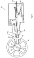
- Figure 7 represents an automatic reel-coiling and changing device according to one aspect of the invention. It includes an upper magazine 70 in which the empty reels 25 waiting to be processed are loaded. The upper magazine is placed above the coiling position 80 in which the reels are mounted on a rotatable shaft 32 for coiling. A tape insertion unit 50 is placed at the same level as the coiling position 80 and is used to automatically guide the tape leading section to the reel and affix it to the hub of the reel, as it will be explained later.
- Figure 10 illustrates, in a simplified schematic way, the automatic reel changing system of the invention.
- the empty reels 25 in the upper magazine 70 are moved by the linear actuator 41 (for example an air cylinder, or a linear motor, or any other equivalent actuator) up to the axis reference 42
- the axis will be used as mechanical reference for the transfer of the roller from the upper magazine to the loading position.
- a linear actuator 42 for example an air cylinder, or a linear motor, or any other equivalent actuator
- a linear actuator 42 will move the empty reel 25 through the opening 71 downwards until they are level with the shaft 32 at the coiling position 80.
- the movement can, in alternative, be guided by additional guiding elements like slides, roll or inclines (not represented) under the action of the gravity until it reaches the desired position.
- the reel will be indexed by reference guides 43, which can be activated by cylinders, motors or any other suitable mechanic actuator.
- the shaft 42 of the reeler will be inserted within the centre of the reel 23.
- the engagement can be.obtained in several ways, for example by a second, non represented linear actuator or, preferably, by a sideways displacement of the shaft 42.
- a motor 39, or any other suitable actuator drives it in rotation in order to fill the reel with the desired amount of flexible tape carrier.
- the full reels 26 are disengaged from the shaft 32 and move downwards, under the action of gravity and of a linear actuator 45 (which could take the form, in different variants of the invention, of an air cylinder, linear motor or any equivalent actuator) into the lower magazine 90.
- the reels could also, in a variant of the invention fall down under the action of gravity only through openings 81. In this case the fall of the reels can be slowed down and guided by appropriate means, when necessary.
- the reel in the coiling position 80 is not rotatably mounted on a shaft, but is moved to a centre-less rotatable support, including one or more free rollers, 5 and one or more driven rollers, interacting with the rim of the reel for supporting it and driving it in rotation (not represented here).
- a straight guide 160 guides the flexible tape 60 towards the hub 29 of the reel 28.
- the part of the guide closer to the hub is composed by a lower sliding guide 128, actuated by the air cylinder 129, and by an upper articulated jaw 125 that, when in operation, as shown in figure 8 , are closed one against the other, defining a channel for guiding the tape to the hub 29 without any deviation.
- the articulated jaw rotates upwards, and the sliding guide 128 moves backwards, as shown in figure 9a , so as to clear the reel and allow its insertion or removal.
- Figure 9a illustrates the beginning of a coiling operation, in which the leading end 61 of the tape 60 is sliding along the guide 160 and is not yet close to the hub 29 of the wheel 28.
- the jaw 125 and the sliding guide 128 are moved one against the other in order to provide a closed channel that guides the strip 60 to the hub 29 without bending it.
- a vacuum is applied to a first restriction device 161 (fig. 3c), in order to stop, or hinder, the forward motion of the flexible strip 60. Since the strip is continuously fed from behind, portion of the strip behind the restriction point 161 lifts from the straight guide 160 forming a slack arc 61, as visible in figure 9c .
- Figure 9d illustrates a further stage of the reel change according to the method of the invention and shows that the arc 61 grows higher because the strip 60 is continuously fed from the right.
- the slack arc 61 is measured by the position sensor 261 that is arranged to detect when the arc 61 has reached a determined height.
- a second restriction device 162 placed upwards with respect to the first restriction device and the feeding direction of the flexible tape 60, is activated to stop or hinder the tape motion, whereby a second arc 62 is formed in the tape 60 before the second restriction device 162.
- the height of the second arc 62 is sensed by position sensor 262.
- position sensors 261 and 262 are both mechanical switches.
- the invention however allows other type of position sensors, for example optical sensors, to sense the height of arcs 61 and 62.
- the structure of restriction devices 161 and 162 can also be adapted and changed, according to the circumstances.
- the first restriction device 161 is a vacuum suction plate, which has the advantage of not damaging or bending the leading end of the tape in any way. It is preferable, for an easy insertion in the slit 291 of the reel's hub 29, that the leading end should be kept very straight.
- the second restriction device 162 is located further upwards, in a position at which small bends in the tape are acceptable, and is a mechanical clamp, operated by a piston, that presses the tape onto the underlying guide 160.
- the insertion unit of the invention preferably includes also a moveable obstacle 165 that is lifted above the straight guide 160 in order to assist the formation of the arc 62.
- the obstacle 165 could also be fixed.
- Figure 9e illustrates some last steps of the insertion process.
- the restriction device 161 and then the restriction device 162 are deactivated, whereby the slack tape in the loops is released and the leading edge of the tape moves rapidly forward, and enters the slit 291 of the reel's hub 29.
- the angular position of the reel 29 is measured by a suitable sensor, and the deactivation of the restriction devices 161 and 162 is timed relative to the passage of the slit 291 in alignment with the leading edge of the tape.
- slotted hubs are almost universally used, it is conceivable that the invention could be used with different kinds of 5 fixation features, for example a hook, a roller, a magnetic connection, or any suitable fixation.
- the coiling of the tape 60 in the reel 29 can proceed normally.
- the jaw 125 and the lower guide 128 are retreated ad this moment, to leave space for the tape inside the reel.
- the speed of rotation of the reel 29 and/or the feeding speed of the tape 60 are preferably controlled so as to maintain a set height in the arcs 61 and 62, as sensed by detectors 261 and 262. In this manner the tape tension is minimal, even at high coiling speed, and is reduced the friction of the tape on the guide.
- Another independent aspect of the invention concerns a device for the automatic coiling and/or uncoiling of a flexible tape 60 on reels 28 comprising: a coiling location 80 where a reel 28 can be rotatably connected to the device; a tape insertion unit 50, operatively arranged to guide the flexible tape 60 and connect a free end of the flexible 60 tape to a hub of the reel 28.
- the devices includes also: a fist reel magazine 70 for stocking reels to be processed 25 and placed above the coiling location 80, a second reel magazine 90 for stocking the reels that have been processed 26 placed below the coiling location 80, the device being operatively arranged to move the reels to be processed 25 from the first magazine 70 towards the coiling location 80, coil the flexible tape 60 in the reels, and to move the processed reels 26 from the coiling location 80 to the second magazine 90, the motion of the reels from said first magazine 70 and/or to said second magazine 90 being driven or assisted by gravity.
- a fist reel magazine 70 for stocking reels to be processed 25 and placed above the coiling location 80
- a second reel magazine 90 for stocking the reels that have been processed 26 placed below the coiling location 80
- the device being operatively arranged to move the reels to be processed 25 from the first magazine 70 towards the coiling location 80, coil the flexible tape 60 in the reels, and to move the processed reels 26 from the coiling location 80 to the second magazine 90
- the above described device further comprising a linear actuator 41, operatively arranged to connect the reels to be processed to the device in the coiling location 80, and/or a linear actuator 41 operatively arranged to move the reels to be processed 25 above a opening 71 in said first reel magazine 70, whereby the reels to be processed 25 move to the opening 71 in their motion towards the coiling 5 location 80.
- the reels that ought to be loaded in the device of the invention are mounted on a rotatable shaft 32 provided to this purpose.
- the reel could be driven by a roller interoperating with an outer rim of the reel to drive the reel in rotation. Centre-less arrangements, in which one or more free rollers to rotatably support the reel in the coiling location are also possible.
- the tape insertion unit of the loading device of the invention contains one linear guide 160 and at least one, preferably two restriction means 161, 162 that can be operated to stop or hinder the advance of at least a section of the flexible tape 60 and induce the formation of one or two arcs 61, 62 behind the restriction means 161, 162, the arc being a self-supported slack portion of the tape 60 lifted from the linear guide 160.
- Said restriction means may consist in a mechanical clamp 162 or a vacuum suction device 161, for example, and position detectors 261, 262 may be arranged to detect the height of at least one arc 61, 62 in the flexible tape 60.
- the present invention therefore provides also a method for coiling a flexible tape carrier 60 on a reel 28, said tape 60 comprising a leading end for engagement in the reel 28, the method comprising the steps of: feeding the flexible tape 60 towards the reel 28; stopping or hindering the advance of said leading end with a first restriction means 161 so as to produce a first slack arc portion 61 in the flexible tape 60; detecting when the first slack arc portion has reached a determined height; stopping or hindering the advance of one intermediary portion of tape with a second restriction means 62 while feeding the flexible tape further, so a to produce a second slack arc portion 62 of tape; detecting engagement of said leading end into a hub 29 of the reel 28 or alignment of said leading end with a fixation feature 291 of the hub 29 of the reel; releasing the restriction means 161, 162.
Landscapes
- Engineering & Computer Science (AREA)
- Manufacturing & Machinery (AREA)
- Microelectronics & Electronic Packaging (AREA)
- Storage Of Web-Like Or Filamentary Materials (AREA)
- Replacement Of Web Rolls (AREA)
- Supply And Installment Of Electrical Components (AREA)
Claims (15)
- Gerät zum automatischen Aufwickeln auf eine und/oder Abwickeln von einer Aufnahmespule (28) eines flexiblen Bandträgers (60) elektronischer Komponenten, das Gerät weist auf:einen Wicklungsort, wo eine Aufnahmespule (28) mit einem Rotationsaktuator verbunden werden kann;Bandführungen (35), operativ angeordnet den flexiblen Bandträger (60) zu führen und ein freies Ende des flexiblen Bandträgers (60) mit einem Spulenkern (29) der Aufnahmespule (28) zu verbinden;ein Stopperelement (87), antreibbar durch einen Aktuator (89) in eine Eingriffsposition in der das Stopperelement in die Aufnahmespule eingreift und die Drehung der Aufnahmespule (28) stoppt, so dass die Aufnahmespule (28) in einem vorherbestimmten Verhältnis zu den Bandführungen steht;ein Stopdetektor, so angeordnet, dass ein Stopdetektionssignal erzeugt wird sobald das Stopperelement in die Aufnahmespule eingreift.
- Das Gerät des vorherigen Anspruchs, wobei das Stopperelement (87) in einen Schlitz (27) in dem Spulenkern (29) der Aufnahmespule (28) eingreift.
- Das Gerät des vorherigen Anspruchs, wobei das Stopperelement (87) in einer Ruheposition, in der es von der Aufnahmespule (28) getrennt ist, weiter antreibbar ist, wobei das Stopperelement in der Ruheposition das Einführen des freien Endes des flexiblen Bandträgers (60) in den Schlitz erlaubt.
- Das Gerät eines der vorherigen Ansprüche, wobei der Stopdetektor ein optischer oder magnetischer oder resistiver Detektor ist, der zum Detektieren der Verschiebung des Stopperelements (87) ausgebildet ist.
- Das Gerät eines der vorherigen Ansprüche, wobei das Stopperelement einen auf die Position des Stopperelements (87) sensitiven Schalter aufweist.
- Das Gerät eines der vorherigen Ansprüche, in dem die Bandführungen (35) abklappbar sind.
- Das Gerät eines der vorherigen Ansprüche, wobei die Bandführungen (35) aus zwei gelenkigen Backen besteht, die eine die Einführung der Aufnahmespule (28) in den Wicklungsort und das Laden des flexiblen Bandträgers ermöglichende offene Position, in der die gelenkigen Backen außerhalb eines Rands der Aufnahmespule (28) sind, und eine die Verbindung des freien Endes des flexiblen Bandträgers (60) mit dem Spulenkern (29) der Aufnahmespule (28) unterstützende geschlossene Position, in der die Bandführungen in die Aufnahmespule (28) eintreten, annehmen können.
- Das Gerät nach dem vorherigen Anspruch, wobei das Stopperelement (87) mit dem einen Ende eines der gelenkigen Backen verbunden ist.
- Das Gerät nach einem der vorherigen Ansprüche, wobei das Stopperelement (87) ein austauschbares Eingriffsteil aufweist.
- Das Gerät nach einem der vorherigen Ansprüche, aufweisend ein zweites Stopperelement angeordnet zur Wirkung auf die Seite der Aufnahmespule, wobei das zweite Stopperelement durch das Stopdetektionssignal ausgelöst wird.
- Das Gerät nach Anspruch 10, wobei das zweite Stopperelement angeordnet ist zur Veränderung der Winkelposition der Aufnahmespule, so dass die Aufnahmespule mit dem flexiblen Bandträger ausgerichtet wird, wenn die Aufnahmespule durch das zweite Stopperelement gestoppt wird.
- Das Gerät nach einem der vorherigen Ansprüche, operativ angeordnet um:eine Aufnahmespule mit dem Wickelort zu verbinden;die Aufnahmespule mit dem Rotationsaktuator zu drehen;das Stopperelement in Eingriff mit einem Schlitz in dem Spulenkern der Aufnahmespule zu fahren;den Eingriff des Stopperelements durch den Stopdetektor;den Rotationsaktuator zum Stillstand bringen;das Stopperelement in die Ruheposition zu fahren;das freie Ende des flexiblen Bandträgers in den Schlitz einzuführen;die Aufnahmespule zu drehen um es mit dem flexiblen Bandträger zu beladen.
- Ein Verfahren des Ladens eines flexiblen Bandträgers (60) für Halbleiterkomponenten in eine Aufnahmespule (28), aufweisend die Schritte:Verbinden einer leeren Aufnahmespule (28) mit einem Rotationsaktuator;Drehen der Aufnahmespule (28) mit dem Rotationsaktuator;Fahren eines Stopperelements (87) in Eingriff mit einem Schlitz (27) in einem Spulenkern (29) der Aufnahmespule, dadurch Stoppen der Rotation der Aufnahmespule (28);Detektieren des Eingriffs des Stopperelements (87) durch einen Stopdetektor;Unbeweglich machen des Rotationsaktuators;Fahren des Stopperelements (87) in eine einen freien Weg für ein freies Ende des flexiblen Bandträgers (60) in den Schlitz (27) freilassende Ruheposition;Einführen des freien Endes des flexiblen Bandträgers (60) in den Schlitz (27);Drehen der Aufnahmespule um sie mit dem flexiblen Bandträger (60) zu beladen.
- Das Verfahren nach Anspruch 13, weiterhin aufweisend Detektieren einer misslungenen Einführung des flexiblen Bandträgers (60) in den Schlitz (27), und Stoppen des Vorlaufs des Bands (60) in dem Fall einer misslungenen Einführung.
- Das Verfahren nach Anspruch 14, wobei die misslungene Einführung durch die Bestimmung des Drehmoments des Rotationsaktuators oder der Geschwindigkeit des Rotationsaktuators oder des an dem Rotationsaktuator angelegtem Stroms.
Priority Applications (1)
| Application Number | Priority Date | Filing Date | Title |
|---|---|---|---|
| EP09780103A EP2351475B1 (de) | 2008-11-17 | 2009-07-02 | Auto-spulenwechsler |
Applications Claiming Priority (4)
| Application Number | Priority Date | Filing Date | Title |
|---|---|---|---|
| EP08169267 | 2008-11-17 | ||
| EP08172524A EP2187723A1 (de) | 2008-11-17 | 2008-12-22 | Autorollenwechsler |
| PCT/EP2009/058356 WO2010054865A1 (en) | 2008-11-17 | 2009-07-02 | Auto reel changer |
| EP09780103A EP2351475B1 (de) | 2008-11-17 | 2009-07-02 | Auto-spulenwechsler |
Publications (2)
| Publication Number | Publication Date |
|---|---|
| EP2351475A1 EP2351475A1 (de) | 2011-08-03 |
| EP2351475B1 true EP2351475B1 (de) | 2013-01-02 |
Family
ID=41479361
Family Applications (2)
| Application Number | Title | Priority Date | Filing Date |
|---|---|---|---|
| EP08172524A Withdrawn EP2187723A1 (de) | 2008-11-17 | 2008-12-22 | Autorollenwechsler |
| EP09780103A Not-in-force EP2351475B1 (de) | 2008-11-17 | 2009-07-02 | Auto-spulenwechsler |
Family Applications Before (1)
| Application Number | Title | Priority Date | Filing Date |
|---|---|---|---|
| EP08172524A Withdrawn EP2187723A1 (de) | 2008-11-17 | 2008-12-22 | Autorollenwechsler |
Country Status (5)
| Country | Link |
|---|---|
| US (1) | US8439292B2 (de) |
| EP (2) | EP2187723A1 (de) |
| CN (1) | CN102232324B (de) |
| MY (1) | MY156506A (de) |
| WO (1) | WO2010054865A1 (de) |
Families Citing this family (14)
| Publication number | Priority date | Publication date | Assignee | Title |
|---|---|---|---|---|
| CA2913122A1 (en) | 2012-09-19 | 2014-03-27 | Umana Family Corporation | Rear discharge mat rolling machine with wrapper |
| SG11201610163QA (en) * | 2014-08-05 | 2017-01-27 | Semiconductor Tech & Instr Inc | Multiple tape reel handling apparatus |
| TWI542525B (zh) * | 2015-06-02 | 2016-07-21 | All Ring Tech Co Ltd | Method and device for transporting tape for electronic component packaging |
| TWI541184B (zh) * | 2015-06-02 | 2016-07-11 | All Ring Tech Co Ltd | Method and device for transporting tape for electronic component packaging |
| KR101886163B1 (ko) * | 2016-09-02 | 2018-08-07 | (주)제이티 | 소자핸들러 및 그에 사용되는 캐리어테이프권취장치 |
| CN106516825B (zh) * | 2016-12-19 | 2018-04-24 | 江阴新基电子设备有限公司 | 载带送料贴胶带装置 |
| US20210020474A1 (en) * | 2018-03-15 | 2021-01-21 | Grand Team Technologies Limited | Automatic output reel changer |
| MY194779A (en) * | 2018-04-10 | 2022-12-15 | Mi Equipment M Sdn Bhd | System and method of replacing reel |
| JP7093837B2 (ja) | 2018-06-27 | 2022-06-30 | ヤマハ発動機株式会社 | 部品供給装置 |
| CN110342308A (zh) * | 2019-06-27 | 2019-10-18 | 江阴新基电子设备有限公司 | 一种自动换盘机收料控制方法 |
| KR102238802B1 (ko) * | 2019-08-26 | 2021-04-12 | (주) 인텍플러스 | 릴 자동 교체시스템 |
| EP4207965A1 (de) * | 2021-12-31 | 2023-07-05 | Nexperia B.V. | Verpackungsspule für elektronische komponente |
| CN116588759B (zh) * | 2022-11-04 | 2024-08-09 | 苏州正齐半导体设备有限公司 | 承载料带插入装置及承载料带插入方法 |
| KR102724259B1 (ko) * | 2024-05-30 | 2024-10-31 | 주식회사 케이티아이시스템 | 표면실장기용 릴 머징 시스템을 위한 릴 머징 유닛 |
Family Cites Families (12)
| Publication number | Priority date | Publication date | Assignee | Title |
|---|---|---|---|---|
| DE1159757B (de) * | 1962-12-08 | 1963-12-19 | Bauer Eugen Gmbh | Selbsttaetige Filmeinfaedelvorrichtung an kinematographischen Aufnahme- oder Wiedergabegeraeten |
| US3270974A (en) * | 1963-10-30 | 1966-09-06 | Eastman Kodak Co | Self-threading camera |
| DE2445998C3 (de) * | 1974-09-26 | 1982-01-14 | Agfa-Gevaert Ag, 5090 Leverkusen | Aufwickelvorrichtung für bandförmiges Material |
| US4604154A (en) * | 1983-11-28 | 1986-08-05 | Owens-Illinois, Inc. | Apparatus and method for guiding plastic labels to a label-wrapping station |
| KR910000613B1 (ko) * | 1986-05-14 | 1991-01-28 | 린테크 가부시끼가이샤 | 전자부품이 장치된 기록용 테이프의 감기방법과 그 장치 |
| JP3002684B2 (ja) * | 1990-07-24 | 2000-01-24 | コニカ株式会社 | フィルム加工装置 |
| EP0543069B1 (de) * | 1991-11-20 | 1996-07-31 | Gretag Imaging Ag | Fotografisches Kopiergerät und Betriebsverfahren |
| DE4204340A1 (de) * | 1992-02-11 | 1993-08-12 | Mannesmann Ag | Aufnahmekassette fuer bahnmaterial, insbesondere fuer eine belichtete filmbahn |
| MY112708A (en) | 1993-09-07 | 2001-08-30 | Lintec Corp | Tape winding apparatus and tape |
| US5632454A (en) * | 1994-03-30 | 1997-05-27 | Noritsu Koki Co., Ltd. | Continuous film take-up apparatus |
| US6123286A (en) * | 1998-12-16 | 2000-09-26 | Kemet Corporation | Apparatus for winding a carrier tape |
| AU2002312383A1 (en) * | 2001-06-07 | 2002-12-16 | Inernational Product Technology Inc. | Multiple output reel taper apparatus |
-
2008
- 2008-12-22 EP EP08172524A patent/EP2187723A1/de not_active Withdrawn
-
2009
- 2009-07-02 CN CN200980145561.8A patent/CN102232324B/zh not_active Expired - Fee Related
- 2009-07-02 WO PCT/EP2009/058356 patent/WO2010054865A1/en not_active Ceased
- 2009-07-02 MY MYPI2011001843A patent/MY156506A/en unknown
- 2009-07-02 EP EP09780103A patent/EP2351475B1/de not_active Not-in-force
-
2011
- 2011-05-03 US US13/099,470 patent/US8439292B2/en not_active Expired - Fee Related
Also Published As
| Publication number | Publication date |
|---|---|
| EP2351475A1 (de) | 2011-08-03 |
| CN102232324A (zh) | 2011-11-02 |
| US8439292B2 (en) | 2013-05-14 |
| CN102232324B (zh) | 2014-07-23 |
| MY156506A (en) | 2016-02-26 |
| WO2010054865A1 (en) | 2010-05-20 |
| EP2187723A1 (de) | 2010-05-19 |
| US20110220755A1 (en) | 2011-09-15 |
Similar Documents
| Publication | Publication Date | Title |
|---|---|---|
| EP2351475B1 (de) | Auto-spulenwechsler | |
| CN107548376B (zh) | 用于输送、提供和更换带有卷绕在其上的扁平和/或薄膜材料的卷筒的方法和设备 | |
| US5341549A (en) | Apparatus for removing yarn remnants | |
| CN106660727B (zh) | 用于操作卷绕在卷盘上的扁平材料和/或薄膜材料的方法和设备 | |
| CN107683249B (zh) | 输送、提供和在包装机中更换带有包装材料的卷筒的方法和设备 | |
| JP6362365B2 (ja) | 綾巻きパッケージを製造する繊維機械の作業部を運転する方法並びに方法を実施する作業部 | |
| KR20230010594A (ko) | 전기 에너지 저장 장치를 제조하기 위한 재료의 릴을 교체하기 위한 시스템 및 관련 방법 | |
| TWI729296B (zh) | 膠帶類送出裝置以及膠帶類送出方法 | |
| EP2072440B1 (de) | Abspulhilfsvorrichtung und Verfahren zum Betreiben einer Abspulhilfsvorrichtung | |
| CN112239104A (zh) | 线缆输送装置、线缆加工系统和将线缆输送给线缆加工机的方法 | |
| EP1655225B1 (de) | Verfahren und Einrichtung zum automatischen Wechseln von Folienrollen einer Maschine für das Umwickeln von Palettenladungen | |
| CN112429564B (zh) | 卷盘自动更换系统 | |
| JP2015506320A5 (de) | ||
| US6533212B1 (en) | Web-splicing apparatus | |
| US12195289B2 (en) | Reel handling machine | |
| JP2001514143A (ja) | ファイバをスプールに巻取る方法および装置 | |
| CN110386494B (zh) | 用于抽出卷轴的装置 | |
| US5971590A (en) | Method for fetching heads from stacks | |
| TWI508636B (zh) | 自動捲式變換器 | |
| EP3187446B1 (de) | Bahnwicklungsvorrichtung | |
| KR100858126B1 (ko) | 스틸 슬리브 폭별 공급장치 | |
| EP4578809A1 (de) | Vakuumbasiertes spannsystem für rohre in einem automatisierten montageverfahren | |
| US20260116697A1 (en) | Vacuum based tensioning system for tubing in an automated assembly process | |
| KR100467799B1 (ko) | 스트립 코일 밴딩머신의 밴드 파손 방지용 클립 장착장치 | |
| JPH06211431A (ja) | 紡糸巻取機のパッケージ排出装置 |
Legal Events
| Date | Code | Title | Description |
|---|---|---|---|
| PUAI | Public reference made under article 153(3) epc to a published international application that has entered the european phase |
Free format text: ORIGINAL CODE: 0009012 |
|
| 17P | Request for examination filed |
Effective date: 20110516 |
|
| AK | Designated contracting states |
Kind code of ref document: A1 Designated state(s): AT BE BG CH CY CZ DE DK EE ES FI FR GB GR HR HU IE IS IT LI LT LU LV MC MK MT NL NO PL PT RO SE SI SK SM TR |
|
| RIN1 | Information on inventor provided before grant (corrected) |
Inventor name: GOH, TOH HAU Inventor name: LAM, KAM KINN Inventor name: CHEE, WAI KOON |
|
| DAX | Request for extension of the european patent (deleted) | ||
| REG | Reference to a national code |
Ref country code: DE Ref legal event code: R079 Ref document number: 602009012539 Country of ref document: DE Free format text: PREVIOUS MAIN CLASS: H05K0013000000 Ipc: H05K0013020000 |
|
| RIC1 | Information provided on ipc code assigned before grant |
Ipc: H05K 13/00 20060101ALI20120307BHEP Ipc: H05K 13/04 20060101ALI20120307BHEP Ipc: H05K 13/02 20060101AFI20120307BHEP |
|
| GRAP | Despatch of communication of intention to grant a patent |
Free format text: ORIGINAL CODE: EPIDOSNIGR1 |
|
| GRAP | Despatch of communication of intention to grant a patent |
Free format text: ORIGINAL CODE: EPIDOSNIGR1 |
|
| GRAS | Grant fee paid |
Free format text: ORIGINAL CODE: EPIDOSNIGR3 |
|
| GRAA | (expected) grant |
Free format text: ORIGINAL CODE: 0009210 |
|
| AK | Designated contracting states |
Kind code of ref document: B1 Designated state(s): AT BE BG CH CY CZ DE DK EE ES FI FR GB GR HR HU IE IS IT LI LT LU LV MC MK MT NL NO PL PT RO SE SI SK SM TR |
|
| REG | Reference to a national code |
Ref country code: GB Ref legal event code: FG4D |
|
| REG | Reference to a national code |
Ref country code: AT Ref legal event code: REF Ref document number: 592198 Country of ref document: AT Kind code of ref document: T Effective date: 20130115 Ref country code: CH Ref legal event code: EP |
|
| REG | Reference to a national code |
Ref country code: IE Ref legal event code: FG4D |
|
| REG | Reference to a national code |
Ref country code: DE Ref legal event code: R096 Ref document number: 602009012539 Country of ref document: DE Effective date: 20130314 |
|
| REG | Reference to a national code |
Ref country code: AT Ref legal event code: MK05 Ref document number: 592198 Country of ref document: AT Kind code of ref document: T Effective date: 20130102 |
|
| REG | Reference to a national code |
Ref country code: NL Ref legal event code: VDEP Effective date: 20130102 |
|
| PG25 | Lapsed in a contracting state [announced via postgrant information from national office to epo] |
Ref country code: SI Free format text: LAPSE BECAUSE OF FAILURE TO SUBMIT A TRANSLATION OF THE DESCRIPTION OR TO PAY THE FEE WITHIN THE PRESCRIBED TIME-LIMIT Effective date: 20130102 |
|
| REG | Reference to a national code |
Ref country code: LT Ref legal event code: MG4D |
|
| PG25 | Lapsed in a contracting state [announced via postgrant information from national office to epo] |
Ref country code: BE Free format text: LAPSE BECAUSE OF FAILURE TO SUBMIT A TRANSLATION OF THE DESCRIPTION OR TO PAY THE FEE WITHIN THE PRESCRIBED TIME-LIMIT Effective date: 20130102 Ref country code: SE Free format text: LAPSE BECAUSE OF FAILURE TO SUBMIT A TRANSLATION OF THE DESCRIPTION OR TO PAY THE FEE WITHIN THE PRESCRIBED TIME-LIMIT Effective date: 20130102 Ref country code: AT Free format text: LAPSE BECAUSE OF FAILURE TO SUBMIT A TRANSLATION OF THE DESCRIPTION OR TO PAY THE FEE WITHIN THE PRESCRIBED TIME-LIMIT Effective date: 20130102 Ref country code: BG Free format text: LAPSE BECAUSE OF FAILURE TO SUBMIT A TRANSLATION OF THE DESCRIPTION OR TO PAY THE FEE WITHIN THE PRESCRIBED TIME-LIMIT Effective date: 20130402 Ref country code: NO Free format text: LAPSE BECAUSE OF FAILURE TO SUBMIT A TRANSLATION OF THE DESCRIPTION OR TO PAY THE FEE WITHIN THE PRESCRIBED TIME-LIMIT Effective date: 20130402 Ref country code: LT Free format text: LAPSE BECAUSE OF FAILURE TO SUBMIT A TRANSLATION OF THE DESCRIPTION OR TO PAY THE FEE WITHIN THE PRESCRIBED TIME-LIMIT Effective date: 20130102 Ref country code: ES Free format text: LAPSE BECAUSE OF FAILURE TO SUBMIT A TRANSLATION OF THE DESCRIPTION OR TO PAY THE FEE WITHIN THE PRESCRIBED TIME-LIMIT Effective date: 20130413 Ref country code: CZ Free format text: LAPSE BECAUSE OF FAILURE TO SUBMIT A TRANSLATION OF THE DESCRIPTION OR TO PAY THE FEE WITHIN THE PRESCRIBED TIME-LIMIT Effective date: 20130102 Ref country code: IS Free format text: LAPSE BECAUSE OF FAILURE TO SUBMIT A TRANSLATION OF THE DESCRIPTION OR TO PAY THE FEE WITHIN THE PRESCRIBED TIME-LIMIT Effective date: 20130502 |
|
| PG25 | Lapsed in a contracting state [announced via postgrant information from national office to epo] |
Ref country code: LV Free format text: LAPSE BECAUSE OF FAILURE TO SUBMIT A TRANSLATION OF THE DESCRIPTION OR TO PAY THE FEE WITHIN THE PRESCRIBED TIME-LIMIT Effective date: 20130102 Ref country code: PL Free format text: LAPSE BECAUSE OF FAILURE TO SUBMIT A TRANSLATION OF THE DESCRIPTION OR TO PAY THE FEE WITHIN THE PRESCRIBED TIME-LIMIT Effective date: 20130102 Ref country code: PT Free format text: LAPSE BECAUSE OF FAILURE TO SUBMIT A TRANSLATION OF THE DESCRIPTION OR TO PAY THE FEE WITHIN THE PRESCRIBED TIME-LIMIT Effective date: 20130502 Ref country code: FI Free format text: LAPSE BECAUSE OF FAILURE TO SUBMIT A TRANSLATION OF THE DESCRIPTION OR TO PAY THE FEE WITHIN THE PRESCRIBED TIME-LIMIT Effective date: 20130102 Ref country code: NL Free format text: LAPSE BECAUSE OF FAILURE TO SUBMIT A TRANSLATION OF THE DESCRIPTION OR TO PAY THE FEE WITHIN THE PRESCRIBED TIME-LIMIT Effective date: 20130102 Ref country code: GR Free format text: LAPSE BECAUSE OF FAILURE TO SUBMIT A TRANSLATION OF THE DESCRIPTION OR TO PAY THE FEE WITHIN THE PRESCRIBED TIME-LIMIT Effective date: 20130403 |
|
| PG25 | Lapsed in a contracting state [announced via postgrant information from national office to epo] |
Ref country code: HR Free format text: LAPSE BECAUSE OF FAILURE TO SUBMIT A TRANSLATION OF THE DESCRIPTION OR TO PAY THE FEE WITHIN THE PRESCRIBED TIME-LIMIT Effective date: 20130102 |
|
| PG25 | Lapsed in a contracting state [announced via postgrant information from national office to epo] |
Ref country code: EE Free format text: LAPSE BECAUSE OF FAILURE TO SUBMIT A TRANSLATION OF THE DESCRIPTION OR TO PAY THE FEE WITHIN THE PRESCRIBED TIME-LIMIT Effective date: 20130102 Ref country code: SK Free format text: LAPSE BECAUSE OF FAILURE TO SUBMIT A TRANSLATION OF THE DESCRIPTION OR TO PAY THE FEE WITHIN THE PRESCRIBED TIME-LIMIT Effective date: 20130102 Ref country code: RO Free format text: LAPSE BECAUSE OF FAILURE TO SUBMIT A TRANSLATION OF THE DESCRIPTION OR TO PAY THE FEE WITHIN THE PRESCRIBED TIME-LIMIT Effective date: 20130102 Ref country code: DK Free format text: LAPSE BECAUSE OF FAILURE TO SUBMIT A TRANSLATION OF THE DESCRIPTION OR TO PAY THE FEE WITHIN THE PRESCRIBED TIME-LIMIT Effective date: 20130102 |
|
| PLBE | No opposition filed within time limit |
Free format text: ORIGINAL CODE: 0009261 |
|
| STAA | Information on the status of an ep patent application or granted ep patent |
Free format text: STATUS: NO OPPOSITION FILED WITHIN TIME LIMIT |
|
| PG25 | Lapsed in a contracting state [announced via postgrant information from national office to epo] |
Ref country code: CY Free format text: LAPSE BECAUSE OF FAILURE TO SUBMIT A TRANSLATION OF THE DESCRIPTION OR TO PAY THE FEE WITHIN THE PRESCRIBED TIME-LIMIT Effective date: 20130102 |
|
| PGFP | Annual fee paid to national office [announced via postgrant information from national office to epo] |
Ref country code: GB Payment date: 20130719 Year of fee payment: 5 |
|
| 26N | No opposition filed |
Effective date: 20131003 |
|
| PG25 | Lapsed in a contracting state [announced via postgrant information from national office to epo] |
Ref country code: IT Free format text: LAPSE BECAUSE OF FAILURE TO SUBMIT A TRANSLATION OF THE DESCRIPTION OR TO PAY THE FEE WITHIN THE PRESCRIBED TIME-LIMIT Effective date: 20130102 |
|
| REG | Reference to a national code |
Ref country code: DE Ref legal event code: R097 Ref document number: 602009012539 Country of ref document: DE Effective date: 20131003 |
|
| PG25 | Lapsed in a contracting state [announced via postgrant information from national office to epo] |
Ref country code: MC Free format text: LAPSE BECAUSE OF FAILURE TO SUBMIT A TRANSLATION OF THE DESCRIPTION OR TO PAY THE FEE WITHIN THE PRESCRIBED TIME-LIMIT Effective date: 20130102 |
|
| REG | Reference to a national code |
Ref country code: CH Ref legal event code: PL |
|
| REG | Reference to a national code |
Ref country code: IE Ref legal event code: MM4A |
|
| PG25 | Lapsed in a contracting state [announced via postgrant information from national office to epo] |
Ref country code: CH Free format text: LAPSE BECAUSE OF NON-PAYMENT OF DUE FEES Effective date: 20130731 Ref country code: LI Free format text: LAPSE BECAUSE OF NON-PAYMENT OF DUE FEES Effective date: 20130731 |
|
| PG25 | Lapsed in a contracting state [announced via postgrant information from national office to epo] |
Ref country code: IE Free format text: LAPSE BECAUSE OF NON-PAYMENT OF DUE FEES Effective date: 20130702 |
|
| GBPC | Gb: european patent ceased through non-payment of renewal fee |
Effective date: 20140702 |
|
| PG25 | Lapsed in a contracting state [announced via postgrant information from national office to epo] |
Ref country code: SM Free format text: LAPSE BECAUSE OF FAILURE TO SUBMIT A TRANSLATION OF THE DESCRIPTION OR TO PAY THE FEE WITHIN THE PRESCRIBED TIME-LIMIT Effective date: 20130102 Ref country code: GB Free format text: LAPSE BECAUSE OF NON-PAYMENT OF DUE FEES Effective date: 20140702 |
|
| REG | Reference to a national code |
Ref country code: FR Ref legal event code: PLFP Year of fee payment: 7 |
|
| PG25 | Lapsed in a contracting state [announced via postgrant information from national office to epo] |
Ref country code: TR Free format text: LAPSE BECAUSE OF FAILURE TO SUBMIT A TRANSLATION OF THE DESCRIPTION OR TO PAY THE FEE WITHIN THE PRESCRIBED TIME-LIMIT Effective date: 20130102 |
|
| PGFP | Annual fee paid to national office [announced via postgrant information from national office to epo] |
Ref country code: MT Payment date: 20130624 Year of fee payment: 5 |
|
| PG25 | Lapsed in a contracting state [announced via postgrant information from national office to epo] |
Ref country code: MK Free format text: LAPSE BECAUSE OF FAILURE TO SUBMIT A TRANSLATION OF THE DESCRIPTION OR TO PAY THE FEE WITHIN THE PRESCRIBED TIME-LIMIT Effective date: 20130102 Ref country code: LU Free format text: LAPSE BECAUSE OF NON-PAYMENT OF DUE FEES Effective date: 20130702 Ref country code: HU Free format text: LAPSE BECAUSE OF FAILURE TO SUBMIT A TRANSLATION OF THE DESCRIPTION OR TO PAY THE FEE WITHIN THE PRESCRIBED TIME-LIMIT; INVALID AB INITIO Effective date: 20090702 |
|
| PGFP | Annual fee paid to national office [announced via postgrant information from national office to epo] |
Ref country code: FR Payment date: 20150626 Year of fee payment: 7 |
|
| PGFP | Annual fee paid to national office [announced via postgrant information from national office to epo] |
Ref country code: DE Payment date: 20150721 Year of fee payment: 7 |
|
| PG25 | Lapsed in a contracting state [announced via postgrant information from national office to epo] |
Ref country code: MT Free format text: LAPSE BECAUSE OF NON-PAYMENT OF DUE FEES Effective date: 20140731 |
|
| REG | Reference to a national code |
Ref country code: DE Ref legal event code: R119 Ref document number: 602009012539 Country of ref document: DE |
|
| PG25 | Lapsed in a contracting state [announced via postgrant information from national office to epo] |
Ref country code: FR Free format text: LAPSE BECAUSE OF NON-PAYMENT OF DUE FEES Effective date: 20160801 Ref country code: DE Free format text: LAPSE BECAUSE OF NON-PAYMENT OF DUE FEES Effective date: 20170201 |
|
| REG | Reference to a national code |
Ref country code: FR Ref legal event code: ST Effective date: 20170331 |
|
| PG25 | Lapsed in a contracting state [announced via postgrant information from national office to epo] |
Ref country code: MT Free format text: LAPSE BECAUSE OF NON-PAYMENT OF DUE FEES Effective date: 20140702 |