EP2352025B1 - Méthode de test de plaquettes sanguines - Google Patents
Méthode de test de plaquettes sanguines Download PDFInfo
- Publication number
- EP2352025B1 EP2352025B1 EP09806724.2A EP09806724A EP2352025B1 EP 2352025 B1 EP2352025 B1 EP 2352025B1 EP 09806724 A EP09806724 A EP 09806724A EP 2352025 B1 EP2352025 B1 EP 2352025B1
- Authority
- EP
- European Patent Office
- Prior art keywords
- blood
- platelet
- capillary
- activating reagent
- anticoagulated
- Prior art date
- Legal status (The legal status is an assumption and is not a legal conclusion. Google has not performed a legal analysis and makes no representation as to the accuracy of the status listed.)
- Active
Links
Images







Classifications
-
- G—PHYSICS
- G01—MEASURING; TESTING
- G01N—INVESTIGATING OR ANALYSING MATERIALS BY DETERMINING THEIR CHEMICAL OR PHYSICAL PROPERTIES
- G01N33/00—Investigating or analysing materials by specific methods not covered by groups G01N1/00 - G01N31/00
- G01N33/48—Biological material, e.g. blood, urine; Haemocytometers
- G01N33/483—Physical analysis of biological material
- G01N33/487—Physical analysis of biological material of liquid biological material
- G01N33/49—Blood
-
- G—PHYSICS
- G01—MEASURING; TESTING
- G01N—INVESTIGATING OR ANALYSING MATERIALS BY DETERMINING THEIR CHEMICAL OR PHYSICAL PROPERTIES
- G01N33/00—Investigating or analysing materials by specific methods not covered by groups G01N1/00 - G01N31/00
- G01N33/48—Biological material, e.g. blood, urine; Haemocytometers
- G01N33/50—Chemical analysis of biological material, e.g. blood, urine; Testing involving biospecific ligand binding methods; Immunological testing
- G01N33/86—Chemical analysis of biological material, e.g. blood, urine; Testing involving biospecific ligand binding methods; Immunological testing involving blood coagulating time or factors, or their receptors
-
- B—PERFORMING OPERATIONS; TRANSPORTING
- B01—PHYSICAL OR CHEMICAL PROCESSES OR APPARATUS IN GENERAL
- B01L—CHEMICAL OR PHYSICAL LABORATORY APPARATUS FOR GENERAL USE
- B01L3/00—Containers or dishes for laboratory use, e.g. laboratory glassware; Droppers
- B01L3/50—Containers for the purpose of retaining a material to be analysed, e.g. test tubes
- B01L3/502—Containers for the purpose of retaining a material to be analysed, e.g. test tubes with fluid transport, e.g. in multi-compartment structures
- B01L3/5027—Containers for the purpose of retaining a material to be analysed, e.g. test tubes with fluid transport, e.g. in multi-compartment structures by integrated microfluidic structures, i.e. dimensions of channels and chambers are such that surface tension forces are important, e.g. lab-on-a-chip
- B01L3/502746—Containers for the purpose of retaining a material to be analysed, e.g. test tubes with fluid transport, e.g. in multi-compartment structures by integrated microfluidic structures, i.e. dimensions of channels and chambers are such that surface tension forces are important, e.g. lab-on-a-chip characterised by the means for controlling flow resistance, e.g. flow controllers, baffles or throttle valves
-
- G—PHYSICS
- G01—MEASURING; TESTING
- G01N—INVESTIGATING OR ANALYSING MATERIALS BY DETERMINING THEIR CHEMICAL OR PHYSICAL PROPERTIES
- G01N33/00—Investigating or analysing materials by specific methods not covered by groups G01N1/00 - G01N31/00
- G01N33/48—Biological material, e.g. blood, urine; Haemocytometers
- G01N33/483—Physical analysis of biological material
- G01N33/487—Physical analysis of biological material of liquid biological material
- G01N33/49—Blood
- G01N33/4905—Determining clotting time of blood
-
- G—PHYSICS
- G01—MEASURING; TESTING
- G01N—INVESTIGATING OR ANALYSING MATERIALS BY DETERMINING THEIR CHEMICAL OR PHYSICAL PROPERTIES
- G01N35/00—Automatic analysis not limited to methods or materials provided for in any single one of groups G01N1/00 - G01N33/00; Handling materials therefor
- G01N35/08—Automatic analysis not limited to methods or materials provided for in any single one of groups G01N1/00 - G01N33/00; Handling materials therefor using a stream of discrete samples flowing along a tube system, e.g. flow injection analysis
-
- B—PERFORMING OPERATIONS; TRANSPORTING
- B01—PHYSICAL OR CHEMICAL PROCESSES OR APPARATUS IN GENERAL
- B01L—CHEMICAL OR PHYSICAL LABORATORY APPARATUS FOR GENERAL USE
- B01L2200/00—Solutions for specific problems relating to chemical or physical laboratory apparatus
- B01L2200/16—Reagents, handling or storing thereof
-
- B—PERFORMING OPERATIONS; TRANSPORTING
- B01—PHYSICAL OR CHEMICAL PROCESSES OR APPARATUS IN GENERAL
- B01L—CHEMICAL OR PHYSICAL LABORATORY APPARATUS FOR GENERAL USE
- B01L2300/00—Additional constructional details
- B01L2300/08—Geometry, shape and general structure
- B01L2300/0809—Geometry, shape and general structure rectangular shaped
- B01L2300/0816—Cards, e.g. flat sample carriers usually with flow in two horizontal directions
-
- B—PERFORMING OPERATIONS; TRANSPORTING
- B01—PHYSICAL OR CHEMICAL PROCESSES OR APPARATUS IN GENERAL
- B01L—CHEMICAL OR PHYSICAL LABORATORY APPARATUS FOR GENERAL USE
- B01L2300/00—Additional constructional details
- B01L2300/08—Geometry, shape and general structure
- B01L2300/0861—Configuration of multiple channels and/or chambers in a single devices
- B01L2300/0877—Flow chambers
-
- B—PERFORMING OPERATIONS; TRANSPORTING
- B01—PHYSICAL OR CHEMICAL PROCESSES OR APPARATUS IN GENERAL
- B01L—CHEMICAL OR PHYSICAL LABORATORY APPARATUS FOR GENERAL USE
- B01L2400/00—Moving or stopping fluids
- B01L2400/04—Moving fluids with specific forces or mechanical means
- B01L2400/0475—Moving fluids with specific forces or mechanical means specific mechanical means and fluid pressure
- B01L2400/0487—Moving fluids with specific forces or mechanical means specific mechanical means and fluid pressure fluid pressure, pneumatics
-
- B—PERFORMING OPERATIONS; TRANSPORTING
- B01—PHYSICAL OR CHEMICAL PROCESSES OR APPARATUS IN GENERAL
- B01L—CHEMICAL OR PHYSICAL LABORATORY APPARATUS FOR GENERAL USE
- B01L2400/00—Moving or stopping fluids
- B01L2400/08—Regulating or influencing the flow resistance
- B01L2400/084—Passive control of flow resistance
- B01L2400/086—Passive control of flow resistance using baffles or other fixed flow obstructions
Definitions
- the present invention relates to a method for measuring platelet function of blood using a small amount of the blood, more particularly, to a method using a microchip for testing platelet function of blood.
- thrombus formation white thrombus
- Platelets directly and indirectly bind to collagen existing under the vascular endothelial cells when a blood vessel is damaged. Under an environment with slow blood flow (under low shear stress), their binding is mainly direct binding via collagen receptors such as GPVI, while under an environment with fast blood flow (under high shear stress), vWF binds to collagen and the GPIb ⁇ receptor of platelets binds to vWF, causing indirect binding of the platelets to collagen. Direct and indirect interactions with collagen activate platelets, and by such stimulation, various platelet-activating substances such as ADP and serotonin are released from dense granules and ⁇ -granules.
- Those released platelet-activating factors activate their own platelets and platelets in their vicinity.
- fibrinogen receptors GPIIb and IIIa are structurally altered to the activated forms, changing the platelets to the high affinity form against fibrinogen.
- fibrinogen which is dimeric, activated platelets are sequentially cross-linked to each other, leading to platelet aggregation.
- Non-patent Document 1 a method to measure activation and the aggregation process of platelets caused by stimulation with a large amount of a platelet-activating reagent
- the platelet activation reaction is induced under an environment which is very different from the physiological platelet activation condition, and, although it has been possible to measure an evident difference in the function such as congenital dysfunction of each receptor, it has been difficult to measure more physiological platelet functions.
- PFA-100 Platinum Function Analyzer: Non-patent Document 2
- PFA-100 Planelet Function Analyzer: Non-patent Document 2
- Patent Document 1 discloses a method for measuring platelet function where blood is allowed to pass through the inside of a capillary and then through the opening of a partitioning member, and the length of time required for obstruction of the opening of the partitioning member by thrombus formation is measured.
- Patent document 2 describes a method for measuring platelet function, which utilizes arachidonic acid at a sufficient concentration to maximally activate platelets.
- Patent Document 3 describes an apparatus and method for monitoring thrombus formation in which anticoagulated blood is flowed through a channel simulating a blood vessel while releasing an anticoagulant treatment or promoting blood coagulation in order to monitor thrombus formation.
- Patent Document 2 fails to teach a method for monitoring platelet aggregation alone.
- platelets In diseases such as sepsis and disseminated intravascular coagulation syndrome (DIC), platelets are in an activated state due to vascular endothelial disorder and thrombus formation, and complexes between platelets and leukocytes and the like are also formed. Further, since platelets are extremely consumed by continuous thrombus formation, a bleeding episode may occur in spite of thrombus formation in vivo.
- DIC disseminated intravascular coagulation syndrome
- platelet function is judged to be promoted (strong) even in cases where platelets are reduced.
- complexes between platelets and leukocytes which are formed by inflammatory response or the like in vivo and largely affect thrombus formation, precipitate together with erythrocytes during centrifugation for preparation of platelet-rich plasma, they are not included in platelet-rich plasma.
- the same concentration of an induction substance is employed for the measurement both in patients having strong platelet function and in patients having weak platelet function, so that it is impossible to appropriately carry out a test to confirm natural aggregation induction under a condition where the induction substance is absent or at a very low concentration or to confirm, in a patient to whom an anti-platelet agent was administered, the pharmacological effect of the agent under a condition where the concentration of the induction substance is very high. Further, even in cases where the obstruction time delayed in measurement with PFA-100, it has been difficult to carry out comparison between the cases where platelet function is weak and where the number of platelets is small but the platelet function is promoted (activated in the living body).
- the present invention was made in view of the above-described circumstances and aims to provide a method which enables efficient and accurate evaluation of platelet function under an environment equivalent to the blood flow, using a small amount of blood.
- the present invention provides a method for testing platelet aggregation, wherein platelet aggregation is tested by subjecting anticoagulated blood to a weak platelet-activation treatment with a platelet-activating reagent, passing the treated anticoagulated blood through a capillary having a platelet-adhesive surface on at least a part of its inner surface, and observing or measuring the behavior of the blood in the capillary to measure platelet aggregation, wherein at least a part of the inside of said capillary has a section comprising walls which extend along the direction of the blood flow in the capillary and divide the width of the capillary into not less than 5 channels, wherein the width of each channel in said section is 10 to 200 ⁇ m, wherein said platelet-adhesive surface is provided in said section of the capillary, and wherein said weak platelet-activation treatment is carried out by mixing the anticoagulated blood with a platelet-activating reagent in an amount with which irreversible platelet
- the anticoagulated blood is preferably a whole blood treated with an anticoagulant selected from citric acid, heparin or hirudin.
- the platelet-adhesive surface is preferably made of collagen coating or glass.
- the platelet-activation treatment is preferably carried out with a platelet-activating reagent
- the platelet-activating reagent is preferably adenosine diphosphate, which is mixed with the anticoagulated blood to a concentration of 0.001 to 5 ⁇ M, or the platelet-activating reagent is preferably arachidonic acid, which is mixed with the anticoagulated blood to a concentration of 0.001 to 1 mM.
- the capillary is preferably formed in a microchip.
- platelet aggregation is preferably tested by a process wherein the anticoagulated blood, subjected to weak platelet-activation treatment, is introduced into the capillary by a pump, and the pressure exerted on the pump by inflow of the blood into the capillary is measured with a pressure sensor.
- the anticoagulated blood is preferably stored in a blood storage section connected to the capillary and the pump, which blood is introduced into the capillary by introduction of a liquid having a specific gravity smaller than the blood into the blood storage section by the pump, and the inflow pressure of the liquid is measured, thereby indirectly measuring the pressure exerted by inflow of the blood into the capillary.
- the anticoagulated blood is preferably stored in a blood storage section connected to the capillary and the pump, which anticoagulated blood is mixed with the platelet-activating reagent in the blood storage section by introduction of the platelet-activating reagent by the pump into the blood storage section, and the blood mixed with the platelet-activating reagent is introduced into the capillary, while measuring the inflow pressure of the platelet-activating reagent, thereby indirectly measuring the pressure exerted by inflow of the blood into the capillary.
- the capillary is connected to the blood storage section, and the anticoagulated blood mixed with the platelet-activating reagent in the blood storage section is allowed to pass through the capillary.
- the platelet-activating reagent is preferably mixed with the anticoagulated blood immediately before the measurement.
- the platelet-activating reagent is mixed with the anticoagulated blood such that the concentration of the platelet-activating reagent in the mixture of the anticoagulated blood and the platelet-activating reagent increases along a linear concentration gradient or a stepwise concentration gradient.
- the mixture of the anticoagulated blood and the platelet-activating reagent is preferably stirred.
- platelet aggregation can be tested by allowing anticoagulated blood to pass through a capillary having a platelet-adhesive surface on at least a part of its inner surface, and observing or measuring the behavior of the blood in the capillary, using as an index activation of platelets by the shear stress caused when the blood passes through the platelet-adhesive surface.
- the anticoagulation treatment can be carried out inexpensively since citric acid, heparin or hirudin is used for the anticoagulation treatment.
- the anticoagulant to be used is a calcium chelator such as citric acid
- measurement of platelet function is carried out more suitably by mixing blood with a platelet-activating reagent and allowing the mixture to pass through the collagen coating.
- an anticoagulant other than a calcium chelator, especially hirudin is used, platelet aggregation occurs more rapidly and strongly on collagen than in cases where the anticoagulation treatment is carried out with citric acid, causing obstruction of the capillary, so that a stable platelet function test is possible even without using a platelet-activating reagent.
- the extent of decrease in platelet function or the effect of the anti-platelet agent can be measured by mixing of a platelet-activating reagent before the measurement.
- the strength of platelet aggregability, the sensitivity to a platelet-inducing substance, the effect of an anti-platelet agent, and the like can be comprehensively measured.
- platelet function can be measured with a substance which is less expensive, since the platelet-adhesive surface is made of glass.
- platelet function can be measured under a more physiological condition and test results reflecting various diseases can be obtained, since the anticoagulated blood is subjected to weak platelet-activation treatment.
- weak platelet-activation treatment can be simply carried out since the weak platelet-activation treatment is carried out by mixing the anticoagulated blood with a platelet-activating reagent in an amount with which irreversible platelet aggregation does not occur, and a combination of platelet activation by a platelet-activating reagent and platelet activation by shear stress on the platelet-adhesive surface allows observation of more physiological platelet activation.
- platelet function can be tested under more physiological conditions and results reflecting various diseases can be obtained since the platelet-activating reagent is adenosine diphosphate which is mixed with the anticoagulated blood to a concentration of 0.001 to 5 ⁇ M.
- platelet function can be tested under more physiological conditions and results reflecting various diseases can be obtained since the platelet-activating reagent is arachidonic acid which is mixed with the anticoagulated blood to a concentration of 0.001 to 1 mM.
- platelet activation by shear stress easily occurs since at least a part of the inside of the capillary has a ing section comprising walls which extend along the direction of the blood flow in the capillary and divide the width of the capillary into not less than 5 channels.
- small platelet aggregates when formed, can increase the internal pressure without being swept away by the blood flow even with fast blood flow and under high shear stress since the width of each channel in the section is 10 to 200 ⁇ m, which allows the channel to provide a scaffold.
- platelet aggregates are easily retained in the section since the platelet-adhesive surface is provided in the section of the capillary.
- a test can be carried out with a small amount of blood since the capillary is formed in a microchip.
- platelet function can be quantitatively measured since the anticoagulated blood is introduced into the capillary by a pump, and the pressure exerted on the pump by inflow of the blood into the capillary is measured with a pressure sensor, thereby testing platelet function.
- the pump is not contaminated with blood since the anticoagulated blood is stored in a blood storage section connected to the capillary and the pump, which blood is introduced into the capillary by introduction of a liquid having a specific gravity smaller than the blood into the blood storage section by the pump, and the inflow pressure of the liquid is measured, thereby indirectly measuring the pressure exerted by inflow of the blood into the capillary.
- a test can be quickly carried out since the anticoagulated blood is stored in a blood storage section connected to the capillary and the pump, which anticoagulated blood is mixed with a platelet-activating reagent in the blood storage section by introduction of the platelet-activating reagent by the pump into the blood storage section, and the blood mixed with the platelet-activating reagent is introduced into the capillary, while measuring the inflow pressure of the platelet-activating reagent, thereby indirectly measuring the pressure exerted by inflow of the blood into the capillary.
- platelet activation by the platelet-activating reagent in a wide range of concentration can be measured and hyperactivity and hypoactivity of platelets can be measured in a single experiment, which is desirable, since the platelet-activating reagent is mixed with the anticoagulated blood such that the concentration of the platelet-activating reagent in the mixture of the anticoagulated blood and the platelet-activating reagent increases along a linear concentration gradient or a stepwise concentration gradient.
- 'blood' includes whole blood and platelet-rich plasma.
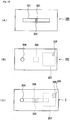
- Fig. 1 is a conceptual diagram showing the first microchip constituting the platelet testing device not according to the invention that can be used in the method for testing platelet aggregation. Explanation will now be made based on Fig. 1 .
- Fig. 1(A) is a plan view showing the first substrate 100 wherein a groove corresponding to the capillary 101 of the microchip 1 is engraved on the surface.
- the cross-sectional shape of this groove is arbitrary and may be rectangular, U-shaped, V-shaped or the like. Since platelet aggregates are fragile, the depth of the groove is preferably not more than 10 to 200 ⁇ m for measuring pressure increase.
- the width of the groove is preferably 10 to 100 ⁇ m.
- a plurality of channel dividing walls 103 extending along the direction of the blood flow are provided to form the channel dividing section 102 which divides the width of the capillary into a plurality of channels.
- the intervals between the channel dividing walls 103 are preferably not more than 200 ⁇ m. With a width of not more than 200 ⁇ m, when a platelet aggregate was formed, the platelet aggregate can increase the internal pressure without being swept away by the blood flow even with fast blood flow and under high shear stress.
- the width of the capillary 101 is preferably divided into not less than 5 channels by the channel dividing walls 103. That is, in case where the width of the channel is divided into not less than 5 channels, obstruction of the respective divided channels are averaged, and therefore data with less variation can be easily obtained.
- the shape of the channel dividing walls 103 is not restricted as long as they can divide the width of the capillary 101 into a plurality of channels.
- Fig. 1(B) is a plan view showing the second substrate 110 on which penetrating holes corresponding to the inlet 104 and the outlet 105 of the microchip 1 are engraved.
- the positions of the penetrating holes corresponding to the inlet 104 and the outlet 105 are the positions corresponding, upon lamination with the first substrate 100, to the first end of the capillary 101 and the second end of the capillary 101, respectively, on the first substrate 100.
- a platelet-adhesive surface 106 is formed. More particularly, as shown in Fig. 1(C) , the collagen or the like is widely applied on the area to be used as the platelet-adhesive surface 106 in consideration of the safety margin.
- the platelet-adhesive surface may also extend over the entire length of the capillary as shown in Fig. 3 (second microchip).
- the material of the second substrate 210 is glass, and the entire length of the second substrate side in the capillary 201 in the microchip 2 works as the platelet-adhesive surface 206.
- a waste liquid reserving section 307 for storing blood waste which has passed through the platelet-adhesive surface 306 may be provided by providing a groove such that it surrounds the position corresponding to the second end of the capillary 301 on the second substrate 310 and covering the groove with the first substrate 300 as shown in Fig. 13 .
- a penetrating hole may be provided in the waste liquid reserving section 307 to provide an air hole 305.
- Fig. 1(C) is a plan view showing the microchip 1 wherein the first substrate 100 and the second substrate 110 are laminated with each other such that the groove on the first substrate 100 and the platelet-adhesive surface of the second substrate 110 are facing inward.
- the wavy line indicates that the capillary 103 exists in the microchip 1.
- the platelet-adhesive surface examples include collagen coating and glass. Among these, collagen is especially preferred since it can be easily obtained and handled, and can provide a model similar to an actual blood vessel.
- the platelet-adhesive surface may also be one containing collagen and tissue thromboplastin. The substance such as collagen is coated on the platelet-adhesive surface 106 with high adhesive strength to avoid being washed away by blood flow.
- the collagen coating can be simply applied with high adhesive strength by, for example, dissolving collagen into an acidic solution and applying the resulting solution to a predetermined position on a substrate such as glass or polystyrene to which hydrophilicity was given, followed by washing and drying the substrate, as described in JP 05-260950 A and Blood. 1995 Apr 1;85(7):1826-35 .
- the coating can be achieved by hydrophilizing the surface of the resin by plasma treatment or the like and then applying a collagen solution to the desired area, followed by air drying or drying under reduced pressure.
- a plastic In cases where a plastic is used as the base material, it can be easily coated with collagen or collagen containing tissue thromboplastin by hydrophilizing its surface by plasma treatment or the like and then applying a collagen solution to the desired area using a dispenser such as a pipette or a syringe.
- a second substrate 110 wherein only the position corresponding to the platelet-adhesive surface 106 is formed with glass and the other area is formed with a plastic, silicone or the like may be used, or, as shown in Fig. 3 , the platelet-adhesive surface 206 may extend over the entire length of the capillary 201 in cases where a glass substrate is used as the second substrate 210 and the second substrate is laminated with a first substrate 200 formed with a plastic, silicone or the like.
- the material of the microchip 1 is preferably a metal, glass, plastic, silicone or the like. In view of usage in blood monitoring (image analysis, especially), a transparent material is preferred. Further, in view of formation of a circuit, a plastic is preferred, and a transparent plastic is especially preferred. In cases where the material is a silicone such as PDMS (polydimethylsiloxane), excellent adhesion is attained between the substrates, so that the first substrate 100 can be laminated with the second substrate 110 even by pressing without using an adhesive or the like for adhesion, but in cases where a high pressure is applied to the inside of the microchip 1 , an adhesive is preferably used.
- PDMS polydimethylsiloxane
- microchips 1 It is also possible to easily and effectively suppress blood coagulation at unexpected sites by using poly(2-methoxyethyl acrylate) (PMEA).
- PMEA poly(2-methoxyethyl acrylate)
- the groove and the hole provided on the substrate of the microchip 1 can be engraved with a cutter or laser beam, and in cases where the material of the microchip 1 is a plastic, they can also be formed by injection molding. Formation by injection molding is preferred since microchips 1 having a constant quality can be prepared efficiently.
- a tube which is not shown is connected, and through the tube, a blood reservoir (blood storage section) 107 and a liquid sending pump 109, which are not shown, are connected.
- a liquid sending pump 109 By injecting the liquid in the connected pump 109 into the reservoir 107, blood in the reservoir is injected to the microchip 1.
- the liquid in the pump is a platelet-activating reagent
- platelets of the anticoagulated blood in the reservoir are activated, and they are further activated due to shear stress when they pass through the platelet-adhesive surface.
- the concentration of the platelet-activating reagent in the reservoir may be continuously increased.
- the platelet-activating reagent is constantly mixed with the blood, which is preferred.
- the liquid in the liquid sending pump may be a liquid having a specific gravity smaller than the blood, such as mineral oil or physiological saline, and the liquid may be introduced into the reservoir preliminarily filled with anticoagulated blood, thereby allowing the blood to be introduced into the capillary.
- the anticoagulated blood with which the reservoir is preliminarily filled is preferably a mixture with a platelet-activating reagent. It is also possible to place a platelet-activating reagent in the reservoir in advance in the dry or liquid state, followed by mixing it with the blood. Further, by increasing the flow rate of the liquid sending pump in a stepwise manner, it is also possible to increase the shear stress in a stepwise manner.
- Examples of the anticoagulant used for anticoagulation treatment to suppress blood coagulation include sodium or potassium citrate; sodium or potassium oxalate; ACD (Acid Citrate Dextrose); and ethylenediaminetetraacetic acid (EDTA) salts.
- Such an anticoagulant may be used as a powder, freeze-dried product or solution such as an aqueous solution.
- 3.2% sodium citrate, which is commonly used, is preferred since it is easily available. In this case, it is preferred to use 1 volume of this anticoagulant for 9 volumes of blood.
- anticoagulants examples include heparin, hirudin, thrombin aptamers and corn-derived trypsin inhibitor ( 1977. J. Biol. Chem 252. 8105 ). More than one anticoagulant may be used. In cases where the anticoagulant employed is hirudin, stronger platelet aggregation, compared to the case of anticoagulation treatment with citric acid, occurs even without treatment with a platelet-activating reagent, so that hirudin is suitable for measurement of shear stress-dependent platelet function. In the case of blood anticoagulated with citric acid, measurement of platelet function dependent on stimulation by a platelet-activating reagent can be accurately carried out, so that citric acid is more suitable for evaluation of an anti-platelet agent and the like.
- Examples of the method to obtain the anticoagulated blood include a method wherein the above-described anticoagulant is preliminarily placed in a syringe or a vacuum blood collection tube, followed by collecting blood therewith, and a method wherein the anticoagulant is quickly added to blood immediately after collection of the blood.
- Examples of the platelet-activating reagent to be mixed with the anticoagulated blood include ADP, collagen, thrombin, arachidonic acid and ristocetin.
- the platelet-activating reagent is mixed with the anticoagulated blood at a concentration at which weak platelet activation occurs.
- the concentration at which weak platelet activation occurs is a concentration at which irreversible platelet aggregation (secondary aggregation of platelets) does not occur under a static state.
- ADP it is 0.001 to 5 ⁇ M
- arachidonic acid it is 0.001 to 1 mM.
- measurement of the extent of the decrease is preferably carried out with addition of a platelet-activating reagent to a concentration higher than these concentrations.
- the mixture of the weak platelet-activating reagent and the anticoagulated blood which has been introduced from the inlet 104 and allowed to pass through the capillary 101 passes through the channel dividing section 102 while causing shear stress and thereby enhancing the activation of platelets, leading to adhesion and accumulation of the platelets on the platelet-adhesive surface.
- By adjusting the flow rate and the microchip and carrying out comparative experiments under high shear stress and low shear stress more detailed evaluation of platelet function, evaluation of the pharmacological effect of an anti-platelet agent, and the like are possible.
- platelet function can be monitored.
- the blood subjected to the monitoring is discharged from the outlet 105 provided at the end of the capillary 101.
- a platelet testing device using the microchip 1 will now be described.
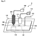
- Fig. 2 is a conceptual diagram of a platelet testing device A, wherein the microchip 1 is constructed with transparent substrates and incorporated into the device. The first device will now be described based on Fig. 2 .
- a reservoir 107 (blood storage section), wherein anticoagulated blood is placed and a stirring bar 108 is contained, is connected in an inverted position, and to the reservoir 107, a liquid sending pump 109 for supplying a platelet-activating reagent is connected via a tube.
- a pressure sensor which is not shown is connected to the liquid sending pump 109.
- the platelet-activating reagent is injected into the reservoir 107, and the platelet-activating reagent and the anticoagulated blood are mixed together by the stirring bar 108 which is driven by a magnetic stirrer 113.
- the ADP concentration may be increased along a concentration gradient from 0 to 0.1 ⁇ M, or the concentration of the induction substance may be increased from 0 to 0.02, 0.04, 0.06, 0.08 and 0.1 ⁇ M in a stepwise manner.
- the anticoagulated blood mixed with the platelet-activating reagent is injected into the capillary 101 of the microchip 1.
- the mixture passes through the capillary 101 and reaches the channel dividing section 102 having a platelet-adhesive surface such as collagen or glass.
- platelet function test By observing activation of platelets (adhesion, aggregation and the like) in the channel dividing section 102 and obstruction of the capillary caused thereby using a camera 111, platelet function can be tested. Alternatively, a more quantitative platelet function test is possible by measuring the pressure in the channel with the pressure sensor connected to the liquid sending pump 109. Further, also by measuring the length of time required for the mixture of the blood and the platelet-activating reagent to pass through the capillary 101 or the amount of the mixture which has passed through the capillary 101, a platelet function test can be carried out.
- the camera 111 is connected to an image analyzer 114, and these enable imaging and the like of the state of platelet activation.
- the combination of visual evaluation by taking images of platelet activation inside the capillary and a quantitative test for platelet activation based on pressure increase is very important in view of overall judgment of the condition of the blood from a patient. For example, in cases where platelets are already activated in vivo but remarkably consumed and reduced in a diseased state such as DIC, the pressure increase and the obstruction are delayed.
- the camera 111 may be movable along the direction of the blood flow in the capillary 101.
- Platelets may be analyzed also by fluorescently labeling platelets with quinacrine or the like.
- the monitoring results may be digitized by monitoring the luminance per unit area due to fluorescence by image analysis, thereby obtaining the monitoring results as data.
- the microchip 1 is placed on a stage-shaped heater 115, and by heating the microchip 1 to 37°C with the heater 115, the monitoring can be carried out under a condition similar to the inside of the body.
- the mixture containing blood which has passed through the channel dividing section 102 is smoothly discharged from the outlet 105 to the outlet duct 112.
- the stirring bar is preferably subjected to anticoagulation treatment.
- the anticoagulation treatment may be coating of the surface of a magnetic material with heparin, polyvinyl lactonamide (PVLA), poly(2-methoxyethyl acrylate) (PMEA) or the like by soaking the magnetic material in a molten resin or formation of the surface of a stirring bar therewith by resin finishing such as in-mold injection molding
- the platelet function testing device is not restricted to the above-described example.
- a mixing section to mix anticoagulated blood and a platelet-activating reagent together is provided in a microchip and the blood and the platelet-activating reagent are mixed together in the microchip, after which the mixture is allowed to flow into the capillary from the mixing section.
- first substrate 100 shown in Fig. 1(A) and a second substrate 110 shown in Fig. 1(B) injection-molded products manufactured by Richell Corporation
- the side of the first substrate 100 wherein the groove corresponding to a capillary 101 opens and the side of the second substrate 110 having a platelet-adhesive surface 106 were bonded together such that these face to each other using a silane coupling agent and thermocompression bonding at 60°C for 16 hours, to provide the microchip 1 shown in Fig. 1(C) .
- the length, depth and width of the channel (capillary) 101 were 20 mm, 50 ⁇ m and 2 mm, respectively.
- each of the holes corresponding to an inlet 104 and an outlet 105 was a penetrating hole having a circular cross section and an inner diameter of 2 mm and a depth of 2 mm.
- 3 mg/ml collagen type I manufactured by Nitta Gelatin Inc. was applied and dried under vacuum to provide the platelet-adhesive surface 106.
- the prepared microchip 1 was placed on a stage-shaped heater 115, and a reservoir 107 was connected to the inlet 104 of the microchip 1.
- a pump109 was connected to the reservoir 107 via a tube, and the pressure exerted on the pump was measured with a pressure sensor which is not shown.
- a cylindrical stirring bar 108 having a diameter of 2 mm and a length of 5 mm, which was prepared by coating an iron cylinder with PMEA, was contained.
- the stirring bar 108 was set such that it can be rotated at 60 to 180 rpm by the magnetic force of a stirrer 113 placed under the heater 115 which was heated to 37°C.
- An outlet duct 112 was connected to the outlet such that the blood after the analysis can be discharged.
- a camera 111 to which an image analyzer 114 was connected was placed above the channel dividing section 102 of the microchip 1, thereby allowing observation of the state of platelet activation in the channel dividing section 102.
- the whole blood subjected to anticoagulation treatment with citric acid was filled in the reservoir 107, and physiological saline was injected from the inlet into the reservoir 107 by the pump 109 connected, thereby extruding the blood from the reservoir 107 and allowing the blood to flow into the microchip 1.
- the stirring bar 108 is contained, and the blood is stirred by the stirring bar 108.
- the flow rate of the pump 109 was 100 ⁇ l/min. for the first 10 seconds, and 3 ⁇ l/min. thereafter.
- Example 2 The experiment was carried out in the same manner as in Example 1 except that the flow rate was 6 ⁇ l/min. instead of 3 ⁇ l/min. (Blood sample A from the same subject as in Example 1 was used.) The changes in the pressure in the pump109 are shown in Fig. 6 . (Discussion) By increasing the flow rate from 3 ⁇ l/min. to 6 ⁇ l/min. using the same sample, shear stress increased, and pressure increase was confirmed.
- Example 2 The experiment was carried out in the same manner as in Example 2 except that 0.5 ⁇ M ADP solution was filled in the pump109 instead of physiological saline. (A blood sample from the same subject A as in Example was used.) The changes in the pressure in the pump109 are shown in Fig. 7 .
- Blood from the subjects A and B were centrifuged at 800 rpm to obtain platelet-rich plasma, and ADP-induced platelet aggregability was measured using an aggregometer (PA-20, Kowa Company, Ltd.). Large aggregates induced by 1 ⁇ M ADP in the blood from the subject A were about a half of those in the blood from the subject B.
- the first substrate 200 shown in Fig. 3A and the second substrate 210 shown in Fig. 3B were laminated with and bonded to each other, to provide the microchip 2 shown in Fig. 3C .
- a substrate made of PDMS Fludware
- the depth of all the channels was 120 ⁇ m; the channel width was 1 mm; the length of the comb was 1 mm; the width of the comb was 50 ⁇ m; and the groove width was 50 ⁇ m.
- the substrate 210 In terms of the substrate 210, a slide glass was used, and penetrating holes corresponding to the inlet and the outlet were provided as in the substrate 110, but, unlike the substrate 110, collagen was not applied since the glass plays a role as a platelet-adhesive surface. That is, the total length of the second substrate side in the capillary 201 works as a platelet-adhesive surface 206.
- the platelet function testing device B shown in Fig. 4 is the same as the platelet function testing device A in Fig. 2 except that the microchip 2 was used instead of the microchip 1 and that it does not have a stirring bar and a stirrer. Since, in the Examples below, anticoagulated blood preliminarily mixed with ADP was placed in the reservoir, a stirring bar and a stirrer were not necessary.
- the microchip 2 shown in Fig. 3 and the platelet function testing device B shown in Fig. 4 were used.
- About 600 ⁇ l of blood anticoagulated with citric acid was filled in a blood reservoir 207.
- a pump 209 was filled with mineral oil, and the pump 209 was connected to the reservoir 207, whose tip was further connected to an inlet 204 in the microchip 2.
- the mineral oil was injected from the pump 209 into the microchip 2 at a flow rate of 20 ⁇ l/min., and the inflow pressure of the mineral oil was measured by a pressure sensor which is not shown.
- first substrate 100 shown in Fig. 1(A) and the second substrate 110 shown in Fig. 1(B) injection-molded products manufactured by Richell Corporation
- the side of the first substrate 100 wherein a groove corresponding to a capillary 101 opens and the side of the second substrate 110 having a platelet-adhesive surface 106 were bonded together such that these face to each other using a silane coupling agent and thermocompression bonding, to provide the microchip 1 shown in Fig. 1(C) .
- the length, depth and width of the channel (capillary) 101 were 20 mm, 50 ⁇ m and 2 mm, respectively.
- each of the holes corresponding to the inlet and the outlet was a penetrating hole having a circular cross section and an inner diameter of 2 mm and a depth of 2 mm.
- about 10 ⁇ l of 3 mg/ml collagen type I manufactured by Nitta Gelatin Inc. was applied and dried under vacuum to provide a platelet-adhesive surface 106.
- the area in which collagen was applied was from 4 mm upstream of the comb to 2 mm downstream of the combs, including the comb.
- the prepared microchip 1 was placed on a heater 215, and a pump209 and a reservoir 207 were connected to the microchip 1 as in Example 8.
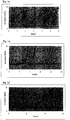
- Example 11 (a), (b) and (c) are shown in Fig. 14(A) .
- the abscissa indicates time, and the ordinate indicates pressure increase due to obstruction in the chip. Pressure increase occurred in the subject D in the order of Examples (a), (b) and (c), that is, in descending order of shear stress.
- Example 11 The same experiment as in Example 11 was carried out also with the subject E. The results are shown in Fig. 14(B) .
- Example 11 The same experiment as in Example 11 was carried out also with the subject F. The results are shown in Fig. 14(C) .
- Platelet aggregability was measured for the subjects D, E and F using a whole-blood aggregometer Multiplate (Dynabyte). Blood was collected using a hirudin blood collection tube, and aggregability induced by 6 ⁇ M ADP was measured. The results were as follows: D, 691 AU/min.; E, 525 AU/min.; and F, 652 AU/min. ADP-induced aggregability was strongest in the subject D, followed by the subject F and the subject E in that order.
- Example 11a An experiment was carried out in the same manner as in Example 11a except that blood was collected with a citric acid blood collection tube and anticoagulated with sodium citrate. In this case, pressure increase was not observed even 10 minutes later.
- Example 15 The results of Examples 15 and 14 are shown in Fig. 15 .
- A indicates the results of Example 15a); B indicates the results of Example 15b; and C indicates the results of Example 14. It can be seen that, in the subject D, pressure increase delayed due to administration of clopidogrel, and that the pressure increase after the administration of clopidogrel was even slower than that of the blood of the subject E.
- Example 16 The experiments a to f in Example 16 were carried out for the subject G 6 hours after dosing with 100 mg of aspirin.
- Example 16 to 18 The results of Example 16 to 18 are shown in Figs. 16 to 21 .
- Example 19 An experiment was carried out in the same manner as in Example 19 except that mineral oil was injected from the pump 209 into the reservoir at a flow rate of 200 ⁇ l/min. for the first 5 seconds, and 7 ⁇ l/min. thereafter, thereby injecting the blood in the reservoir into the microchip 1 at the same flow rates, while measuring the inflow pressure of the mineral oil.
- Fig. 22 shows the inhibitory effect of ReoPro at a flow rate of 20 ⁇ l/min.
- Fig. 23 shows the inhibitory effect of ReoPro at a flow rate of 7 ⁇ l/min.
- Example 22 The results of Example 22 are shown in Fig. 24 and Fig. 25 .
- Fig. 24 shows the inhibitory effect of OS-1 at a flow rate of 20 ⁇ l/min.
- Fig. 25 shows the inhibitory effect of OS-1 at a flow rate of 7 ⁇ l/min.
- GPIIb/IIIa binds mainly to fibrinogen and is involved in platelet aggregation
- GPIb is a receptor which binds to vWF and is involved in the platelet adhesion reaction under high shear stress.
- OS-1 which suppresses the platelet adhesion reaction, showed a strong anti-platelet action under high shear stress, while ReoPro showed a rather strong anti-platelet effect under low shear stress.
- A, B platelet monitoring device; 1, 2, 3: microchip; 100, 200, 300: first substrate; 101, 201, 301: capillary; 102, 202, 302: channel dividing section; 103, 203, 303: channel dividing walls; 104, 204, 304: inlet; 105, 205: outlet; 106, 206, 306: platelet-adhesive surface; 107, 207: reservoir; 108: stirring bar; 109, 209: pump; 110, 210: second substrate; 111, 211: camera; 112, 212: outlet duct; 113: stirrer; 114, 214: image analyzer; 115, 215: heater; 305: air hole; 307: waste liquid reserving section; 308: blood absorbing material
Landscapes
- Health & Medical Sciences (AREA)
- Life Sciences & Earth Sciences (AREA)
- Engineering & Computer Science (AREA)
- Chemical & Material Sciences (AREA)
- Hematology (AREA)
- Biomedical Technology (AREA)
- Immunology (AREA)
- Physics & Mathematics (AREA)
- Molecular Biology (AREA)
- Urology & Nephrology (AREA)
- Analytical Chemistry (AREA)
- General Health & Medical Sciences (AREA)
- Pathology (AREA)
- Biochemistry (AREA)
- General Physics & Mathematics (AREA)
- Medicinal Chemistry (AREA)
- Food Science & Technology (AREA)
- Biotechnology (AREA)
- Cell Biology (AREA)
- Microbiology (AREA)
- Ecology (AREA)
- Biophysics (AREA)
- Dispersion Chemistry (AREA)
- Clinical Laboratory Science (AREA)
- Chemical Kinetics & Catalysis (AREA)
- Investigating Or Analysing Biological Materials (AREA)
Claims (10)
- Procédé pour tester l'agrégation des plaquettes, comprenant l'exposition d'un sang traité par anticoagulation à un traitement d'activation des plaquettes faible avec un réactif activant les plaquettes, le passage du sang traité par anticoagulation traité à travers un capillaire ayant une surface adhésive pour les plaquettes sur au moins une partie de sa surface interne, et l'observation ou la mesure du comportement du sang dans le capillaire pour tester l'agrégation des plaquettes,
où au moins une partie de l'intérieur dudit capillaire a une section comprenant des parois qui s'étendent dans la direction de l'écoulement du sang dans le capillaire et divisent la largeur du capillaire en pas moins de 5 canaux, où la largeur de chaque canal dans ladite section est 10 à 200 µm,
où ladite surface adhésive pour les plaquettes est prévue dans ladite section du capillaire, et
où ledit traitement d'activation des plaquettes faible est réalisé par mélange du sang traité par anticoagulation avec un réactif activant les plaquettes en une quantité avec laquelle une agrégation des plaquettes irréversible ne se produit pas. - Procédé selon la revendication 1, où ledit sang traité par anticoagulation est un sang total traité avec un anticoagulant choisi parmi l'acide citrique, l'héparine et l'hirudine.
- Procédé selon la revendication 1 ou 2, où ladite surface adhésive pour les plaquettes est faite d'un revêtement de collagène ou faite de verre.
- Procédé selon la revendication 1, où ledit réactif activant les plaquettes est l'adénosine diphosphate, qui est mélangé avec le sang traité par anticoagulation jusqu'à une concentration de 0,001 à 5 µM ou ledit réactif activant les plaquettes est l'acide arachidonique, qui est mélangé avec le sang traité par anticoagulation jusqu'à une concentration de 0,001 à 1 mM.
- Procédé selon l'une quelconque des revendications 1 à 4, où ledit capillaire est formé dans une micropuce.
- Procédé selon l'une quelconque des revendications 1 à 5, où ledit sang traité par anticoagulation est introduit dans le capillaire par une pompe, et la pression exercée sur la pompe par l'entrée du sang dans le capillaire est mesurée avec un capteur de pression, testant ainsi l'agrégation des plaquettes.
- Procédé selon la revendication 6, où ledit sang traité par anticoagulation est stocké dans une section de stockage de sang reliée au capillaire et à la pompe, lequel sang est introduit dans le capillaire par introduction d'un liquide ayant une masse volumique inférieure au sang dans la section de stockage de sang par la pompe, et la pression d'entrée du liquide est mesurée, mesurant ainsi indirectement la pression exercée par l'entrée du sang dans le capillaire.
- Procédé selon la revendication 6, où ledit sang traité par anticoagulation est stocké dans une section de stockage de sang reliée au capillaire et à la pompe, lequel sang traité par anticoagulation est mélangé avec le réactif activant les plaquettes dans la section de stockage de sang par introduction du réactif activant les plaquettes par ladite pompe dans la section de stockage de sang, et le sang mélangé avec le réactif activant les plaquettes est introduit dans le capillaire, tout en mesurant la pression d'entrée du réactif activant les plaquettes, mesurant ainsi indirectement la pression exercée par l'entrée du sang dans le capillaire.
- Procédé selon la revendication 8, où ledit réactif activant les plaquettes est mélangé avec le sang traité par anticoagulation de sorte que la concentration du réactif activant les plaquettes dans le mélange du sang traité par anticoagulation et du réactif activant les plaquettes augmente suivant un gradient de concentration linéaire ou un gradient de concentration par pas.
- Procédé selon la revendication 8 ou 9, où le mélange du sang traité par anticoagulation et du réactif activant les plaquettes est agité.
Applications Claiming Priority (3)
| Application Number | Priority Date | Filing Date | Title |
|---|---|---|---|
| JP2008207389 | 2008-08-11 | ||
| JP2008330222 | 2008-12-25 | ||
| PCT/JP2009/064202 WO2010018833A1 (fr) | 2008-08-11 | 2009-08-11 | Méthode et dispositif de test de plaquettes sanguines |
Publications (3)
| Publication Number | Publication Date |
|---|---|
| EP2352025A1 EP2352025A1 (fr) | 2011-08-03 |
| EP2352025A4 EP2352025A4 (fr) | 2013-08-07 |
| EP2352025B1 true EP2352025B1 (fr) | 2020-07-15 |
Family
ID=41668977
Family Applications (1)
| Application Number | Title | Priority Date | Filing Date |
|---|---|---|---|
| EP09806724.2A Active EP2352025B1 (fr) | 2008-08-11 | 2009-08-11 | Méthode de test de plaquettes sanguines |
Country Status (11)
| Country | Link |
|---|---|
| US (2) | US20110151500A1 (fr) |
| EP (1) | EP2352025B1 (fr) |
| JP (1) | JP5421918B2 (fr) |
| KR (1) | KR101652780B1 (fr) |
| CN (1) | CN102150042B (fr) |
| AU (1) | AU2009280612B2 (fr) |
| BR (1) | BRPI0918025B8 (fr) |
| CA (1) | CA2733361C (fr) |
| ES (1) | ES2808503T3 (fr) |
| RU (1) | RU2543652C2 (fr) |
| WO (1) | WO2010018833A1 (fr) |
Families Citing this family (31)
| Publication number | Priority date | Publication date | Assignee | Title |
|---|---|---|---|---|
| JP5752055B2 (ja) * | 2010-02-10 | 2015-07-22 | 藤森工業株式会社 | 血小板検査用マイクロチップ及びそれを用いた血小板検査装置 |
| JP2012008044A (ja) * | 2010-06-25 | 2012-01-12 | Yamaguchi Univ | 血小板活性化能の測定方法および抗血小板薬の評価方法 |
| KR101283043B1 (ko) | 2011-06-10 | 2013-07-05 | 현대자동차주식회사 | 차량용 디스크 로터 조립체 |
| KR101193566B1 (ko) | 2011-08-10 | 2012-10-22 | 고려대학교 산학협력단 | 마이크로칩 기반 혈소판 복합기능 검사 장치 |
| US9140684B2 (en) | 2011-10-27 | 2015-09-22 | University Of Washington Through Its Center For Commercialization | Device to expose cells to fluid shear forces and associated systems and methods |
| CN103323296A (zh) * | 2012-03-23 | 2013-09-25 | 南京柯伦迪检测技术有限公司 | 一种用于血小板功能检测的抗凝剂配合使用方法 |
| AU2013260125A1 (en) * | 2012-05-10 | 2014-11-20 | University Of Washington Through Its Center For Commercialization | Microfluidic devices for measuring platelet coagulation, and associated systems and methods |
| JP6322144B2 (ja) * | 2012-12-20 | 2018-05-09 | 藤森工業株式会社 | 血小板凝集能の総合的評価方法 |
| KR101481240B1 (ko) * | 2012-12-27 | 2015-01-19 | 고려대학교 산학협력단 | 마이크로 유동칩 기반 혈소판 기능 및 약물반응 검사 장치 및 방법 |
| KR101497193B1 (ko) * | 2012-12-31 | 2015-03-03 | 고려대학교 산학협력단 | 원심력 미세유동 기반 혈소판 복합기능 및 약물반응 검사 장치 및 방법 |
| US9176112B2 (en) * | 2012-12-31 | 2015-11-03 | Beckman Coulter, Inc. | Systems and methods for platelet count with clump adjustment |
| US10272428B2 (en) | 2013-04-30 | 2019-04-30 | Hewlett-Packard Development Company, L.P. | Microfluidic sensing device and system |
| JP2016524156A (ja) * | 2013-06-26 | 2016-08-12 | ユニヴァーシティ オブ ワシントン センター フォー コマーシャライゼーション | 個別化された凝集測定のための流体素子 |
| US10788502B2 (en) | 2014-02-06 | 2020-09-29 | Fujimori Kogyo Co., Ltd. | Erythrocyte sedimentation inhibitor |
| JP6596768B2 (ja) * | 2014-04-08 | 2019-10-30 | 藤森工業株式会社 | 血液性状検査用マイクロチップおよび血液性状検査用装置 |
| WO2015167047A1 (fr) * | 2014-04-29 | 2015-11-05 | 고려대학교 산학협력단 | Puce destinée à tester des plaquettes et dispositif de test de plaquettes l'utilisant |
| JP2018506718A (ja) * | 2015-01-30 | 2018-03-08 | ヒューレット−パッカード デベロップメント カンパニー エル.ピー.Hewlett‐Packard Development Company, L.P. | 診断装置 |
| WO2016122572A1 (fr) * | 2015-01-30 | 2016-08-04 | Hewlett-Packard Development Company, L.P. | Puce de diagnostic |
| EP3237112B1 (fr) * | 2015-01-30 | 2021-05-26 | Hewlett-Packard Development Company, L.P. | Réservoirs microfluidiques à évent |
| ES2833357T3 (es) * | 2015-11-02 | 2021-06-15 | Megakaryon Corp | Procedimiento de preparación de plaquetas con un dispositivo de agitación recíproca |
| WO2017119508A1 (fr) | 2016-01-07 | 2017-07-13 | 藤森工業株式会社 | Tube de collecte de sang, réactif, et procédé d'analyse de caractéristiques sanguines l'utilisant |
| RU2627455C1 (ru) * | 2016-02-01 | 2017-08-08 | Федеральное государственное автономное образовательное учреждение высшего образования "Белгородский государственный национальный исследовательский университет" (НИУ "БелГУ") | Способ изготовления биомеханического сенсора для измерения сил адгезии в системе "клетка-клетка" |
| CN106370829B (zh) * | 2016-08-30 | 2019-02-12 | 诺泰科生物科技(苏州)有限公司 | 一种血栓弹力仪及盛血杯装卸方法 |
| KR101888239B1 (ko) * | 2016-05-06 | 2018-09-06 | 고려대학교 산학협력단 | 막힘 현상을 이용한 혈소판 검사 장치 |
| JP6689699B2 (ja) * | 2016-07-22 | 2020-04-28 | シスメックス株式会社 | 血液回収具、及び血液回収セット |
| JP6823824B2 (ja) * | 2016-09-01 | 2021-02-03 | 山梨県 | マイクロ流体デバイス |
| CN107917857B (zh) * | 2017-10-23 | 2020-10-16 | 常州大学 | 径向毛细管流变仪 |
| US12078637B2 (en) * | 2020-04-13 | 2024-09-03 | Medtronic Vascular, Inc. | Apparatus and method for analyzing platelet aggregation |
| JP7789694B2 (ja) | 2020-11-27 | 2025-12-22 | Zacros株式会社 | 血液凝固検査用マイクロチップの製造方法 |
| KR20250051184A (ko) | 2023-10-10 | 2025-04-17 | 부산대학교 산학협력단 | 재주입을 통해 고 전단응력 노출시간을 조절 가능한 혈소판 부착 정도를 측정하는 장치 및 시스템 |
| CN119291207B (zh) * | 2024-08-30 | 2026-04-17 | 北京睿瑧生物技术有限公司 | 一种用于测定血小板数量的组合物、装置及检测方法 |
Citations (3)
| Publication number | Priority date | Publication date | Assignee | Title |
|---|---|---|---|---|
| JP2006145345A (ja) * | 2004-11-18 | 2006-06-08 | Yuji Kikuchi | 流体流動性測定方法およびそれに用いる測定装置 |
| WO2006115844A1 (fr) * | 2005-04-28 | 2006-11-02 | Accumetrics, Inc. | Procede et systeme pour la stabilisation de l’acide arachidonique pour une utilisation dans un essai de fonction des plaquettes |
| US20070254325A1 (en) * | 2006-04-28 | 2007-11-01 | Dade Behring Marburg Gmbh | Method and device for the determination of platelet function under flow conditions |
Family Cites Families (27)
| Publication number | Priority date | Publication date | Assignee | Title |
|---|---|---|---|---|
| US4289498A (en) * | 1979-01-08 | 1981-09-15 | Ortho Diagnostics, Inc. | One-stage prothrombin assay and compositions useful therein |
| EP0364583A4 (en) * | 1988-04-20 | 1991-08-28 | Vsesojuzny Kardiologichesky Nauchny Tsentr Akademii Meditsinskikh Nauk Sssr | Method and device for analyzing thrombocyte aggregation |
| JPH0395435A (ja) * | 1989-09-08 | 1991-04-19 | Terumo Corp | 測定装置 |
| JP2500330B2 (ja) * | 1991-03-26 | 1996-05-29 | 工業技術院長 | 血栓溶解能を有する生体適合性材料 |
| US5958202A (en) * | 1992-09-14 | 1999-09-28 | Perseptive Biosystems, Inc. | Capillary electrophoresis enzyme immunoassay |
| WO1997034698A1 (fr) * | 1996-03-22 | 1997-09-25 | Dade International Inc. | Combine boite a reactifs/dispositif d'essai |
| CN1173776C (zh) * | 1996-06-28 | 2004-11-03 | 卡钳技术有限公司 | 在微规模流体性设备里的高通过量的筛选分析系统 |
| AU2763099A (en) * | 1998-06-22 | 2000-01-10 | Charles E. Worden | Enriched platelet wound healant |
| US6391568B1 (en) * | 1998-07-15 | 2002-05-21 | Lionheart Technologies, Inc. | Method for determining platelet reactivity in a whole blood sample |
| AUPP660798A0 (en) * | 1998-10-20 | 1998-11-12 | Monash University | Method for measuring cellular adhesion |
| US6921660B2 (en) * | 2000-11-08 | 2005-07-26 | Surface Logix, Inc. | Cell motility and chemotaxis test device and methods of using same |
| GB0030929D0 (en) * | 2000-12-19 | 2001-01-31 | Inverness Medical Ltd | Analyte measurement |
| JP2002277479A (ja) * | 2001-03-16 | 2002-09-25 | Jun Kikuchi | 液体の移動装置および血液分析装置とそれらの製造方法 |
| JP2004004002A (ja) * | 2002-04-01 | 2004-01-08 | Kunimasa Koga | 血栓形成能測定装置 |
| EP2359689B1 (fr) * | 2002-09-27 | 2015-08-26 | The General Hospital Corporation | Dispositif microfluidique pour la séparation de cellules et usage du dispositif |
| US7745223B2 (en) * | 2004-08-12 | 2010-06-29 | C A Casyso Ag | Device with novel and improved surface properties |
| WO2006066008A2 (fr) * | 2004-12-14 | 2006-06-22 | Portola Pharmaceuticals, Inc. | Dispositif et procedes pour l'identification et le traitement de patients ne reagissant pas a l'aspirine |
| JP4581128B2 (ja) * | 2005-07-20 | 2010-11-17 | 独立行政法人産業技術総合研究所 | 酵素免疫測定方法及びそのための酵素免疫センサ |
| AU2006305163B2 (en) * | 2005-10-18 | 2012-09-27 | Fujimori Kogyo Co., Ltd. | Apparatus for monitoring thrombus formation and method of monitoring thrombus formation |
| US20070092399A1 (en) * | 2005-10-24 | 2007-04-26 | Kyocera Corporation | Fluid Examination Chip and Method of Manufacturing the Fluid Examination Chip |
| JP4704193B2 (ja) * | 2005-11-11 | 2011-06-15 | 株式会社岡村製作所 | 可撓性ケーブルダクト |
| US8288157B2 (en) * | 2007-09-12 | 2012-10-16 | Plc Diagnostics, Inc. | Waveguide-based optical scanning systems |
| JP2007271323A (ja) * | 2006-03-30 | 2007-10-18 | Chisso Corp | 装置 |
| EP1909105A1 (fr) * | 2006-10-06 | 2008-04-09 | Royal College of Surgeons in Ireland | Procédé de détermination de fonction plaquettaire |
| EP2228657B1 (fr) * | 2007-11-26 | 2014-10-22 | Fujimori Kogyo Co., Ltd. | Micropuce et dispositif de surveillance du sang |
| EP2406007A4 (fr) * | 2009-03-10 | 2013-03-06 | Univ Monash | Agrégation plaquettaire utilisant un dispositif microfluidique |
| JP5752055B2 (ja) * | 2010-02-10 | 2015-07-22 | 藤森工業株式会社 | 血小板検査用マイクロチップ及びそれを用いた血小板検査装置 |
-
2009
- 2009-08-11 EP EP09806724.2A patent/EP2352025B1/fr active Active
- 2009-08-11 CN CN200980135990.7A patent/CN102150042B/zh active Active
- 2009-08-11 BR BRPI0918025A patent/BRPI0918025B8/pt active IP Right Grant
- 2009-08-11 KR KR1020117004732A patent/KR101652780B1/ko active Active
- 2009-08-11 AU AU2009280612A patent/AU2009280612B2/en active Active
- 2009-08-11 US US13/058,612 patent/US20110151500A1/en not_active Abandoned
- 2009-08-11 WO PCT/JP2009/064202 patent/WO2010018833A1/fr not_active Ceased
- 2009-08-11 CA CA2733361A patent/CA2733361C/fr active Active
- 2009-08-11 ES ES09806724T patent/ES2808503T3/es active Active
- 2009-08-11 JP JP2010524736A patent/JP5421918B2/ja active Active
- 2009-08-11 RU RU2011109011/15A patent/RU2543652C2/ru active
-
2015
- 2015-11-02 US US14/930,083 patent/US20160103142A1/en not_active Abandoned
Patent Citations (3)
| Publication number | Priority date | Publication date | Assignee | Title |
|---|---|---|---|---|
| JP2006145345A (ja) * | 2004-11-18 | 2006-06-08 | Yuji Kikuchi | 流体流動性測定方法およびそれに用いる測定装置 |
| WO2006115844A1 (fr) * | 2005-04-28 | 2006-11-02 | Accumetrics, Inc. | Procede et systeme pour la stabilisation de l’acide arachidonique pour une utilisation dans un essai de fonction des plaquettes |
| US20070254325A1 (en) * | 2006-04-28 | 2007-11-01 | Dade Behring Marburg Gmbh | Method and device for the determination of platelet function under flow conditions |
Also Published As
| Publication number | Publication date |
|---|---|
| BRPI0918025A2 (pt) | 2016-07-26 |
| BRPI0918025B1 (pt) | 2020-09-29 |
| US20110151500A1 (en) | 2011-06-23 |
| JPWO2010018833A1 (ja) | 2012-01-26 |
| EP2352025A4 (fr) | 2013-08-07 |
| KR20110056497A (ko) | 2011-05-30 |
| JP5421918B2 (ja) | 2014-02-19 |
| CN102150042A (zh) | 2011-08-10 |
| US20160103142A1 (en) | 2016-04-14 |
| BRPI0918025B8 (pt) | 2021-07-27 |
| CA2733361C (fr) | 2017-08-29 |
| AU2009280612B2 (en) | 2014-11-13 |
| WO2010018833A1 (fr) | 2010-02-18 |
| RU2011109011A (ru) | 2012-09-20 |
| CA2733361A1 (fr) | 2010-02-18 |
| KR101652780B1 (ko) | 2016-08-31 |
| RU2543652C2 (ru) | 2015-03-10 |
| CN102150042B (zh) | 2014-12-10 |
| EP2352025A1 (fr) | 2011-08-03 |
| ES2808503T3 (es) | 2021-03-01 |
| AU2009280612A1 (en) | 2010-02-18 |
Similar Documents
| Publication | Publication Date | Title |
|---|---|---|
| EP2352025B1 (fr) | Méthode de test de plaquettes sanguines | |
| EP2535721B1 (fr) | Micropuce pour analyse plaquettaire et dispositif d'examen plaquettaire l'utilisant | |
| KR101497193B1 (ko) | 원심력 미세유동 기반 혈소판 복합기능 및 약물반응 검사 장치 및 방법 | |
| JP6091648B2 (ja) | マイクロ流動チップベースの血小板の機能と薬物反応検査装置及び方法 | |
| EP2156172B1 (fr) | Appareil pour mesurer la coagulation du sang | |
| US20040131500A1 (en) | Device and method for evaluating platelets | |
| JP2014515494A (ja) | 毛細管の液体流れ測定及びそのための毛細管流れ装置 | |
| EP1470418A2 (fr) | Dispositif et methode pour l'evoluation de plaquettes | |
| EP3130920B1 (fr) | Micropuce pour analyse de propriétés du sang, et dispositif pour analyse de propriétés du sang | |
| CN115087870A (zh) | 用于测量血液样品中纤维蛋白原浓度的方法和装置 | |
| CN112924431B (zh) | 一种微流体芯片及血小板功能检测装置 | |
| CN215004989U (zh) | 一种微流体芯片及血小板功能检测装置 |
Legal Events
| Date | Code | Title | Description |
|---|---|---|---|
| PUAI | Public reference made under article 153(3) epc to a published international application that has entered the european phase |
Free format text: ORIGINAL CODE: 0009012 |
|
| 17P | Request for examination filed |
Effective date: 20110311 |
|
| AK | Designated contracting states |
Kind code of ref document: A1 Designated state(s): AT BE BG CH CY CZ DE DK EE ES FI FR GB GR HR HU IE IS IT LI LT LU LV MC MK MT NL NO PL PT RO SE SI SK SM TR |
|
| DAX | Request for extension of the european patent (deleted) | ||
| A4 | Supplementary search report drawn up and despatched |
Effective date: 20130708 |
|
| RIC1 | Information provided on ipc code assigned before grant |
Ipc: G01N 33/49 20060101AFI20130702BHEP Ipc: B01L 3/00 20060101ALI20130702BHEP Ipc: G01N 33/86 20060101ALI20130702BHEP |
|
| 17Q | First examination report despatched |
Effective date: 20160706 |
|
| STAA | Information on the status of an ep patent application or granted ep patent |
Free format text: STATUS: EXAMINATION IS IN PROGRESS |
|
| GRAP | Despatch of communication of intention to grant a patent |
Free format text: ORIGINAL CODE: EPIDOSNIGR1 |
|
| STAA | Information on the status of an ep patent application or granted ep patent |
Free format text: STATUS: GRANT OF PATENT IS INTENDED |
|
| INTG | Intention to grant announced |
Effective date: 20191108 |
|
| GRAS | Grant fee paid |
Free format text: ORIGINAL CODE: EPIDOSNIGR3 |
|
| GRAA | (expected) grant |
Free format text: ORIGINAL CODE: 0009210 |
|
| STAA | Information on the status of an ep patent application or granted ep patent |
Free format text: STATUS: THE PATENT HAS BEEN GRANTED |
|
| AK | Designated contracting states |
Kind code of ref document: B1 Designated state(s): AT BE BG CH CY CZ DE DK EE ES FI FR GB GR HR HU IE IS IT LI LT LU LV MC MK MT NL NO PL PT RO SE SI SK SM TR |
|
| REG | Reference to a national code |
Ref country code: GB Ref legal event code: FG4D Ref country code: CH Ref legal event code: EP |
|
| REG | Reference to a national code |
Ref country code: CH Ref legal event code: NV Representative=s name: VALIPAT S.A. C/O BOVARD SA NEUCHATEL, CH |
|
| REG | Reference to a national code |
Ref country code: IE Ref legal event code: FG4D |
|
| REG | Reference to a national code |
Ref country code: DE Ref legal event code: R096 Ref document number: 602009062426 Country of ref document: DE |
|
| REG | Reference to a national code |
Ref country code: AT Ref legal event code: REF Ref document number: 1291584 Country of ref document: AT Kind code of ref document: T Effective date: 20200815 |
|
| REG | Reference to a national code |
Ref country code: SE Ref legal event code: TRGR |
|
| REG | Reference to a national code |
Ref country code: NL Ref legal event code: FP |
|
| REG | Reference to a national code |
Ref country code: LT Ref legal event code: MG4D |
|
| REG | Reference to a national code |
Ref country code: AT Ref legal event code: MK05 Ref document number: 1291584 Country of ref document: AT Kind code of ref document: T Effective date: 20200715 |
|
| PG25 | Lapsed in a contracting state [announced via postgrant information from national office to epo] |
Ref country code: PT Free format text: LAPSE BECAUSE OF FAILURE TO SUBMIT A TRANSLATION OF THE DESCRIPTION OR TO PAY THE FEE WITHIN THE PRESCRIBED TIME-LIMIT Effective date: 20201116 Ref country code: LT Free format text: LAPSE BECAUSE OF FAILURE TO SUBMIT A TRANSLATION OF THE DESCRIPTION OR TO PAY THE FEE WITHIN THE PRESCRIBED TIME-LIMIT Effective date: 20200715 Ref country code: FI Free format text: LAPSE BECAUSE OF FAILURE TO SUBMIT A TRANSLATION OF THE DESCRIPTION OR TO PAY THE FEE WITHIN THE PRESCRIBED TIME-LIMIT Effective date: 20200715 Ref country code: HR Free format text: LAPSE BECAUSE OF FAILURE TO SUBMIT A TRANSLATION OF THE DESCRIPTION OR TO PAY THE FEE WITHIN THE PRESCRIBED TIME-LIMIT Effective date: 20200715 Ref country code: AT Free format text: LAPSE BECAUSE OF FAILURE TO SUBMIT A TRANSLATION OF THE DESCRIPTION OR TO PAY THE FEE WITHIN THE PRESCRIBED TIME-LIMIT Effective date: 20200715 Ref country code: NO Free format text: LAPSE BECAUSE OF FAILURE TO SUBMIT A TRANSLATION OF THE DESCRIPTION OR TO PAY THE FEE WITHIN THE PRESCRIBED TIME-LIMIT Effective date: 20201015 Ref country code: GR Free format text: LAPSE BECAUSE OF FAILURE TO SUBMIT A TRANSLATION OF THE DESCRIPTION OR TO PAY THE FEE WITHIN THE PRESCRIBED TIME-LIMIT Effective date: 20201016 Ref country code: BG Free format text: LAPSE BECAUSE OF FAILURE TO SUBMIT A TRANSLATION OF THE DESCRIPTION OR TO PAY THE FEE WITHIN THE PRESCRIBED TIME-LIMIT Effective date: 20201015 |
|
| PG25 | Lapsed in a contracting state [announced via postgrant information from national office to epo] |
Ref country code: IS Free format text: LAPSE BECAUSE OF FAILURE TO SUBMIT A TRANSLATION OF THE DESCRIPTION OR TO PAY THE FEE WITHIN THE PRESCRIBED TIME-LIMIT Effective date: 20201115 Ref country code: PL Free format text: LAPSE BECAUSE OF FAILURE TO SUBMIT A TRANSLATION OF THE DESCRIPTION OR TO PAY THE FEE WITHIN THE PRESCRIBED TIME-LIMIT Effective date: 20200715 Ref country code: LV Free format text: LAPSE BECAUSE OF FAILURE TO SUBMIT A TRANSLATION OF THE DESCRIPTION OR TO PAY THE FEE WITHIN THE PRESCRIBED TIME-LIMIT Effective date: 20200715 |
|
| REG | Reference to a national code |
Ref country code: ES Ref legal event code: FG2A Ref document number: 2808503 Country of ref document: ES Kind code of ref document: T3 Effective date: 20210301 |
|
| REG | Reference to a national code |
Ref country code: DE Ref legal event code: R097 Ref document number: 602009062426 Country of ref document: DE |
|
| PG25 | Lapsed in a contracting state [announced via postgrant information from national office to epo] |
Ref country code: SM Free format text: LAPSE BECAUSE OF FAILURE TO SUBMIT A TRANSLATION OF THE DESCRIPTION OR TO PAY THE FEE WITHIN THE PRESCRIBED TIME-LIMIT Effective date: 20200715 Ref country code: RO Free format text: LAPSE BECAUSE OF FAILURE TO SUBMIT A TRANSLATION OF THE DESCRIPTION OR TO PAY THE FEE WITHIN THE PRESCRIBED TIME-LIMIT Effective date: 20200715 Ref country code: MC Free format text: LAPSE BECAUSE OF FAILURE TO SUBMIT A TRANSLATION OF THE DESCRIPTION OR TO PAY THE FEE WITHIN THE PRESCRIBED TIME-LIMIT Effective date: 20200715 Ref country code: LU Free format text: LAPSE BECAUSE OF NON-PAYMENT OF DUE FEES Effective date: 20200811 Ref country code: CZ Free format text: LAPSE BECAUSE OF FAILURE TO SUBMIT A TRANSLATION OF THE DESCRIPTION OR TO PAY THE FEE WITHIN THE PRESCRIBED TIME-LIMIT Effective date: 20200715 Ref country code: DK Free format text: LAPSE BECAUSE OF FAILURE TO SUBMIT A TRANSLATION OF THE DESCRIPTION OR TO PAY THE FEE WITHIN THE PRESCRIBED TIME-LIMIT Effective date: 20200715 Ref country code: EE Free format text: LAPSE BECAUSE OF FAILURE TO SUBMIT A TRANSLATION OF THE DESCRIPTION OR TO PAY THE FEE WITHIN THE PRESCRIBED TIME-LIMIT Effective date: 20200715 |
|
| PLBE | No opposition filed within time limit |
Free format text: ORIGINAL CODE: 0009261 |
|
| STAA | Information on the status of an ep patent application or granted ep patent |
Free format text: STATUS: NO OPPOSITION FILED WITHIN TIME LIMIT |
|
| REG | Reference to a national code |
Ref country code: BE Ref legal event code: MM Effective date: 20200831 |
|
| 26N | No opposition filed |
Effective date: 20210416 |
|
| PG25 | Lapsed in a contracting state [announced via postgrant information from national office to epo] |
Ref country code: SK Free format text: LAPSE BECAUSE OF FAILURE TO SUBMIT A TRANSLATION OF THE DESCRIPTION OR TO PAY THE FEE WITHIN THE PRESCRIBED TIME-LIMIT Effective date: 20200715 |
|
| PG25 | Lapsed in a contracting state [announced via postgrant information from national office to epo] |
Ref country code: BE Free format text: LAPSE BECAUSE OF NON-PAYMENT OF DUE FEES Effective date: 20200831 Ref country code: SI Free format text: LAPSE BECAUSE OF FAILURE TO SUBMIT A TRANSLATION OF THE DESCRIPTION OR TO PAY THE FEE WITHIN THE PRESCRIBED TIME-LIMIT Effective date: 20200715 Ref country code: IE Free format text: LAPSE BECAUSE OF NON-PAYMENT OF DUE FEES Effective date: 20200811 |
|
| PG25 | Lapsed in a contracting state [announced via postgrant information from national office to epo] |
Ref country code: TR Free format text: LAPSE BECAUSE OF FAILURE TO SUBMIT A TRANSLATION OF THE DESCRIPTION OR TO PAY THE FEE WITHIN THE PRESCRIBED TIME-LIMIT Effective date: 20200715 Ref country code: MT Free format text: LAPSE BECAUSE OF FAILURE TO SUBMIT A TRANSLATION OF THE DESCRIPTION OR TO PAY THE FEE WITHIN THE PRESCRIBED TIME-LIMIT Effective date: 20200715 Ref country code: CY Free format text: LAPSE BECAUSE OF FAILURE TO SUBMIT A TRANSLATION OF THE DESCRIPTION OR TO PAY THE FEE WITHIN THE PRESCRIBED TIME-LIMIT Effective date: 20200715 |
|
| PG25 | Lapsed in a contracting state [announced via postgrant information from national office to epo] |
Ref country code: MK Free format text: LAPSE BECAUSE OF FAILURE TO SUBMIT A TRANSLATION OF THE DESCRIPTION OR TO PAY THE FEE WITHIN THE PRESCRIBED TIME-LIMIT Effective date: 20200715 |
|
| PGFP | Annual fee paid to national office [announced via postgrant information from national office to epo] |
Ref country code: NL Payment date: 20250821 Year of fee payment: 17 |
|
| PGFP | Annual fee paid to national office [announced via postgrant information from national office to epo] |
Ref country code: ES Payment date: 20250925 Year of fee payment: 17 |
|
| PGFP | Annual fee paid to national office [announced via postgrant information from national office to epo] |
Ref country code: DE Payment date: 20250820 Year of fee payment: 17 |
|
| PGFP | Annual fee paid to national office [announced via postgrant information from national office to epo] |
Ref country code: IT Payment date: 20250825 Year of fee payment: 17 |
|
| PGFP | Annual fee paid to national office [announced via postgrant information from national office to epo] |
Ref country code: GB Payment date: 20250820 Year of fee payment: 17 |
|
| PGFP | Annual fee paid to national office [announced via postgrant information from national office to epo] |
Ref country code: FR Payment date: 20250829 Year of fee payment: 17 |
|
| PGFP | Annual fee paid to national office [announced via postgrant information from national office to epo] |
Ref country code: CH Payment date: 20250901 Year of fee payment: 17 Ref country code: SE Payment date: 20250820 Year of fee payment: 17 |