EP2353625A1 - Vorrichtung zum Trennen von Gewebezellen aus einer Flüssigkeit - Google Patents
Vorrichtung zum Trennen von Gewebezellen aus einer Flüssigkeit Download PDFInfo
- Publication number
- EP2353625A1 EP2353625A1 EP10191337A EP10191337A EP2353625A1 EP 2353625 A1 EP2353625 A1 EP 2353625A1 EP 10191337 A EP10191337 A EP 10191337A EP 10191337 A EP10191337 A EP 10191337A EP 2353625 A1 EP2353625 A1 EP 2353625A1
- Authority
- EP
- European Patent Office
- Prior art keywords
- liquid
- communicating tube
- collecting
- collecting container
- tissue
- Prior art date
- Legal status (The legal status is an assumption and is not a legal conclusion. Google has not performed a legal analysis and makes no representation as to the accuracy of the status listed.)
- Granted
Links
Images



Classifications
-
- A—HUMAN NECESSITIES
- A61—MEDICAL OR VETERINARY SCIENCE; HYGIENE
- A61M—DEVICES FOR INTRODUCING MEDIA INTO, OR ONTO, THE BODY; DEVICES FOR TRANSDUCING BODY MEDIA OR FOR TAKING MEDIA FROM THE BODY; DEVICES FOR PRODUCING OR ENDING SLEEP OR STUPOR
- A61M1/00—Suction or pumping devices for medical purposes; Devices for carrying-off, for treatment of, or for carrying-over, body-liquids; Drainage systems
- A61M1/02—Blood transfusion apparatus
- A61M1/029—Separating blood components present in distinct layers in a container, not otherwise provided for
-
- A—HUMAN NECESSITIES
- A61—MEDICAL OR VETERINARY SCIENCE; HYGIENE
- A61M—DEVICES FOR INTRODUCING MEDIA INTO, OR ONTO, THE BODY; DEVICES FOR TRANSDUCING BODY MEDIA OR FOR TAKING MEDIA FROM THE BODY; DEVICES FOR PRODUCING OR ENDING SLEEP OR STUPOR
- A61M1/00—Suction or pumping devices for medical purposes; Devices for carrying-off, for treatment of, or for carrying-over, body-liquids; Drainage systems
- A61M1/60—Containers for suction drainage, adapted to be used with an external suction source
-
- A—HUMAN NECESSITIES
- A61—MEDICAL OR VETERINARY SCIENCE; HYGIENE
- A61M—DEVICES FOR INTRODUCING MEDIA INTO, OR ONTO, THE BODY; DEVICES FOR TRANSDUCING BODY MEDIA OR FOR TAKING MEDIA FROM THE BODY; DEVICES FOR PRODUCING OR ENDING SLEEP OR STUPOR
- A61M1/00—Suction or pumping devices for medical purposes; Devices for carrying-off, for treatment of, or for carrying-over, body-liquids; Drainage systems
- A61M1/71—Suction drainage systems
- A61M1/79—Filters for solid matter
-
- C—CHEMISTRY; METALLURGY
- C12—BIOCHEMISTRY; BEER; SPIRITS; WINE; VINEGAR; MICROBIOLOGY; ENZYMOLOGY; MUTATION OR GENETIC ENGINEERING
- C12M—APPARATUS FOR ENZYMOLOGY OR MICROBIOLOGY; APPARATUS FOR CULTURING MICROORGANISMS FOR PRODUCING BIOMASS, FOR GROWING CELLS OR FOR OBTAINING FERMENTATION OR METABOLIC PRODUCTS, i.e. BIOREACTORS OR FERMENTERS
- C12M47/00—Means for after-treatment of the produced biomass or of the fermentation or metabolic products, e.g. storage of biomass
- C12M47/02—Separating microorganisms from the culture medium; Concentration of biomass
-
- C—CHEMISTRY; METALLURGY
- C12—BIOCHEMISTRY; BEER; SPIRITS; WINE; VINEGAR; MICROBIOLOGY; ENZYMOLOGY; MUTATION OR GENETIC ENGINEERING
- C12M—APPARATUS FOR ENZYMOLOGY OR MICROBIOLOGY; APPARATUS FOR CULTURING MICROORGANISMS FOR PRODUCING BIOMASS, FOR GROWING CELLS OR FOR OBTAINING FERMENTATION OR METABOLIC PRODUCTS, i.e. BIOREACTORS OR FERMENTERS
- C12M47/00—Means for after-treatment of the produced biomass or of the fermentation or metabolic products, e.g. storage of biomass
- C12M47/04—Cell isolation or sorting
-
- A—HUMAN NECESSITIES
- A61—MEDICAL OR VETERINARY SCIENCE; HYGIENE
- A61M—DEVICES FOR INTRODUCING MEDIA INTO, OR ONTO, THE BODY; DEVICES FOR TRANSDUCING BODY MEDIA OR FOR TAKING MEDIA FROM THE BODY; DEVICES FOR PRODUCING OR ENDING SLEEP OR STUPOR
- A61M2202/00—Special media to be introduced, removed or treated
- A61M2202/08—Lipoids
-
- A—HUMAN NECESSITIES
- A61—MEDICAL OR VETERINARY SCIENCE; HYGIENE
- A61M—DEVICES FOR INTRODUCING MEDIA INTO, OR ONTO, THE BODY; DEVICES FOR TRANSDUCING BODY MEDIA OR FOR TAKING MEDIA FROM THE BODY; DEVICES FOR PRODUCING OR ENDING SLEEP OR STUPOR
- A61M2202/00—Special media to be introduced, removed or treated
- A61M2202/09—Body tissue
Definitions
- the invention relates to a device for separating tissue cells from a liquid with a collection container forming a collecting container, which is connected on the one hand with a vacuum source and on the other hand connected to a supply line for a liquid-tissue cell mixture.
- a vacuum-based tissue cell collector comprises a filter unit that divides the reservoir into a lower plenum for the liquids and a middle plenum for the tissue cells and an upper vacuum space.
- the lower collecting space for the liquid and the upper vacuum space are connected to one another at the collecting space for the tissue cells.
- the invention has for its object to provide a device of the generic type, which is characterized by a simple structure and allows gentle separation of tissue cells from a liquid-tissue cell mixture.
- this object is achieved by means of a device having the features mentioned in claim 1.
- a communicating tube is arranged, which opens at a distance to the bottom of the collecting container, wherein between the communicating tube and the collecting space above a self-adjusting liquid tissue cell mixture level is a connection and within the communicating tube with the Vacuum source connected suction element is arranged, it is advantageously possible to achieve a separation of the removed tissue cells from the liquid in a particularly simple and gentle manner. This gentle separation is particularly important so that the previously removed, for example, a human body, removed tissue cells and, for example, are suitable for reintroduction into the human body.
- the liquid can be sucked by the negative pressure applied there, while the tissue cells are deposited in the plenum.
- the tissue cells have a lower density than the liquid, so that they push by buoyant forces to the surface of the liquid. Since the communicating tube engages as close to the ground as possible in the collecting container, the communicating tube is at the same level Liquid level as in the collection room. The cells remain in the collecting space, while the liquid rises in the communicating tube. From there it is sucked off by the suction element engaging there. As a result of the subsequent supply of the liquid-tissue cell mixture, the same level of liquid is obtained via the communicating tube as in the collecting space.
- the highest possible and slim collection container with the smallest possible diameter for collecting a liquid-tissue cell mixture.
- the buoyancy of the tissue cells in the liquid mixture is structurally favored.
- the communicating tube arranged in the collecting space has an opening in the collecting space above the suction opening of the enclosed suction element. This opening is responsible for a quick pressure equalization between the communicating tube with the enclosed suction element and the collecting space. The larger the opening, the lower the suction that acts on the fluid level in the communicating tube. This affects the leveling in a positive way and thus gives the liquid-tissue cell mixture in the plenum more time for cell separation by buoyancy.
- the arranged in the collecting space communicating tube further has the smallest possible distance to the container bottom.
- the level balance between the liquid-tissue cell mixture in the plenum and the rising liquid in the communicating tube is partly responsible for the correct separation of the tissue cells from the rest of the liquid mixture.
- a small gap has a throttling function, which positively influences the level balance, which means that the fluid-tissue cell mixture in the collecting space is given more time to lift cells by means of buoyancy.
- the tissue-free liquid area above the container bottom and in the communicating tube can be reduced at the end of the suction, at the desired tissue cell quantity in the collecting space, until ideally only tissue cells are left in the collecting container.
- the communicating tube has open-edged recesses at its end facing the bottom.
- the communicating tube is advantageously possible to let the communicating tube be supported with its lower end at the bottom of the collecting vessel, while the open-edged recesses allows the connections for the passage of the liquid from the collecting space into the communicating tube.
- this support on the ground a particularly stable, adapted to robust operations, device.
- an opening of the suction element is located below the above the liquid tissue cell mixture level arranged connection between the communicating tube and the collecting space. This advantageously achieves that the largest possible volume can be provided within the collecting container for collecting the tissue cells. This connection between the collecting space and the communicating tube is thus above the suction mouth of the suction element.
- the suction element has a variable length and / or is adjustable in variable length. This will be advantageous possible to tune the device to different amounts of tissue cells to be collected.
- the tissue cells thereby have more time to collect due to the buoyancy effect on the surface of the liquid, so that the liquid is then subsequently sucked from below via the communicating tube. This also allows larger amounts of tissue cells to be collected than with a longer suction element.
- the collecting container comprises a closable removal opening for the collected tissue cells.
- a closable removal opening for the collected tissue cells advantageously makes it possible to easily and gently remove the tissue cells collected in the collecting space, for example to aspirate it.
- the entire device need not be separated from the vacuum source and the device for supplying the liquid-tissue cell mixture.
- the aspiration process of the fluid-tissue cell mixture can be interrupted for the removal of the accumulated tissue cells in the short term and can then be continued without reinstalling. This results in a particularly effective application for the device according to the invention.
- the collecting container can be closed by means of a lid which has an opening for the connection of the vacuum source by means of the adjustable suction element, an opening for a connection of the supply line of the liquid-tissue cell mixture and the closable removal opening ,
- a lid which has an opening for the connection of the vacuum source by means of the adjustable suction element, an opening for a connection of the supply line of the liquid-tissue cell mixture and the closable removal opening ,
- the lid on its side facing the plenum mounting means comprises a catcher, which is arranged below the opening for the connection of the supply line for the liquid-tissue cell mixture.
- the materials of the device according to the invention consist of a material suitable for clinical purposes, for example plastic and / or metal.
- FIG. 1 shows a device for liquid jet separation with an operable by the hand of an operator applicator 1 for water jet assisted separation and aspiration of tissue cells from a biological structure, with a pressure jet device 2, with a pressure generator 3 and a pressure line 4 for supplying the applicator 1 with a defined liquid jet and a suction device 5 for disposal of the separated tissue parts (tissue cells) and the working fluid used and the body's own liquid from the body 1.
- the suction device 5 comprises a vacuum generator 6 and a suction line 7, the suction line 7 connects the vacuum generator 6 with the applicator 1 throughout. In the area of the applicator 1, the suction line 7 has a closable Bypass 8, which connects the suction line 7 with the atmosphere.
- the suction line 7 there is a residual liquid collector 9 for the extracted liquid with a closable collecting container 10 and an inlet port 11 and an outlet port 12 for the suction line 7.
- the residual liquid collector 9 for the filtered liquid is arranged in the suction direction in front of the vacuum generator 6.
- a tissue cell collector 13 is connected in the suction line 7.
- the tissue cell collector 13 consists of a cylindrical collecting container 14, which is closed pressure-tight with a lid 15.
- the collecting container 14 is preferably cylindrical.
- the collection container 14 is transparent to observe the level and to assess the condition of the collected tissue cells. To observe the level of the reservoir 14 has a level indicator.
- a communicating tube 16 is arranged in the collecting container 14.
- the communicating tube 16 opens at a distance above a bottom 17 of the collecting container 14. This results in the formation of a (lower) connection between the communicating tube 16 and a collecting space 18 within the collecting container 14.
- the communicating tube 16 is fixed to the lid 15 and surrounds a connection 19 for the suction line 7 in the direction of the vacuum generator 6 (vacuum source).
- the communicating tube 16 engages an in FIG. 1 not shown opening for the connection of the suction line 7.
- This opening is directly connected to a suction member 20 which extends into the communicating tube 16 in.
- the communicating tube 16 has at least one opening 21, so that there is an (upper) connection between the interior of the communicating tube 16 and the collecting space 18. This at least one opening 21 is located above an indicated here level 22 of a liquid-tissue cell mixture 23 within the collecting container 14.
- the length of the suction element 20 determines the height of the level 22nd
- FIG. 1 illustrated device for liquid jet cutting shows the following function:
- a defined liquid separation jet emerges from the applicator 1, the effect of which is determined by the liquid pressure generated in the pressure jet device and the structural design of the applicator 1.
- This effect is aimed at gently separating tissue cells from a biological structure.
- This procedure is commonly used in liposuction. Whenever the tissue cells so aspirated are to be reused, these tissue cells are separated from the fluid-tissue cell mixture. This is done by the tissue cell collector 13.
- the surgeon keeps the closable bypass 8 open, so that no suction takes place, but only atmospheric air is sucked in and transported through the tissue cell collector 13. In this case, the air passes through the tissue cell collector 13 via the upper region of the collecting chamber 18, the communicating tube 16 with the opening 21 and the suction element 20 in the direction of the vacuum generator 6.
- the closable bypass 8 is closed by the operator, so that the suction force of the vacuum generator 6 is transmitted to the surgical field.
- the separated tissue parts tissue cells
- the various liquids are taken up and transported to the tissue cell collector 13.
- this mixture of tissue cells and fluid enters the collection chamber 18 via the entry port.
- the level of the fluid-tissue cell mixture 23 increases, whereby the tissue cells experience a buoyant force due to their lower density and within the fluid tissue cells -Gemisches 23 rise to the surface, so urge towards the level 22.
- the same level prevails as in the collecting space 18.
- the free cross section between the communicating tube 16 in the region of the bottom 17 and the collecting space 18 is as small as possible so that only the liquid but essentially no tissue cells can enter the communicating tube 16 through it.
- the communicating tube 16 at its lower end open-edged recesses, so that the tube 16 can be supported on the bottom 17 and still remains a free cross section between the communicating tube 16 and the collecting space 18 for the passage of the liquid.
- FIG. 2 shows a schematic perspective view of the collecting container 14, once in the assembly situation and in a detailed representation of some parts. Same parts as in FIG. 1 are provided with the same reference numerals and not explained again.
- the lid 15 has a connection element 25 for connection via the suction line 7 with the collecting container 10. Further, a connection element 24 is shown for connecting the suction line 7 in the direction of the applicator 1. The connection element 25 is connected to the suction element 20. Furthermore, a sealing plug 26 is shown, by means of which an opening 27 (FIG. FIG. 3 ) in the lid 15 is closed. Evident is also the communicating tube 16, within which the suction member 20 is arranged. The communicating tube 16 has the openings 21 for (upper) communication with the plenum 18.
- FIG. 2 further shows a collection basket 28 which is attachable to the underside of the lid 15.
- the collecting basket 28 has snap-in connections 29 in the manner of a bayonet closure, which are provided with corresponding pins 30 (FIG. FIG. 4 ) correspond to the underside of the lid.
- the collecting basket 28 has a substantially cylindrical shape with openings arranged over the circumference.
- the collection basket 28 is disposed directly below the terminal 24. In this way, the liquid-tissue cell mixture 23 extracted via the applicator 1 first passes into the collection basket 28 and then passes from it into the actual collection space 18.
- the collection basket 28 serves to calm the liquid-tissue cell mixture 23, which is via the suction line 7 passes into the collecting container 14. In this respect, the tissue cells already collected in the collecting space 18 are not directly loaded with the flow of the inflowing liquid-tissue cell mixture 23.
- the lid 15 is shown in a plan view and a bottom view.
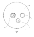
- the top view in FIG. 3 illustrates the opening 27, in which the closure plug 26 can be used for pressure-tight closure.
- appropriately trained conical contact surfaces are provided.
- the tissue cells accumulated in the collecting container 14 can then be removed via a corresponding suction lance or the like or can be supplied for further processing.
- connection element 25 with the attached suction member 20 is used pressure-tight.
- connection element 24 connected to the cover 15 can be seen, which serves for connection to the suction line 7 to the applicator 1.
- the bottom view under the lid 15 in FIG. 4 illustrates that the lid 15 has a circumferential annular step 32, which allows a pressure-tight insertion into the collecting container 14. Furthermore, it can be seen that an annular recess 33 is arranged around the opening 31. In this comes the communicating tube 16 to the plant and is fixed by the lid 15. At the same time, the connecting element 25 is guided through the opening 31 and held in this pressure-tight. Visible is a on the underside of the lid 15 downwardly projecting portion 34 which diametrically opposite the bolt 30 for receiving the collecting basket 28 has.
Landscapes
- Health & Medical Sciences (AREA)
- Life Sciences & Earth Sciences (AREA)
- Engineering & Computer Science (AREA)
- Heart & Thoracic Surgery (AREA)
- Biomedical Technology (AREA)
- General Health & Medical Sciences (AREA)
- Anesthesiology (AREA)
- Vascular Medicine (AREA)
- Veterinary Medicine (AREA)
- Public Health (AREA)
- Animal Behavior & Ethology (AREA)
- Hematology (AREA)
- Chemical & Material Sciences (AREA)
- Bioinformatics & Cheminformatics (AREA)
- Wood Science & Technology (AREA)
- Biotechnology (AREA)
- Zoology (AREA)
- Organic Chemistry (AREA)
- Microbiology (AREA)
- Genetics & Genomics (AREA)
- General Engineering & Computer Science (AREA)
- Sustainable Development (AREA)
- Biochemistry (AREA)
- Pathology (AREA)
- Molecular Biology (AREA)
- Cell Biology (AREA)
- Apparatus Associated With Microorganisms And Enzymes (AREA)
- Sampling And Sample Adjustment (AREA)
- External Artificial Organs (AREA)
Abstract
Description
- Die Erfindung betrifft eine Vorrichtung zum Trennen von Gewebezellen aus einer Flüssigkeit mit einem einen Sammelraum ausbildenden Sammelbehälter, der einerseits mit einer Unterdruckquelle verbunden ist und der andererseits mit einer Zuführleitung für ein Flüssigkeits-Gewebezellen-Gemisch verbunden ist.
- Vorrichtungen der gattungsgemäßen Art sind bekannt. So zeigt beispielsweise
WO 2009/149691 A2 ein Verfahren und eine Vorrichtung zum Trennen von Gewebezellen aus einer Flüssigkeit, wobei ein unter Vakuum stehender Gewebezellensammler eine Filtereinheit umfasst, die den Sammelbehälter in einem unteren Sammelraum für die Flüssigkeiten und einen mittleren Sammelraum für die Gewebezellen und einen oberen Vakuumraum aufteilt. Der untere Sammelraum für die Flüssigkeit und der obere Vakuumraum sind am Sammelraum für die Gewebezellen vorbei miteinander verbunden. - Der Erfindung liegt die Aufgabe zugrunde, eine Vorrichtung der gattungsgemäßen Art zu schaffen, die sich durch einen einfachen Aufbau auszeichnet und eine schonende Trennung der Gewebezellen aus einem Flüssigkeits-Gewebezellen-Gemisch gestattet.
- Erfindungsgemäß wird diese Aufgabe mittels einer Vorrichtung mit den in Anspruch 1 genannten Merkmalen gelöst. Dadurch, dass innerhalb des Sammelraumes eine kommunizierende Röhre angeordnet ist, die in einem Abstand zum Boden des Sammelbehälters mündet, wobei zwischen der kommunizierenden Röhre und dem Sammelraum oberhalb eines sich einstellenden Flüssigkeits-Gewebezellen-Gemischpegels eine Verbindung besteht und innerhalb der kommunizierenden Röhre ein mit der Unterdruckquelle verbundenes Saugelement angeordnet ist, ist vorteilhaft möglich, in besonders einfacher und schonender Weise eine Trennung der entnommenen Gewebezellen von der Flüssigkeit zu erreichen. Diese schonende Trennung ist insbesondere wichtig, damit die zuvor, beispielsweise einem menschlichen Körper, entnommenen Gewebezellen wieder aufgearbeitet und beispielsweise zum Wiedereinbringen in den menschlichen Körper geeignet sind. Mittels der in den Sammelraum eingreifenden, kommunizierenden Röhre, insbesondere durch das innerhalb der kommunizierenden Röhre angeordnete Saugelement, kann durch den dort anliegenden Unterdruck die Flüssigkeit abgesaugt werden, während sich die Gewebezellen im Sammelraum ablagern. Die Gewebezellen besitzen eine geringere Dichte als die Flüssigkeit, so dass diese durch Auftriebskräfte an die Oberfläche der Flüssigkeit drängen. Da die kommunizierende Röhre möglichst bodennah in den Sammelbehälter eingreift, stellt sich in der kommunizierenden Röhre ein auf gleichem Niveau befindlicher Flüssigkeitsspiegel wie in dem Sammelraum ein. Die Zellen verbleiben hierbei im Sammelraum, während die Flüssigkeit in der kommunizierenden Röhre aufsteigt. Von dort wird diese durch das dort eingreifende Saugelement abgesaugt. Durch die nachfolgende Zufuhr des Flüssigkeits-Gewebezellen-Gemisches ergibt sich über die kommunizierende Röhre dort ein gleicher Flüssigkeitsstand wie in dem Sammelraum. Mittels der Verbindung zwischen der kommunizierenden Röhre und dem Sammelraum oberhalb eines Flüssigkeits-Gewebezellen-Gemischpegels wird dafür Sorge getragen, dass sich in der kommunizierenden Röhre und dem Sammelraum ein Druckgleichgewicht einstellt, so dass hier der Effekt der kommunizierenden Röhre für das Absaugen der Flüssigkeit und das Verbleiben der Gewebezellen im Sammelraum ausgenutzt werden kann. Hierdurch wird die Zuführung des Flüssigkeits-Gewebezellen-Gemisches in den Sammelraum gewährleistet und andererseits die Trennung der Flüssigkeit von den Gewebezellen schonend ermöglicht.
- In bevorzugter Ausgestaltung der Erfindung ist vorgesehen, einen möglichst hohen und schlanken Sammelbehälter mit möglichst kleinem Durchmesser für das Auffangen eines Flüssigkeits-Gewebezellen-Gemisches zu verwenden. Hierdurch wird der Auftrieb der Gewebezellen im Flüssigkeitsgemisch konstruktiv begünstigt.
- Die im Sammelraum angeordnete kommunizierende Röhre hat oberhalb der Saugöffnung des eingeschlossenen Saugelementes eine Öffnung in den Sammelraum. Diese Öffnung ist verantwortlich für einen schnellen Druckausgleich zwischen der kommunizierenden Röhre mit dem eingeschlossenen Saugelement und dem Sammelraum. Je größer die Öffnung umso geringer ist der Sog, der in der kommunizierenden Röhre auf den Flüssigkeitspegel wirkt. Das beeinflusst den Niveauausgleich in positiver Weise und gibt dadurch dem Flüssigkeits-Gewebezellen-Gemisch im Sammelraum mehr Zeit zur Zelltrennung mittels Auftrieb.
- Die im Sammelraum angeordnete kommunizierende Röhre hat des Weiteren einen möglichst kleinen Abstand zum Behälterboden. Über diesen Spalt erfolgt der Niveauausgleich zwischen dem Flüssigkeits-Gewebezellen-Gemisch im Sammelraum und der aufsteigenden Flüssigkeit in der kommunizierenden Röhre. Die Gestaltung des Spaltes ist mitverantwortlich für die korrekte Trennung der Gewebezellen vom Rest des Flüssigkeitsgemisches. Ein kleiner Spalt hat eine Drosselfunktion, wodurch der Niveauausgleich positiv beeinflusst wird, was bedeutet, dass dem Flüssigkeits-Gewebezellen-Gemisch im Sammelraum mehr Zeit zur Zelltrennung mittels Auftrieb gegeben wird.
- Beim Beginn der Absaugung des Flüssigkeits-Gewebe-Zellengemisches, das heißt, im Behälter befindet sich noch kein derartiges Gemisch, stellen sich die gewünschten Druckverhältnisse innerhalb des Sammelbehälters schnell ein. Durch den konstruktiven Aufbau des Sammelbehälters bildet sich sofort ein weitestgehend gewebefreier Flüssigkeitsbereich, der über den Spalt zwischen dem Behälterboden und der kommunizierende Röhre zu einem Niveauausgleich zwischen dem Flüssigkeits-Gewebe-Zellengemisch im Sammelraum und dem Innenraum der kommunizierende Röhre führt. Mit fortdauernder Absaugung und steigendem Flüssigkeits-Gewebezellen-Gemisch-Pegel im Sammelraum und in der kommunizierenden Röhre taucht das von der kommunizierenden Röhre umschlossene Saugelement in die abzusaugende Flüssigkeit ein. Um dem Flüssigkeits-Gewebezellen-Gemisch zusätzlich Zeit zur Zelltrennung mittels Auftrieb zu gegeben, erfolgt erst jetzt durch die Öffnung des Saugelementes das Absaugen der Flüssigkeit, die über die Saugleitung in den Flüssigkeitsbehälter befördert wird.
- Zum Ende der Absaugung, bei gewünschter Gewebezellmenge im Sammelraum, lässt sich in Abhängigkeit von der eingestellten Eintauchtiefe des Saugelementes der gewebefreie Flüssigkeitsbereich über dem Behälterboden und in der kommunizierenden Röhre verringern, bis sich idealerweise nur noch Gewebezellen im Sammelbehälter befinden.
- In weiterer bevorzugter Ausgestaltung der Erfindung ist vorgesehen, dass die kommunizierende Röhre an ihrem dem Boden zugewandten Ende randoffene Ausnehmungen aufweist. Hier wird vorteilhaft möglich, die kommunizierende Röhre sich mit ihrem unteren Ende am Boden des Sammelgefäßes abstützen zu lassen, während die randoffenen Ausnehmungen die Verbindungen zum Übertritt der Flüssigkeit von dem Sammelraum in die kommunizierende Röhre gestattet. Neben einer Lagerung der Röhre im Deckel ist durch diese Abstützung am Boden eine besonders stabile, auf robuste Betriebsweisen angepasste, Vorrichtung geschaffen.
- Darüber hinaus ist in bevorzugter Ausgestaltung der Erfindung vorgesehen, dass eine Mündung des Saugelementes unterhalb der über dem Flüssigkeits-Gewebezellen-Gemischpegel angeordneten Verbindung zwischen der kommunizierenden Röhre und dem Sammelraum liegt. Hierdurch wird vorteilhaft erreicht, dass ein möglichst großes Volumen innerhalb des Sammelbehälters zum Sammeln der Gewebezellen bereitgestellt werden kann. Diese Verbindung zwischen dem Sammelraum und der kommunizierenden Röhre liegt somit oberhalb der Saugmündung des Saugelementes.
- Ferner ist in bevorzugter Ausgestaltung der Erfindung vorgesehen, dass das Saugelement eine variable Länge aufweist und/oder in variabler Länge einstellbar ist. Dadurch wird vorteilhaft möglich, die Vorrichtung auf unterschiedliche zu sammelnde Gewebezellenmengen abzustimmen. Je kürzer das Saugelement ist, umso später gelangt dieses in Kontakt mit dem Flüssigkeitspegel in der kommunizierenden Röhre. Das bedeutet, es tritt zunächst erst eine entsprechend größere Menge des Flüssigkeits-Gewebezellen-Gemisches in den Sammelraum ein, bevor das Absaugen der Flüssigkeit einsetzt. Die Gewebezellen haben hierdurch auch mehr Zeit, aufgrund der Auftriebswirkung sich an der Oberfläche der Flüssigkeit zu sammeln, so dass die Flüssigkeit dann anschließend von unten über die kommunizierende Röhre abgesaugt wird. Auch lassen sich hierdurch größere Gewebezellmengen auffangen als mit einem längeren Saugelement.
- Darüber hinaus ist in weiterer bevorzugter Ausgestaltung der Erfindung vorgesehen, dass der Sammelbehälter eine verschließbare Entnahmeöffnung für die gesammelten Gewebezellen umfasst. Hierdurch wird vorteilhaft möglich, die in dem Sammelraum gesammelten Gewebezellen problemlos und schonend zu entnehmen, beispielsweise abzusaugen. Hierdurch muss die gesamte Vorrichtung nicht von der Unterdruckquelle und der Einrichtung zum Zuführen des Flüssigkeits-Gewebezellen-Gemisches getrennt werden. Der Absaugvorgang des Flüssigkeits-Gewebezellen-Gemisches kann für die Entnahme der angesammelten Gewebezellen kurzfristig unterbrochen werden und kann anschließend ohne Neuinstallation fortgesetzt werden. Hierdurch ergibt sich eine besonders effektive Einsatzmöglichkeit für die erfindungsgemäße Vorrichtung.
- Schließlich ist in weiterer bevorzugter Ausgestaltung der Erfindung vorgesehen, dass der Sammelbehälter mittels eines Deckels verschließbar ist, der eine Öffnung für den Anschluss der Unterdruckquelle mittels des verstellbaren Saugelementes, eine Öffnung für einen Anschluss der Zuführleitung des Flüssigkeits-Gewebezellen-Gemisches und die verschließbare Entnahmeöffnung aufweist. Hierdurch wird vorteilhaft erreicht, dass alle funktionalen Anschlusselemente in dem Deckel integriert sind und der Sammelbehälter insgesamt sich durch einen einfachen, auch kostengünstig in großer Stückzahl herstellbaren Aufbau auszeichnet.
- Ferner ist in bevorzugter Ausgestaltung der Erfindung vorgesehen, dass der Deckel an seiner dem Sammelraum zugewandten Seite Befestigungsmittel für einen Auffangkorb umfasst, der unterhalb der Öffnung für den Anschluss der Zuführleitung für das Flüssigkeits-Gewebezellen-Gemisch angeordnet ist. Hierdurch wird vorteilhaft ermöglicht, dass der Auffangkorb für ein schonendes Überführen des Flüssigkeits-Gewebezellen-Gemisches in den Sammelraum sorgt. Dieses tritt somit nicht mit großer Geschwindigkeit auf die bereits gesammelten Gewebezellen, sondern wird durch den Auffangkorb zunächst im Sinne eines Strömungswiderstandes beruhigt und fließt dann kontrolliert in den Sammelraum ab. Unerwünschte Gewebeanteile, wie z. B. Bindegewebe, werden über den Auffangkorb herausgefiltert und gelangen somit nicht in den Sammelraum.
- Die Materialien der erfindungsgemäßen Vorrichtung, insbesondere der Sammelbehälter, der Deckel, die kommunizierende Röhre, das Saugelement und der Auffangkorb sowie die erforderlichen Anschluss- und Verbindungsstücke bestehen aus einem für klinische Einsatzzwecke geeigneten Material, beispielsweise Kunststoff und/oder Metall.
- Weitere bevorzugte Ausgestaltungen der Erfindung ergeben sich aus den übrigen, in den Unteransprüchen genannten Merkmalen.
- Die Erfindung wird nachfolgend in einem Ausführungsbeispiel anhand der zugehörigen Zeichnungen näher erläutert. Es zeigen:
- Figur 1
- eine schematische Darstellung einer Einrichtung zum Flüssigkeitsstrahltrennen mit integrierter erfindungsgemäßer Vorrichtung zum Trennen von Gewebezellen aus einer Flüssigkeit;
- Figur 2
- eine schematische Perspektivansicht der erfindungsgemäßen Vorrichtung zum Trennen von Gewebezellen, sowohl im Zusammenbau als auch in Explosionsdarstellung;
- Figur 3
- eine Draufsicht auf einen Deckel der Vorrichtung gemäß
Figur 2 und - Figur 4
- eine Druntersicht auf den Deckel gemäß der Vorrichtung gemäß
Figur 2 . -
Figur 1 zeigt eine Einrichtung zum Flüssigkeitsstrahltrennen mit einem von der Hand eines Operateurs bedienbaren Applikator 1 zum wasserstrahlunterstützten Trennen und Absaugen von Gewebezellen aus einer biologischen Struktur, mit einer Druckstrahleinrichtung 2, mit einem Druckerzeuger 3 und einer Druckleitung 4 zur Versorgung des Applikators 1 mit einem definierten Flüssigkeitsstrahl sowie einer Saugeinrichtung 5 zur Entsorgung der abgetrennten Gewebeteile (Gewebezellen) und der verwendeten Arbeitsflüssigkeit und der körpereigenen Flüssigkeit aus dem Körper 1. Die Saugeinrichtung 5 umfasst einen Vakuumerzeuger 6 und eine Saugleitung 7, wobei die Saugleitung 7 den Vakuumerzeuger 6 mit dem Applikator 1 durchgehend verbindet. Im Bereich des Applikators 1 besitzt die Saugleitung 7 einen verschließbaren Bypass 8, der die Saugleitung 7 mit der Atmosphäre verbindet. In der Saugleitung 7 befindet sich ein Restflüssigkeitssammler 9 für die abgesaugte Flüssigkeit mit einem verschließbaren Auffangbehälter 10 sowie einem Eingangsanschluss 11 und einem Ausgangsanschluss 12 für die Saugleitung 7. Der Restflüssigkeitssammler 9 für die ausgefilterte Flüssigkeit ist in Saugrichtung vor dem Vakuumerzeuger 6 angeordnet. Zwischen dem Restflüssigkeitssammler 9 und dem Applikator 1 ist ein Gewebezellensammler 13 in die Saugleitung 7 geschaltet. - Der Gewebezellensammler 13 besteht aus einem zylindrischen Sammelbehälter 14, der mit einem Deckel 15 druckdicht verschlossen ist. Der Sammelbehälter 14 ist vorzugsweise zylindrisch ausgebildet. Vorzugsweise ist der Sammelbehälter 14 zur Beobachtung des Füllstandes und zur Bewertung des Zustandes der aufgefangenen Gewebezellen transparent ausgeführt. Zur Beobachtung des Füllstandes besitzt der Sammelbehälter 14 eine Füllstandsanzeige.
- Im Sammelbehälter 14 ist eine kommunizierende Röhre 16 angeordnet. Die kommunizierende Röhre 16 mündet in einem Abstand über einem Boden 17 des Sammelbehälters 14. Hierdurch kommt es zur Ausbildung einer (unteren) Verbindung zwischen der kommunizierenden Röhre 16 und einem Sammelraum 18 innerhalb des Sammelbehälters 14. Die kommunizierende Röhre 16 ist an dem Deckel 15 befestigt und umgreift einen Anschluss 19 für die Saugleitung 7 in Richtung des Vakuumerzeugers 6 (Unterdruckquelle). Die kommunizierende Röhre 16 umgreift eine in
Figur 1 nicht gezeigte Öffnung für den Anschluss der Saugleitung 7. Diese Öffnung ist unmittelbar mit einem Saugelement 20 verbunden, das sich in die kommunizierende Röhre 16 hinein erstreckt. Die kommunizierende Röhre 16 besitzt wenigstens eine Öffnung 21, so dass es zu einer (oberen) Verbindung zwischen dem Innenraum der kommunizierenden Röhre 16 und dem Sammelraum 18 kommt. Diese wenigstens eine Öffnung 21 befindet sich oberhalb eines hier angedeuteten Pegels 22 eines Flüssigkeits-Gewebezellen-Gemisches 23 innerhalb des Sammelbehälters 14. Die Länge des Saugelementes 20 bestimmt die Höhe des Pegels 22. - Die in
Figur 1 dargestellte Einrichtung zum Flüssigkeitsstrahltrennen zeigt folgende Funktion: - Bei Anwendung des Flüssigkeitsstrahltrennverfahrens tritt aus dem Applikator 1 ein definierter Flüssigkeitstrennstrahl aus, dessen Wirkung durch den in der Druckstrahleinrichtung erzeugten Flüssigkeitsdruck und die konstruktive Ausführung des Applikators 1 bestimmt wird. Diese Wirkung ist darauf gerichtet, Gewebezellen aus einer biologischen Struktur in schonender Weise herauszutrennen. Die so abgetrennten Gewebezellen werden zusammen mit der eingespritzten Arbeitsflüssigkeit und den weiteren körpereigenen Flüssigkeiten durch ein in der Saugeinrichtung 5 erzeugtes Vakuum abgesaugt. Dieses Verfahren wird häufig bei der Fettabsaugung angewendet. Immer dann, wenn die derart abgesaugten Gewebezellen einer Wiederverwendung zugeführt werden sollen, werden diese Gewebezellen aus dem Flüssigkeits-Gewebezellen-Gemisch separiert. Dies geschieht durch den Gewebezellensammler 13.
- Bei einer Stand-By-Stellung hält der Operateur den verschließbaren Bypass 8 geöffnet, so dass keine Absaugung erfolgt, sondern nur atmosphärische Luft angesaugt und durch den Gewebezellensammler 13 transportiert wird. Hierbei passiert die Luft den Gewebezellensammler 13 über den oberen Bereich des Sammelraumes 18, die kommunizierende Röhre 16 mit der Öffnung 21 sowie das Saugelement 20 in Richtung des Vakuumerzeugers 6.
- In einer Betriebsstellung ist der verschließbare Bypass 8 durch den Operateur verschlossen, so dass sich die Saugkraft des Vakuumerzeugers 6 auf das Operationsfeld überträgt. Hierdurch werden die abgetrennten Gewebeteile (Gewebezellen) und die verschiedenen Flüssigkeiten aufgenommen und zum Gewebezellensammler 13 transportiert. Im Gewebezellensammler 13 gelangt dieses Gemisch aus Gewebezellen und Flüssigkeit über den Eingangsstutzen in den Sammelraum 18. Innerhalb des Sammelraums 18 steigt der Pegel des Flüssigkeits-Gewebezellen-Gemisches 23 an, wobei die Gewebezellen aufgrund ihrer geringeren Dichte eine Auftriebskraft erfahren und innerhalb des Flüssigkeits-Gewebezellen-Gemisches 23 an die Oberfläche aufsteigen, also in Richtung des Pegels 22 drängen. In der kommunizierenden Röhre 16 herrscht der gleiche Pegelstand wie im Sammelraum 18. Über die Verbindung zwischen dem unteren Ende der kommunizierenden Röhre in Nähe des Bodens 17 und dem Sammelraum 18 steigt in der kommunizierenden Röhre im Wesentlichen nur die Flüssigkeit des Flüssigkeits-Gewebezellen-Gemisches 23 auf. Die Gewebezellen verbleiben im Sammelraum 18 während die Flüssigkeit in der kommunizierenden Röhre 16 aufsteigt. Nachdem der Pegel 22 so weit angestiegen ist, dass die Mündung des Saugelementes 20 erreicht ist, wird die Flüssigkeit innerhalb der kommunizierenden Röhre 16 in Richtung des Auffangbehälters 10 abgesaugt. Dieser Vorgang wird so weit fortgesetzt, bis im Sammelraum 18 die gewünschte oder die maximal mögliche Menge an Gewebezellen gesammelt wurde. Es wird deutlich, dass die Länge des Saugelementes 20 die Höhe des Pegelstandes 22 beeinflusst. Je kürzer das Saugelement 20, umso höher kann der Pegel 22 innerhalb des Sammelbehälters 14 liegen und umso größer ist die ansammelbare Menge an Gewebezellen innerhalb des Sammelraums 18.
- Über die wenigstens eine Öffnung 21 zwischen der kommunizierenden Röhre 16 und dem Sammelraum 18 wird ein Druckausgleich zwischen dem Sammelraum 18 und der kommunizierenden Röhre erreicht, so dass Flüssigkeit in der kommunizierenden Röhre - aufgrund der Gesetzmäßigkeit der kommunizierenden Röhren - zu dem gleichen Pegel aufsteigt wie das Flüssigkeits-Gewebezellen-Gemisch 23 im Sammelraum 18.
- Der freie Querschnitt zwischen der kommunizierenden Röhre 16 im Bereich des Bodens 17 und dem Sammelraum 18 ist möglichst so gering bemessen, dass durch diesen nur die Flüssigkeit aber im Wesentlichen keine Gewebezellen in die kommunizierende Röhre 16 gelangen können. Nach einem nicht gezeigten Ausführungsbeispiel kann hierzu die kommunizierende Röhre 16 an ihrem unteren Ende randoffene Aufnehmungen aufweisen, so dass sich die Röhre 16 am Boden 17 abstützen kann und trotzdem ein freier Querschnitt zwischen der kommunizierenden Röhre 16 und dem Sammelraum 18 zum Übertritt der Flüssigkeit verbleibt.
-
Figur 2 zeigt eine schematische Perspektivansicht des Sammelbehälters 14, einmal in der Zusammenbausituation und in Einzeldarstellung einiger Teile. Gleiche Teile wie inFigur 1 sind mit gleichen Bezugszeichen versehen und nicht nochmals erläutert. - Es wird deutlich, dass der Sammelbehälter 14 durch den Deckel 15 druckdicht verschlossen ist. Der Deckel 15 besitzt ein Anschlusselement 25 zur Verbindung über die Saugleitung 7 mit dem Auffangbehälter 10. Ferner ist ein Anschlusselement 24 dargestellt zur Verbindung der Saugleitung 7 in Richtung des Applikators 1. Das Anschlusselement 25 ist mit dem Saugelement 20 verbunden. Ferner ist ein Verschlussstopfen 26 gezeigt, mittels dem eine Öffnung 27 (
Figur 3 ) im Deckel 15 verschließbar ist. Zu erkennen ist ferner die kommunizierende Röhre 16, innerhalb der das Saugelement 20 angeordnet ist. Die kommunizierende Röhre 16 besitzt die Öffnungen 21 zur (oberen) Verbindung mit dem Sammelraum 18. -
Figur 2 zeigt ferner einen Auffangkorb 28, der an der Unterseite des Deckels 15 befestigbar ist. Hierzu besitzt der Auffangkorb 28 Rastverbindungen 29 nach Art eines Bajonettverschlusses, die mit entsprechenden Zapfen 30 (Figur 4 ) an der Unterseite des Deckels korrespondieren. Der Auffangkorb 28 besitzt eine im Wesentlichen zylindrische Gestalt mit über dem Umfang angeordneten Durchbrüchen. Der Auffangkorb 28 ist direkt unterhalb des Anschlusses 24 angeordnet. Auf diese Weise gelangt das über den Applikator 1 abgesaugte Flüssigkeits-Gewebezellen-Gemisch 23 zunächst in den Auffangkorb 28 und gelangt von diesem dann in den eigentlichen Sammelraum 18. Der Auffangkorb 28 dient einer Beruhigung des Flüssigkeits-Gewebezellen-Gemisches 23, das über die Saugleitung 7 in dem Sammelbehälter 14 gelangt. Insofern werden die im Sammelraum 18 bereits gesammelten Gewebezellen nicht direkt mit der Strömung des einfließenden Flüssigkeits-Gewebezellen-Gemisches 23 belastet. - In den
Figuren 3 und4 ist der Deckel 15 jeweils in einer Draufsicht und einer Druntersicht gezeigt. Die Draufsicht inFigur 3 verdeutlicht die Öffnung 27, in die der Verschlussstopfen 26 zum druckdichten Verschluss einsetzbar ist. Hierzu sind entsprechend ausgebildete konische Anlageflächen vorgesehen. Bei Entfernen des Verschlussstopfens 26 besteht über die Öffnung 27 ein Zugang zu dem Sammelraum 18. Über eine entsprechende Sauglanze oder dergleichen können dann die im Sammelbehälter 14 angesammelten Gewebezellen entnommen werden beziehungsweise einer weiteren Verarbeitung zugeführt werden. - Ersichtlich ist ferner eine Öffnung 31, in die von der Oberseite des Deckels 15 das Anschlusselement 25 mit dem daran befestigten Saugelement 20 druckdicht eingesetzt wird. Darüber hinaus ist das mit dem Deckel 15 verbundene Anschlusselement 24 erkennbar, das der Verbindung mit der Saugleitung 7 zum Applikator 1 dient.
- Die Druntersicht unter den Deckel 15 in
Figur 4 verdeutlicht, dass der Deckel 15 eine umlaufende Ringstufe 32 aufweist, die ein druckdichtes Einsetzen in den Sammelbehälter 14 gestattet. Ferner ist erkennbar, dass um die Öffnung 31 eine ringförmige Vertiefung 33 angeordnet ist. In diese kommt die kommunizierende Röhre 16 zur Anlage und wird durch den Deckel 15 fixiert. Gleichzeitig wird das Anschlusselement 25 durch die Öffnung 31 geführt und in dieser druckdicht gehalten. Erkennbar ist ein an der Unterseite des Deckels 15 nach unten überspringender Bereich 34, der diametral gegenüberliegend die Bolzen 30 zur Aufnahme des Auffangkorbes 28 aufweist. -
- 1
- Applikator
- 2
- Druckstrahleinrichtung
- 3
- Druckerzeuger
- 4
- Druckleitung
- 5
- Saugeinrichtung
- 6
- Vakuumerzeuger
- 7
- Saugleitung
- 8
- Bypass
- 9
- Restflüssigkeitssammler
- 10
- Auffangbehälter
- 11
- Eingangsanschluss
- 12
- Ausgangsanschluss
- 13
- Gewebezellensammler
- 14
- Sammelbehälter
- 15
- Deckel
- 16
- kommunizierende Röhre
- 17
- Boden
- 18
- Sammelraum
- 19
- Anschluss
- 20
- Saugelement
- 21
- Öffnung
- 22
- Pegel
- 23
- Flüssigkeits-Gewebezellen-Gemisch
- 24
- Anschlusselement
- 25
- Anschlusselement
- 26
- Verschlussstopfen
- 27
- Öffnung
- 28
- Auffangkorb
- 29
- Rastverbindung
- 30
- Zapfen/Bolzen
- 31
- Öffnung
- 32
- Ringstufe
- 33
- ringförmige Vertiefung
- 34
- überspringender Bereich
Claims (7)
- Vorrichtung zum Trennen von Gewebezellen aus einer Flüssigkeit, mit einem einen Sammelraum ausbildenden Sammelbehälter, der einerseits mit einer Unterdruckquelle verbunden ist und der andererseits mit einer Zuführleitung für das Flüssigkeits-Gewebezellen-Gemisch verbunden ist,
dadurch gekennzeichnet, dass
innerhalb des Sammelraumes (18) eine kommunizierende Röhre (16) angeordnet ist, die in einem Abstand zum Boden (17) des Sammelbehälters (14) mündet, wobei zwischen der kommunizierenden Röhre (16) und dem Sammelraum (18) oberhalb eines sich im Sammelbehälter (14) einstellenden Flüssigkeits-Gewebezellen-Gemischpegels (22) eine Verbindung (21) besteht und innerhalb der kommunizierenden Röhre (16) ein mit der Unterdruckquelle (6) verbundenes Saugelement (20) angeordnet ist. - Vorrichtung nach Anspruch 1,
dadurch gekennzeichnet, dass
der Abstand der kommunizierenden Röhre (16) zum Boden (17) des Sammelbehälters (14) so gewählt ist, dass ein freier Querschnitt zwischen der kommunizierenden Röhre (16) und dem Sammelraum (18) am Boden (17) kleiner ist als ein freier Querschnitt der Verbindung (21) zwischen der kommunizierenden Röhre (16) und dem Sammelraum (18) oberhalb des Flüssigkeits-Gewebezellen-Gemischpegels (22). - Vorrichtung nach einem der vorhergehenden Ansprüche,
dadurch gekennzeichnet, dass
die kommunizierende Röhre (16) an ihrem dem Boden (17) zugewandten Ende randoffene Ausnehmungen aufweist. - Vorrichtung nach einem der vorhergehenden Ansprüche,
dadurch gekennzeichnet, dass
das Saugelement (20) eine variable Länge aufweist und/oder in variabler Länge einstellbar ist. - Vorrichtung nach einem der vorhergehenden Ansprüche,
dadurch gekennzeichnet, dass
der Sammelbehälter (14) eine verschließbare Entnahmeöffnung (27) für die gesammelten Gewebezellen umfasst. - Vorrichtung nach einem der vorhergehenden Ansprüche,
dadurch gekennzeichnet, dass
der Sammelbehälter (14) mittels eines Deckels (15) verschließbar ist, der eine Öffnung (31) für den Anschluss der Unterdruckquelle, ein Anschlusselement (24) zum Anschluss einer Zuführleitung für das Flüssigkeits-Gewebezellen-Gemisch (23) und die verschließbare Entnahmeöffnung (27) aufweist. - Vorrichtung nach einem der vorhergehenden Ansprüche,
dadurch gekennzeichnet, dass
der Deckel (15) an seiner dem Sammelraum (18) zugewandten Seite Befestigungsmittel (30) für einen Auffangkorb (28) umfasst.
Priority Applications (1)
| Application Number | Priority Date | Filing Date | Title |
|---|---|---|---|
| PL10191337T PL2353625T3 (pl) | 2010-01-27 | 2010-11-16 | Urządzenie do oddzielania komórek tkanki od cieczy |
Applications Claiming Priority (3)
| Application Number | Priority Date | Filing Date | Title |
|---|---|---|---|
| DE201010001292 DE102010001292B4 (de) | 2010-01-27 | 2010-01-27 | Vorrichtung zum Trennen von Gewebezellen aus einer Flüssigkeit |
| US30450310P | 2010-02-15 | 2010-02-15 | |
| US12/817,428 US8801682B2 (en) | 2010-01-27 | 2010-06-17 | Apparatus for separating tissue cells from a fluid |
Publications (2)
| Publication Number | Publication Date |
|---|---|
| EP2353625A1 true EP2353625A1 (de) | 2011-08-10 |
| EP2353625B1 EP2353625B1 (de) | 2014-07-02 |
Family
ID=43991330
Family Applications (1)
| Application Number | Title | Priority Date | Filing Date |
|---|---|---|---|
| EP10191337.4A Active EP2353625B1 (de) | 2010-01-27 | 2010-11-16 | Vorrichtung zum Trennen von Gewebezellen aus einer Flüssigkeit |
Country Status (4)
| Country | Link |
|---|---|
| US (1) | US8801682B2 (de) |
| EP (1) | EP2353625B1 (de) |
| ES (1) | ES2504266T3 (de) |
| PL (1) | PL2353625T3 (de) |
Families Citing this family (38)
| Publication number | Priority date | Publication date | Assignee | Title |
|---|---|---|---|---|
| ES2658609T3 (es) | 2008-09-02 | 2018-03-12 | Tautona Group Lp | Hilos de ácido hialurónico y/o derivados de los mismos, métodos para fabricar los mismos, y usos de los mismos |
| US20110172180A1 (en) | 2010-01-13 | 2011-07-14 | Allergan Industrie. Sas | Heat stable hyaluronic acid compositions for dermatological use |
| EP3078388B1 (de) | 2010-03-22 | 2019-02-20 | Allergan, Inc. | Vernetzte hydrogele zur weichgewebevergrösserung |
| US8900571B2 (en) | 2010-08-19 | 2014-12-02 | Allergan, Inc. | Compositions and soft tissue replacement methods |
| US8697057B2 (en) | 2010-08-19 | 2014-04-15 | Allergan, Inc. | Compositions and soft tissue replacement methods |
| US8926963B2 (en) | 2010-08-19 | 2015-01-06 | Allergan, Inc. | Compositions and soft tissue replacement methods |
| US8697056B2 (en) | 2010-08-19 | 2014-04-15 | Allergan, Inc. | Compositions and soft tissue replacement methods |
| US8883139B2 (en) | 2010-08-19 | 2014-11-11 | Allergan Inc. | Compositions and soft tissue replacement methods |
| US8894992B2 (en) | 2010-08-19 | 2014-11-25 | Allergan, Inc. | Compositions and soft tissue replacement methods |
| US8741281B2 (en) | 2010-08-19 | 2014-06-03 | Allergan, Inc. | Compositions and soft tissue replacement methods |
| US8889123B2 (en) | 2010-08-19 | 2014-11-18 | Allergan, Inc. | Compositions and soft tissue replacement methods |
| US9005605B2 (en) | 2010-08-19 | 2015-04-14 | Allergan, Inc. | Compositions and soft tissue replacement methods |
| US20130096081A1 (en) | 2011-06-03 | 2013-04-18 | Allergan, Inc. | Dermal filler compositions |
| KR102238406B1 (ko) | 2011-06-03 | 2021-04-08 | 알러간 인더스트리 에스에이에스 | 항산화제를 포함하는 피부 충전제 조성물 |
| US9408797B2 (en) | 2011-06-03 | 2016-08-09 | Allergan, Inc. | Dermal filler compositions for fine line treatment |
| US9393263B2 (en) | 2011-06-03 | 2016-07-19 | Allergan, Inc. | Dermal filler compositions including antioxidants |
| US9662422B2 (en) | 2011-09-06 | 2017-05-30 | Allergan, Inc. | Crosslinked hyaluronic acid-collagen gels for improving tissue graft viability and soft tissue augmentation |
| US20130244943A1 (en) | 2011-09-06 | 2013-09-19 | Allergan, Inc. | Hyaluronic acid-collagen matrices for dermal filling and volumizing applications |
| USD771832S1 (en) * | 2014-06-17 | 2016-11-15 | Medline Industries, Inc. | Lid and screen assembly of a sample collection container with screen |
| EP3200838B1 (de) | 2014-09-30 | 2019-09-18 | Allergan Industrie, SAS | Stabile hydrogelzusammensetzungen mit additiven |
| HUE047971T2 (hu) | 2015-02-13 | 2020-05-28 | Allergan Ind Sas | Az arcelemek - például az áll - formázására, megnagyobbítására vagy korrekciójára szolgáló implantátumok |
| KR101638736B1 (ko) * | 2015-03-25 | 2016-07-11 | 가톨릭대학교 산학협력단 | 조직 샘플 포집장치 및 이를 포함하는 내시경 |
| DE102015109148B3 (de) * | 2015-06-10 | 2016-05-04 | Human Med Ag | Vorrichtung zum Separieren von regenerativen und adulten Stammzellen |
| ITUB20154668A1 (it) * | 2015-10-14 | 2017-04-14 | Mario Goisis | Dispositivo per la filtrazione del grasso estratto con procedure chirurgiche di liposuzione |
| US9671318B1 (en) | 2015-12-02 | 2017-06-06 | Medline Industries, Inc. | Specimen collector |
| USD788879S1 (en) * | 2015-12-31 | 2017-06-06 | HongKong EcoAqua Co., Ltd. | Water filter |
| EP3426400B1 (de) * | 2016-03-10 | 2020-09-02 | Arthrex Inc | System zur herstellung von proteinverstärkten seren |
| IL261057B (en) | 2016-03-10 | 2022-08-01 | Arthrex Inc | System and methods for preparing a thrombin serum |
| USD788880S1 (en) * | 2016-04-08 | 2017-06-06 | Hong Kong EcoAqua Co., Ltd. | Filter unit |
| CN110402154B (zh) | 2017-03-17 | 2022-09-20 | 史赛克公司 | 用于医用废弃物收集系统的歧管 |
| US12350418B2 (en) | 2019-04-12 | 2025-07-08 | Stryker Corporation | Manifold for a medical waste collection system |
| US11318242B2 (en) | 2019-04-12 | 2022-05-03 | Stryker Corporation | Manifold for a medical waste collection system |
| US10471188B1 (en) | 2019-04-12 | 2019-11-12 | Stryker Corporation | Manifold for filtering medical waste being drawn under vacuum into a medical waste collection system |
| USD930850S1 (en) | 2019-11-20 | 2021-09-14 | Stryker Corporation | Specimen collection tray |
| USD996640S1 (en) | 2019-11-11 | 2023-08-22 | Stryker Corporation | Specimen collection tray |
| USD956967S1 (en) | 2019-11-11 | 2022-07-05 | Stryker Corporation | Manifold housing for a medical waste collection device |
| USD919799S1 (en) | 2019-11-11 | 2021-05-18 | Stryker Corporation | Manifold housing for a medical waste collection device |
| USD1031076S1 (en) | 2019-11-20 | 2024-06-11 | Stryker Corporation | Specimen collection tray |
Citations (5)
| Publication number | Priority date | Publication date | Assignee | Title |
|---|---|---|---|---|
| US3685517A (en) * | 1970-09-18 | 1972-08-22 | Voys Inc Le | Aseptic disposable drainage receiver |
| EP0384585A1 (de) * | 1989-02-02 | 1990-08-29 | Stryker Corporation | System zur Blutkonservierung |
| EP1837045A1 (de) * | 2006-03-24 | 2007-09-26 | ATMOS MEDIZINTECHNIK GmbH & Co. | Absauggerät |
| EP2119461A2 (de) * | 2008-05-13 | 2009-11-18 | Eurosets S.r.l. | Vorrichtung zur postoperativen Autotransfusion mit verbesserter Effizienz |
| WO2009149691A2 (de) | 2008-06-10 | 2009-12-17 | Human Med Ag | Verfahren und vorrichtung zum trennen von gewebezellen aus einer flüssigkeit |
Family Cites Families (5)
| Publication number | Priority date | Publication date | Assignee | Title |
|---|---|---|---|---|
| US2936757A (en) | 1957-04-19 | 1960-05-17 | Herbert D Trace | Surgical drainage apparatus |
| JPH0734749B2 (ja) | 1988-02-03 | 1995-04-19 | 日本碍子株式会社 | エリスリトールの製造方法 |
| US5624418A (en) * | 1995-10-04 | 1997-04-29 | Shepard; R. David | Collection and separation device |
| US7776584B2 (en) * | 2003-08-01 | 2010-08-17 | Genetix Limited | Animal cell colony picking apparatus and method |
| US8100874B1 (en) * | 2009-05-22 | 2012-01-24 | Donnell Mark Jordan | Tissue refining device |
-
2010
- 2010-06-17 US US12/817,428 patent/US8801682B2/en active Active
- 2010-11-16 ES ES10191337.4T patent/ES2504266T3/es active Active
- 2010-11-16 EP EP10191337.4A patent/EP2353625B1/de active Active
- 2010-11-16 PL PL10191337T patent/PL2353625T3/pl unknown
Patent Citations (5)
| Publication number | Priority date | Publication date | Assignee | Title |
|---|---|---|---|---|
| US3685517A (en) * | 1970-09-18 | 1972-08-22 | Voys Inc Le | Aseptic disposable drainage receiver |
| EP0384585A1 (de) * | 1989-02-02 | 1990-08-29 | Stryker Corporation | System zur Blutkonservierung |
| EP1837045A1 (de) * | 2006-03-24 | 2007-09-26 | ATMOS MEDIZINTECHNIK GmbH & Co. | Absauggerät |
| EP2119461A2 (de) * | 2008-05-13 | 2009-11-18 | Eurosets S.r.l. | Vorrichtung zur postoperativen Autotransfusion mit verbesserter Effizienz |
| WO2009149691A2 (de) | 2008-06-10 | 2009-12-17 | Human Med Ag | Verfahren und vorrichtung zum trennen von gewebezellen aus einer flüssigkeit |
Also Published As
| Publication number | Publication date |
|---|---|
| ES2504266T3 (es) | 2014-10-08 |
| PL2353625T3 (pl) | 2015-03-31 |
| US8801682B2 (en) | 2014-08-12 |
| EP2353625B1 (de) | 2014-07-02 |
| US20110183406A1 (en) | 2011-07-28 |
Similar Documents
| Publication | Publication Date | Title |
|---|---|---|
| EP2353625B1 (de) | Vorrichtung zum Trennen von Gewebezellen aus einer Flüssigkeit | |
| DE102008027486B4 (de) | Verfahren und Vorrichtung zum Trennen von Gewebezellen aus einer Flüssigkeit | |
| DE2439392C2 (de) | Flüssigkeitsabsaug- und Sammelvorrichtung | |
| DE69529278T2 (de) | Filtrationsvorrichtung zur entfernung von leukozyten | |
| DE19620591B4 (de) | Vorrichtung zum Entfernen von Gasen aus Flüssigkeiten | |
| DE3122509C2 (de) | ||
| DE69013883T2 (de) | Pumpenanordnung. | |
| DE60317688T2 (de) | FLüSSIGKEITS-PROBENEHMER UND VERFAHREN | |
| DE10323068A1 (de) | Flüssigkeitstank | |
| DE102007027732A1 (de) | Abschäumer-Vorrichtung | |
| DE19650407A1 (de) | Blut-Gas-Trennverfahren und -Trennvorrichtung | |
| EP0846469B1 (de) | Blutabsaugvorrichtung | |
| DE60305763T2 (de) | Venöse Blutkammer in einem extrakorporalen Kreislauf | |
| DE102008030531A1 (de) | Verfahren und Vorrichtung zur Entfernung von Gas, insbesondere Luft aus Flotationsschaum und ihre Verwendung | |
| EP0098966A2 (de) | Vorrichtung zur Entnahme von Milchproben | |
| EP3682970A1 (de) | Vorrichtung zum abtrennen eines überstands einer flüssigen probe | |
| DE102010001292B4 (de) | Vorrichtung zum Trennen von Gewebezellen aus einer Flüssigkeit | |
| DE102005011740B4 (de) | Venöse Blasenfalle | |
| WO1991004087A1 (de) | Einrichtung zum absaugen von flüssigkeiten | |
| EP0345527B1 (de) | Ansaughilfe zur Flüssigkeitsentnahme aus einem Gefäss | |
| DE2415618B2 (de) | Filtervorrichtung zum trennen von blutfraktionen | |
| DE2932779A1 (de) | Vorrichtung zum stoppen eines fluessigkeitsflusses | |
| DE202009000639U1 (de) | Semipermeables Membranventil zur Entlüftungsregulierung | |
| EP0163749B1 (de) | Verfahren und Vorrichtung zum Trennen von Biomasse und anorganischen Bestandteilen aus dem Schlamm eines Methan-Reaktors einer anaeroben Abwasseranlage | |
| EP4001655B1 (de) | Tauchdruckpumpe für flüssigkeit und deren verwendung |
Legal Events
| Date | Code | Title | Description |
|---|---|---|---|
| PUAI | Public reference made under article 153(3) epc to a published international application that has entered the european phase |
Free format text: ORIGINAL CODE: 0009012 |
|
| AK | Designated contracting states |
Kind code of ref document: A1 Designated state(s): AL AT BE BG CH CY CZ DE DK EE ES FI FR GB GR HR HU IE IS IT LI LT LU LV MC MK MT NL NO PL PT RO RS SE SI SK SM TR |
|
| AX | Request for extension of the european patent |
Extension state: BA ME |
|
| 17P | Request for examination filed |
Effective date: 20120130 |
|
| 17Q | First examination report despatched |
Effective date: 20130416 |
|
| GRAJ | Information related to disapproval of communication of intention to grant by the applicant or resumption of examination proceedings by the epo deleted |
Free format text: ORIGINAL CODE: EPIDOSDIGR1 |
|
| GRAP | Despatch of communication of intention to grant a patent |
Free format text: ORIGINAL CODE: EPIDOSNIGR1 |
|
| INTG | Intention to grant announced |
Effective date: 20140314 |
|
| GRAS | Grant fee paid |
Free format text: ORIGINAL CODE: EPIDOSNIGR3 |
|
| GRAA | (expected) grant |
Free format text: ORIGINAL CODE: 0009210 |
|
| AK | Designated contracting states |
Kind code of ref document: B1 Designated state(s): AL AT BE BG CH CY CZ DE DK EE ES FI FR GB GR HR HU IE IS IT LI LT LU LV MC MK MT NL NO PL PT RO RS SE SI SK SM TR |
|
| REG | Reference to a national code |
Ref country code: GB Ref legal event code: FG4D Free format text: NOT ENGLISH |
|
| REG | Reference to a national code |
Ref country code: CH Ref legal event code: EP Ref country code: AT Ref legal event code: REF Ref document number: 675556 Country of ref document: AT Kind code of ref document: T Effective date: 20140715 |
|
| REG | Reference to a national code |
Ref country code: IE Ref legal event code: FG4D Free format text: LANGUAGE OF EP DOCUMENT: GERMAN |
|
| REG | Reference to a national code |
Ref country code: DE Ref legal event code: R096 Ref document number: 502010007364 Country of ref document: DE Effective date: 20140814 |
|
| REG | Reference to a national code |
Ref country code: ES Ref legal event code: FG2A Ref document number: 2504266 Country of ref document: ES Kind code of ref document: T3 Effective date: 20141008 |
|
| REG | Reference to a national code |
Ref country code: NL Ref legal event code: T3 |
|
| REG | Reference to a national code |
Ref country code: LT Ref legal event code: MG4D |
|
| PG25 | Lapsed in a contracting state [announced via postgrant information from national office to epo] |
Ref country code: FI Free format text: LAPSE BECAUSE OF FAILURE TO SUBMIT A TRANSLATION OF THE DESCRIPTION OR TO PAY THE FEE WITHIN THE PRESCRIBED TIME-LIMIT Effective date: 20140702 Ref country code: SE Free format text: LAPSE BECAUSE OF FAILURE TO SUBMIT A TRANSLATION OF THE DESCRIPTION OR TO PAY THE FEE WITHIN THE PRESCRIBED TIME-LIMIT Effective date: 20140702 Ref country code: CZ Free format text: LAPSE BECAUSE OF FAILURE TO SUBMIT A TRANSLATION OF THE DESCRIPTION OR TO PAY THE FEE WITHIN THE PRESCRIBED TIME-LIMIT Effective date: 20140702 Ref country code: NO Free format text: LAPSE BECAUSE OF FAILURE TO SUBMIT A TRANSLATION OF THE DESCRIPTION OR TO PAY THE FEE WITHIN THE PRESCRIBED TIME-LIMIT Effective date: 20141002 Ref country code: LT Free format text: LAPSE BECAUSE OF FAILURE TO SUBMIT A TRANSLATION OF THE DESCRIPTION OR TO PAY THE FEE WITHIN THE PRESCRIBED TIME-LIMIT Effective date: 20140702 Ref country code: BG Free format text: LAPSE BECAUSE OF FAILURE TO SUBMIT A TRANSLATION OF THE DESCRIPTION OR TO PAY THE FEE WITHIN THE PRESCRIBED TIME-LIMIT Effective date: 20141002 Ref country code: GR Free format text: LAPSE BECAUSE OF FAILURE TO SUBMIT A TRANSLATION OF THE DESCRIPTION OR TO PAY THE FEE WITHIN THE PRESCRIBED TIME-LIMIT Effective date: 20141003 Ref country code: PT Free format text: LAPSE BECAUSE OF FAILURE TO SUBMIT A TRANSLATION OF THE DESCRIPTION OR TO PAY THE FEE WITHIN THE PRESCRIBED TIME-LIMIT Effective date: 20141103 |
|
| PG25 | Lapsed in a contracting state [announced via postgrant information from national office to epo] |
Ref country code: CY Free format text: LAPSE BECAUSE OF FAILURE TO SUBMIT A TRANSLATION OF THE DESCRIPTION OR TO PAY THE FEE WITHIN THE PRESCRIBED TIME-LIMIT Effective date: 20140702 Ref country code: HR Free format text: LAPSE BECAUSE OF FAILURE TO SUBMIT A TRANSLATION OF THE DESCRIPTION OR TO PAY THE FEE WITHIN THE PRESCRIBED TIME-LIMIT Effective date: 20140702 Ref country code: IS Free format text: LAPSE BECAUSE OF FAILURE TO SUBMIT A TRANSLATION OF THE DESCRIPTION OR TO PAY THE FEE WITHIN THE PRESCRIBED TIME-LIMIT Effective date: 20141102 Ref country code: RS Free format text: LAPSE BECAUSE OF FAILURE TO SUBMIT A TRANSLATION OF THE DESCRIPTION OR TO PAY THE FEE WITHIN THE PRESCRIBED TIME-LIMIT Effective date: 20140702 Ref country code: LV Free format text: LAPSE BECAUSE OF FAILURE TO SUBMIT A TRANSLATION OF THE DESCRIPTION OR TO PAY THE FEE WITHIN THE PRESCRIBED TIME-LIMIT Effective date: 20140702 |
|
| REG | Reference to a national code |
Ref country code: PL Ref legal event code: T3 |
|
| REG | Reference to a national code |
Ref country code: DE Ref legal event code: R097 Ref document number: 502010007364 Country of ref document: DE |
|
| PG25 | Lapsed in a contracting state [announced via postgrant information from national office to epo] |
Ref country code: EE Free format text: LAPSE BECAUSE OF FAILURE TO SUBMIT A TRANSLATION OF THE DESCRIPTION OR TO PAY THE FEE WITHIN THE PRESCRIBED TIME-LIMIT Effective date: 20140702 Ref country code: DK Free format text: LAPSE BECAUSE OF FAILURE TO SUBMIT A TRANSLATION OF THE DESCRIPTION OR TO PAY THE FEE WITHIN THE PRESCRIBED TIME-LIMIT Effective date: 20140702 Ref country code: SK Free format text: LAPSE BECAUSE OF FAILURE TO SUBMIT A TRANSLATION OF THE DESCRIPTION OR TO PAY THE FEE WITHIN THE PRESCRIBED TIME-LIMIT Effective date: 20140702 Ref country code: RO Free format text: LAPSE BECAUSE OF FAILURE TO SUBMIT A TRANSLATION OF THE DESCRIPTION OR TO PAY THE FEE WITHIN THE PRESCRIBED TIME-LIMIT Effective date: 20140702 |
|
| PLBE | No opposition filed within time limit |
Free format text: ORIGINAL CODE: 0009261 |
|
| STAA | Information on the status of an ep patent application or granted ep patent |
Free format text: STATUS: NO OPPOSITION FILED WITHIN TIME LIMIT |
|
| 26N | No opposition filed |
Effective date: 20150407 |
|
| PG25 | Lapsed in a contracting state [announced via postgrant information from national office to epo] |
Ref country code: LU Free format text: LAPSE BECAUSE OF FAILURE TO SUBMIT A TRANSLATION OF THE DESCRIPTION OR TO PAY THE FEE WITHIN THE PRESCRIBED TIME-LIMIT Effective date: 20141116 Ref country code: MC Free format text: LAPSE BECAUSE OF FAILURE TO SUBMIT A TRANSLATION OF THE DESCRIPTION OR TO PAY THE FEE WITHIN THE PRESCRIBED TIME-LIMIT Effective date: 20140702 Ref country code: BE Free format text: LAPSE BECAUSE OF NON-PAYMENT OF DUE FEES Effective date: 20141130 |
|
| REG | Reference to a national code |
Ref country code: CH Ref legal event code: PL |
|
| PG25 | Lapsed in a contracting state [announced via postgrant information from national office to epo] |
Ref country code: CH Free format text: LAPSE BECAUSE OF NON-PAYMENT OF DUE FEES Effective date: 20141130 Ref country code: LI Free format text: LAPSE BECAUSE OF NON-PAYMENT OF DUE FEES Effective date: 20141130 |
|
| REG | Reference to a national code |
Ref country code: IE Ref legal event code: MM4A |
|
| PG25 | Lapsed in a contracting state [announced via postgrant information from national office to epo] |
Ref country code: IE Free format text: LAPSE BECAUSE OF NON-PAYMENT OF DUE FEES Effective date: 20141116 |
|
| REG | Reference to a national code |
Ref country code: FR Ref legal event code: PLFP Year of fee payment: 6 |
|
| PG25 | Lapsed in a contracting state [announced via postgrant information from national office to epo] |
Ref country code: SI Free format text: LAPSE BECAUSE OF FAILURE TO SUBMIT A TRANSLATION OF THE DESCRIPTION OR TO PAY THE FEE WITHIN THE PRESCRIBED TIME-LIMIT Effective date: 20140702 |
|
| PG25 | Lapsed in a contracting state [announced via postgrant information from national office to epo] |
Ref country code: SM Free format text: LAPSE BECAUSE OF FAILURE TO SUBMIT A TRANSLATION OF THE DESCRIPTION OR TO PAY THE FEE WITHIN THE PRESCRIBED TIME-LIMIT Effective date: 20140702 |
|
| PG25 | Lapsed in a contracting state [announced via postgrant information from national office to epo] |
Ref country code: MT Free format text: LAPSE BECAUSE OF FAILURE TO SUBMIT A TRANSLATION OF THE DESCRIPTION OR TO PAY THE FEE WITHIN THE PRESCRIBED TIME-LIMIT Effective date: 20140702 Ref country code: HU Free format text: LAPSE BECAUSE OF FAILURE TO SUBMIT A TRANSLATION OF THE DESCRIPTION OR TO PAY THE FEE WITHIN THE PRESCRIBED TIME-LIMIT; INVALID AB INITIO Effective date: 20101116 |
|
| REG | Reference to a national code |
Ref country code: FR Ref legal event code: PLFP Year of fee payment: 7 |
|
| REG | Reference to a national code |
Ref country code: FR Ref legal event code: PLFP Year of fee payment: 8 |
|
| PG25 | Lapsed in a contracting state [announced via postgrant information from national office to epo] |
Ref country code: MK Free format text: LAPSE BECAUSE OF FAILURE TO SUBMIT A TRANSLATION OF THE DESCRIPTION OR TO PAY THE FEE WITHIN THE PRESCRIBED TIME-LIMIT Effective date: 20140702 |
|
| PG25 | Lapsed in a contracting state [announced via postgrant information from national office to epo] |
Ref country code: AL Free format text: LAPSE BECAUSE OF FAILURE TO SUBMIT A TRANSLATION OF THE DESCRIPTION OR TO PAY THE FEE WITHIN THE PRESCRIBED TIME-LIMIT Effective date: 20140702 |
|
| PGFP | Annual fee paid to national office [announced via postgrant information from national office to epo] |
Ref country code: AT Payment date: 20221117 Year of fee payment: 13 |
|
| P01 | Opt-out of the competence of the unified patent court (upc) registered |
Effective date: 20230510 |
|
| PGFP | Annual fee paid to national office [announced via postgrant information from national office to epo] |
Ref country code: NL Payment date: 20231122 Year of fee payment: 14 |
|
| PGFP | Annual fee paid to national office [announced via postgrant information from national office to epo] |
Ref country code: TR Payment date: 20231107 Year of fee payment: 14 |
|
| PGFP | Annual fee paid to national office [announced via postgrant information from national office to epo] |
Ref country code: PL Payment date: 20231113 Year of fee payment: 14 |
|
| REG | Reference to a national code |
Ref country code: AT Ref legal event code: MM01 Ref document number: 675556 Country of ref document: AT Kind code of ref document: T Effective date: 20231116 |
|
| PG25 | Lapsed in a contracting state [announced via postgrant information from national office to epo] |
Ref country code: AT Free format text: LAPSE BECAUSE OF NON-PAYMENT OF DUE FEES Effective date: 20231116 |
|
| PG25 | Lapsed in a contracting state [announced via postgrant information from national office to epo] |
Ref country code: AT Free format text: LAPSE BECAUSE OF NON-PAYMENT OF DUE FEES Effective date: 20231116 |
|
| REG | Reference to a national code |
Ref country code: NL Ref legal event code: MM Effective date: 20241201 |
|
| PG25 | Lapsed in a contracting state [announced via postgrant information from national office to epo] |
Ref country code: NL Free format text: LAPSE BECAUSE OF NON-PAYMENT OF DUE FEES Effective date: 20241201 |
|
| PGFP | Annual fee paid to national office [announced via postgrant information from national office to epo] |
Ref country code: DE Payment date: 20251118 Year of fee payment: 16 |
|
| PGFP | Annual fee paid to national office [announced via postgrant information from national office to epo] |
Ref country code: GB Payment date: 20251120 Year of fee payment: 16 |
|
| PGFP | Annual fee paid to national office [announced via postgrant information from national office to epo] |
Ref country code: IT Payment date: 20251128 Year of fee payment: 16 |
|
| PGFP | Annual fee paid to national office [announced via postgrant information from national office to epo] |
Ref country code: FR Payment date: 20251120 Year of fee payment: 16 |
|
| PGFP | Annual fee paid to national office [announced via postgrant information from national office to epo] |
Ref country code: ES Payment date: 20251216 Year of fee payment: 16 |