EP2354285A1 - Dispositif de manipulation de fil à tricoter pour machine à tricoter à plat - Google Patents
Dispositif de manipulation de fil à tricoter pour machine à tricoter à plat Download PDFInfo
- Publication number
- EP2354285A1 EP2354285A1 EP11001055A EP11001055A EP2354285A1 EP 2354285 A1 EP2354285 A1 EP 2354285A1 EP 11001055 A EP11001055 A EP 11001055A EP 11001055 A EP11001055 A EP 11001055A EP 2354285 A1 EP2354285 A1 EP 2354285A1
- Authority
- EP
- European Patent Office
- Prior art keywords
- hook
- knitting yarn
- needle bed
- knitting
- guide groove
- Prior art date
- Legal status (The legal status is an assumption and is not a legal conclusion. Google has not performed a legal analysis and makes no representation as to the accuracy of the status listed.)
- Granted
Links
Images


Classifications
-
- D—TEXTILES; PAPER
- D04—BRAIDING; LACE-MAKING; KNITTING; TRIMMINGS; NON-WOVEN FABRICS
- D04B—KNITTING
- D04B15/00—Details of, or auxiliary devices incorporated in, weft knitting machines, restricted to machines of this kind
- D04B15/38—Devices for supplying, feeding, or guiding threads to needles
- D04B15/54—Thread guides
- D04B15/56—Thread guides for flat-bed knitting machines
- D04B15/565—Associated thread-clamping or thread-severing devices
-
- D—TEXTILES; PAPER
- D04—BRAIDING; LACE-MAKING; KNITTING; TRIMMINGS; NON-WOVEN FABRICS
- D04B—KNITTING
- D04B15/00—Details of, or auxiliary devices incorporated in, weft knitting machines, restricted to machines of this kind
- D04B15/66—Devices for determining or controlling patterns ; Program-control arrangements
- D04B15/82—Devices for determining or controlling patterns ; Program-control arrangements characterised by the needle cams used
Definitions
- the present invention relates to a knitting yarn holding device for a flatbed knitting machine, which is included in a knitting yarn holding and cutting device or the like, attached to an edge of a needle bed and driven in the same manner as a knitting needle to hold the knitting yarn.
- a knitting yarn holding and cutting device has been attached to an edge of a needle bed (for example, see Patent Literature 1).
- the knitting yarn holding and cutting device is mounted to a carriage that runs to shuttle between both edges of the needle bed, and has hook bars and a cutter bar selectively driven as in the case of a knitting needle by the use of a cam for knitting which selectively drives knitting needles.
- a flatbed knitting machine which has needle beds facing each other in the front and rear with a needle bed gap in-between, one cutter bar and a plurality of hook bars are installed to each needle bed on at least one edge side.
- the cutter bar and the hook bars are housed, in guide grooves formed between plates erectly set up on the needle bed so that the cutter bar and the hook bars become parallel to needle grooves for housing knitting needles in a state being able to slide therein.
- a blade for cutting a knitting yarn is installed, captures the knitting yarn when the cutter bar moves forward to the needle bed gap, and is pulled in the needle bed side to be withdrawn from the needle bed gap and to cut the knitting yarn.
- the hook bar has a hook installed to the vicinity of the head end on the needle bed gap side. When the hook bar is moved forward to the needle bed gap, the knitting yarn is fed to the rear side of the hook.
- the hook bar When the hook bar is withdrawn from the needle bed gap to pull in the hook bar into the guide groove of the needle bed, the hook bar supports and accepts the knitting yarn, captured on the rear side of the hook, by head end sides of plates on both sides of the guide groove, and holds the knitting yarn by clipping it between the inner surface of the plate and the outer surface of the hook.
- each hook bar corresponds to each yarn carrier used for knitting respectively, and holds the knitting yarn end part.
- a knitting yarn to be fed from one yarn carrier does not always consist of one string.
- a primary yarn containing a plurality of strings and a plating yarn that uses a string finer than that of the primary yarn are sometimes fed simultaneously to a knitting needle.
- plural strings are simultaneously fed from the same yarn feeder port of a yarn carrier as one knitting yarn.
- a yarn of particularly slippery material is fed as a knitting yarn.
- the present invention is a knitting yarn holding device for a flatbed knitting machine, being equipped with hook bars, each hook bar being housed in a guide groove, the guide groove being formed between plates at a end part in width direction of a needle bed and being parallel to needle grooves of the flatbed knitting machine, having a hook for holding a knitting yarn at a head end side, and being driven, by a cam mounted to a carriage which runs forth and back along the needle bed, so that the hook moving ahead and back relative to a needle bed gap, and for holding a knitting yarn by clipping the knitting yarn between side surfaces of a supporting accept parts installed at the head end on the needle bed gap side on both sides of a guide groove, and a latching stop part on a rear side of the hook, when the hook bar, which captures the knitting yarn on the rear side of the hook by moving the hook ahead and back relative to the needle bed gap, is withdrawn from the needle bed gap and is pulled in the guide groove, which comprising:
- said pressing member is energized to press the surface side of said hook bar inside said guide groove, and a groove for guiding the depressing part of the pressing member is provided on the surface side of said hook bar, and on the bottom part of the groove, a cam face for guiding the depressing part to approach said latching stop part in conjunction with the pull-in action of the hook bar into the guide groove is provided.
- said pressing member is a spacer which covers said hook bar on the surface side of the edge in the needle bed gap side of said guide groove, and said depressing part is installed at the head end of an elastic leg extended from the spacer in a state being energized to the bottom side direction of the guide groove.
- a notch is provided on the head end side of said plate in such a manner as to be formed to depart from the needle bed gap, and to the notch portion of the plate, there respectively provided are pressing plates, mounted to both sides of the spacer, having said supporting accept part at the head end part extending to the needle bed gap side, and energizing inwards in such a manner as to press said hook bar from both sides of said guide groove by the head end part.
- a depressing part of a pressing member gathers and presses the knitting yarn at the latching stop part of the hook from a direction intersecting with the direction of pulling in the hook bar into the guide groove.
- the knitting yarn is securely gathered at the latching stop part of the hook, and the knitting yarn is pressed from a direction different from the pressing direction between the latching stop part of the hook and the supporting accept part of the head end on both sides of the guide groove. Accordingly, the knitting yarn is able to be held securely and with care to prevent it from dropping out.
- the depressing part of the pressing member is guided by the cam face on the bottom of the groove provided on the surface side of the hook bar in the guide groove, so that the knitting yarn is able to be gathered and pressed at the latching stop part in conjunction with the motion to pull in the hook bar into the guide groove.
- a spacer that covers the hook bar at the edge on the needle bed gap side of the guide groove is provided with a function as a pressing member, and the knitting yarn is therefore able to be gathered and pressed at the latching stop part on the rear side of the hook by the depressing part which is extended from the spacer.
- the knitting yarn is held between side surfaces, of the supporting accept part of the head end portion extended from a pressing plate to the needle bed gap side, and of the latching stop part of the hook of the hook bar, and the pressing plate is mounted on both sides of the spacer and energizing inwards, so that the knitting yarn is able to be clipped and securely held with intervals narrower than those where the knitting yarn is clipped between the plate inner surface and the hook outer surface. Even if a groove that guides the depressing part of the pressing member is formed on the surface side of the hook bar, the knitting yarn is able to be pressed by the head end part of the pressing plate from both sides in such a manner that the portions on both sides of the groove of the hook do not open.
- a structure of a knitting yarn holding device 1 as one embodiment of the present invention will be explained hereinafter.
- the needle bed is shown in a horizontal state but in actual flatbed knitting machines, the needle bed is tilted in such a manner that the needle bed gap 2 side is higher and the side departing from the needle bed gap 2 lowers.
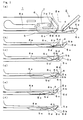
- Fig. 1 simply shows a general structure and a movement of a knitting yarn holding device 1 as one embodiment of the present invention.
- the knitting yarn holding device 1 is installed on a needle bed gap 2 side of a needle bed whose illustration is omitted in a flatbed knitting machine.
- a yarn feeder port 3 feeds a knitting yarn to knitting needles while moving in the direction perpendicular to the paper surface.
- the knitting yarn holding device 1 allows a hook 5a of the head end of a hook bar 5 to move forward in the needle bed gap 2 and receives a knitting yarn 4 fed from a yarn feeder port 3 on the edge of the needle bed on the rear side of the hook 5a.
- the hook bar 5 slides along a guide groove provided on a needle bed and is driven in such a manner that the hook 5a is moved forward and backward relative to the needle bed gap 2.
- a latching stop part 5b that hollows to the bottom side of a guide groove is formed.
- the latching stop part 5b hollows to the bottom side at an acute angle, but even if a cornet at which a hook 5a rises up at a nearly right angle is designated as a latching stop part 5b, a knitting yarn 4 is able to be gathered and held in a same manner.
- a cam groove 5c is provided in the hook bar 5, on the base end side which departs from the needle bed gap 2 farther than the hook and has a smoothly undulating cam face 5d on the bottom.
- a depressing part 6b is provided to the head end of the elastic leg 6a, a follower part 6c in the vicinity of the depressing part 6b fits in to he cam groove 5c, and the elastic leg 6a energizes the follower part 6c in the direction coming into contact with the cam face 5d, that is, in the direction to the bottom side of the guide groove.
- a pressing plate 7 is installed to both sides of the spacer 6.
- a supporting stop part 7a is formed on the head end part to the needle bed gap 2 side of the pressing plate 7, in order to hold the knitting yarn 4 with the latching accept part 5b of the hook 5a therebetween.
- the head end part of the pressing plate 7 is energized inwards in such a manner as to hold the hook 5a from both sides of the guide groove.
- the knitting yarn 4 is held between the outer surface of the hook 5a and the inner surface of the head end part of the pressing plate 7.
- the supporting accept part 7a of the present example is formed in such a manner as to depart from the needle bed gap 2 and to hollow, but it is only required to support and to accept the knitting yarn 4 when the knitting yarn 4 is pulled in. By providing a hollow supporting accept part 7a, the position for holding the knitting yarn 4 is able to be stabilized. In addition, this kind of supporting accept part 7a may be installed at the head end on the needle bed gap 2 side of the plate without using the pressing plate 7.
- the knitting yarn 4 Since the knitting yarn 4 is clipped and held between side surfaces, of the supporting accept part 7a of the head end part which is extended from the pressing plate 7 mounted on both sides of the spacer 6 to the needle bed gap 2 side and energized inwards, and of the latching stop part 5b of the hook 5a of the hook bar 5, the knitting yarn 4 is able to be clipped at intervals narrower than those, where the knitting yarn is clipped between the outer surface of the hook 5a and the inner surface of the plate, and is able to be securely held.
- the knitting yarn is able to be pressed by pressing parts 7b in the vicinity of the head end part of the retainer plates 7 from both sides in such a manner that the head end parts of the hook 5a that correspond to both sides of the cam groove 5c do not open.
- FIG. 1(b) by the withdraw from the needle bed gap 2, the hook bar 5 captures the knitting yarn 4 to the latching stop part 5b on the rear side of the hook 5a continues to pull in.
- the head end part of the elastic leg 6a relatively comes close to the latching stop part 5b.
- the follower 6c comes in contact with the cam face 5d of the cam groove 5c.
- An upper limit part 5e in which the depth decreases shallowly to rise is provided to the cam face 5d at the position close to the needle bed gap 2.
- the follower part 6c moves in the tilt direction rising to this upper limit part 5e, that is, in the direction intersecting with the direction in which the hook 5a pulls in.
- the depressing part 6b when the follower part 6c reaches the upper limit part 5e of the rising of the cam face 5d, the depressing part 6b, too, reaches an upper limit of elevation. After passing the upper limit part 5e, the follower part 6c approaches the hook 5a from descending tilt direction that is the direction intersecting with the direction in which the hook 5a is pulled in.
- the vicinity of the head end part of the elastic leg 6a serves as a guide part 6d and gathers the knitting yarn 4 to the latching stop part 5b of the hook 5a and is able to press in.
- the pressing parts 7b of the pressing plates 7 shown in Fig: 1(a) exist on both sides of the latching stop part 5b. Pressing the knitting yarn 4 into the latching stop part 5b by the depressing part 6b as shown in Fig.
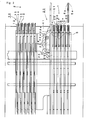
- Fig. 2 shows a structure in the vicinity of the edge of one needle bed 11 of a flatbed knitting machine equipped with the knitting yarn holding device 1 shown in Fig. 1 .
- the flatbed knitting machine 10 To the flatbed knitting machine 10, at least one pair of needle beds 11 are provided opposite to each other in the front and in the rear with the needle bed gap 2 held in-between.
- Each needle bed 11 includes a portion in which a large number of needle plates 12 are arranged in parallel at predetermined interval pitch between both ends in the width direction, which is the vertical direction in the figure.
- the spaces between needle plates 12 becomes needle grooves 13, each of which houses a knitting needle 14 respectively.
- a sinker 15 is housed in each needle groove 13, too.
- a knitting yarn holding and cutting device 20 is installed at the edge of the needle bed 11.
- the knitting yarn holding and cutting device 20 includes a plurality of knitting yarn holding devices 1 and one knitting yarn cutting device 21.
- the knitting yarn cutting device 21 has a cutter bar 22 and can move the portion of a blade 22a installed on the head end side forward and backward relative to the needle bed gap 2.
- a cutter 23 is provided on the needle bed 11 side, and when a cutter bar 22 which moves forward to the needle bed gap 2 and captures the knitting yarn 4 on the blade 22a is allowed to withdraw from the needle bed gap 2, the cutter 23 can put the knitting yarn 4 between the blade 22a and the blade 23a of the cutter 23, and can cut the knitting yarn 4.
- the cutter 23 is pressed against the cutter bar 22 from the side by a spring 24.
- the cutter bar 22 slides to move the head end forward and backward relative to the needle bed gap 2 while being clipped between the cutter 23 and a plate 25.
- a plurality of the plates 25 are erectly set up at predetermined interval pitch toward the outward of the edge of the needle bed 11.
- the plate 25 is parallel to the needle plate 12 and a guide groove 26 formed between plates 25 is parallel to the needle groove 13.
- the needle plate 12 and the plate 25 are erectly set up from a substrate 27 and fixed by a wire 11a passing through in the width direction.
- a hook bar 5 is housed in each guide groove 26 respectively.
- the plate 25 and the spacer 6 are fixed by a metal band 11b and a wire 11c, those are passing through.
- the knitting yarn cutting device 21 located at the inner side in the width direction, which is the direction between both ends of the needle bed 11 and a plurality of knitting yarn holding devices 1 located at the outside in the width direction.
- the knitting yarn holding and cutting device 20 is installed at least on one end of the needle bed 11 and is also installed on the needle bed 11 opposed with the needle bed gap 2 in-between, in the same manner.
- at least two knitting yarn holding and cutting devices 20 are, therefore, able to be installed as a whole.
- Fig. 3 shows a simplified diagrammatic overall structure for selectively driving the hook bar 5 in the flatbed knitting machine 10 shown in Fig. 2 .
- the hook bar 5 is housed in the guide groove 26 formed between the plates 25.
- the plates 25 are erectly set up at predetermined intervals on the substrate 27.
- the head end side of a jack 28 is connected to the tail-end side of the hook bar 5.
- a butt 28a is installed to the jack 28, and when the hook bar 5 is selectively driven, the butt 28a protrudes to the outside of the guide groove 26.
- Selective drive of the hook bar 5 is performed by a select jack 29 and a selector 30 in the same manner as in the case of the knitting needle 14.
- Fig. 4 shows a diagrammatic cam arrangement in a cam system 31 equipped to a carriage used for the flatbed knitting machine 10 shown in Fig. 3 .
- the cam system 31 is installed to a bottom board 32 of a carriage facing to the surface of the needle bed 11, and includes cams for knitting such as a needle raising cam 33, a bridge cam 34, stitch cams 35, and cams for slider 36.
- the butt 28a of the jack 28 guides the knitting needle along a route at the time of knitting by the use of these cams for knitting.
- the butt 28a of the jack 28 is guided in such a manner as to pass through the trajectory 38 shown by a solid line.
- the yarn feeder port 3a used for knitting, feeds the yarn at the position deviated to the left side from the center of the cam for knitting but to the knitting yarn holding and cutting device 20, the yarn is fed at the center location of the cams for knitting shown as the yarn feeder port 3 with the solid line.
- the stitch cams 35 are located at the position shown by the solid line and weakens pull-in of the hook bar 5 or the cutter bar 22 after they are moved forward relative to the needle bed gap 2.
- the stitch cams 35 are located at the position shown by the chain double-dashed line, and strengthens pull-in after the hook bar 5 and the cutter bar 22 are moved forward relative to the needle bed gap 2.
- the butt 28a of the jack 28 is guided to pass through the trajectory 39 shown by the chain double-dashed line.
- Fig. 5 shows a partial side structure of the plate 25, a planar structure of the hook bar 5 and a side structure thereof.
- a notch 25a is provided on the head end side of the plate 25, a notch 25a is provided and enables a spacer 6 to be attached to a pressing plate 7.
- a hole for insertion 25b to insert a metal band 11b together with a spacer 6 and to fix them as in Fig. 3 is provided, too.
- the hook bar 5 has the cam groove 5c formed on the head end side, and furthermore, the hook 5a and the latching stop part 5b are divided into a forked shape.
- Fig. 6 shows a side structure and a front structure of the spacer 6 used for the knitting yarn holding device 1 of Fig. 1 and a planar structure and a side structure of the pressing plate 7.
- the elastic leg 6a is extended from the spacer 6, and under a free state as shown in Fig. 1(f) , the elastic leg 6a has the lower-limit form shown by the solid line.
- the elastic leg elastically deforms and attains the upper limit state.
- Fig. 6 shows a side structure and a front structure of the spacer 6 used for the knitting yarn holding device 1 of Fig. 1 and a planar structure and a side structure of the pressing plate 7.
- the elastic leg 6a has thinner thickness at the follower part 6c and the guiding part 6d, and fitted into the cam groove 5c of the hook bar 5 shown in Fig. 5(b) .
- the pressing plate 7 shown in Fig. 6 (c) and (d) is mounted to the left side of the front of the spacer 6 shown in Fig. 6(b) in the condition with the developed shape of Fig. 6(d) which is folded as shown in Fig. 6(c) .
- the pressing plate 7 in the condition with the developed shape of Fig. 6(d) is folded symmetrical to Fig. 6(c) is mounted to the right side of the spacer 6 shown in Fig. 6(c) .
- the pressing plate 7 is mounted to the spacer 6 by fastening pins into fixing holes 6e and 7a.
- a hole for insertion 6f to insert and to fix the metal band 11b together with the plate 25 in Fig. 3 is installed, too.
- the elastic leg 6a which is integrated with the spacer 6 and is extended to the needle bed gap 2 side is deformed by a cam to allow the depressing part 6b to work on the knitting yarn 4, but a pressing member that corresponds to the elastic leg 6a may be and installed in a divided state.
- the pressing member may have the head end of the member which bends at joints to press the knitting yarn 4, not by elastic deformation but by swing displacement of a lever or the like.
Landscapes
- Engineering & Computer Science (AREA)
- Textile Engineering (AREA)
- Knitting Machines (AREA)
- Braiding, Manufacturing Of Bobbin-Net Or Lace, And Manufacturing Of Nets By Knotting (AREA)
Applications Claiming Priority (1)
| Application Number | Priority Date | Filing Date | Title |
|---|---|---|---|
| JP2010026644A JP5637698B2 (ja) | 2010-02-09 | 2010-02-09 | 横編機の編糸保持装置 |
Publications (2)
| Publication Number | Publication Date |
|---|---|
| EP2354285A1 true EP2354285A1 (fr) | 2011-08-10 |
| EP2354285B1 EP2354285B1 (fr) | 2014-11-12 |
Family
ID=43859704
Family Applications (1)
| Application Number | Title | Priority Date | Filing Date |
|---|---|---|---|
| EP11001055.0A Active EP2354285B1 (fr) | 2010-02-09 | 2011-02-09 | Dispositif de manipulation de fil à tricoter pour machine à tricoter à plat |
Country Status (3)
| Country | Link |
|---|---|
| EP (1) | EP2354285B1 (fr) |
| JP (1) | JP5637698B2 (fr) |
| CN (1) | CN102146613B (fr) |
Cited By (1)
| Publication number | Priority date | Publication date | Assignee | Title |
|---|---|---|---|---|
| US20150013393A1 (en) * | 2013-07-10 | 2015-01-15 | Steiger Participations Sa | Pinching and Cutting Device for a Flat Knitting Machine |
Families Citing this family (2)
| Publication number | Priority date | Publication date | Assignee | Title |
|---|---|---|---|---|
| WO2017098636A1 (fr) * | 2015-12-10 | 2017-06-15 | Ykk株式会社 | Procédé et dispositif de fabrication de bande pour fermeture à glissière tricotée |
| CN121336095A (zh) | 2023-06-19 | 2026-01-13 | 三菱电机株式会社 | 电波屏蔽结构和底盘测功机系统 |
Citations (5)
| Publication number | Priority date | Publication date | Assignee | Title |
|---|---|---|---|---|
| JPH02269848A (ja) * | 1989-04-08 | 1990-11-05 | Shima Seiki Seisakusho:Kk | 横編機における糸把持装置 |
| JPH0415973B2 (fr) | 1982-11-26 | 1992-03-19 | Hitachi Ltd | |
| JP2002302852A (ja) * | 2001-04-09 | 2002-10-18 | Matsutani Tekko:Kk | 横編機における端糸の処理装置及びその処理方法 |
| KR20050014665A (ko) * | 2003-07-30 | 2005-02-07 | 가부시키가이샤 시마세이키 세이사쿠쇼 | 편사의 지지절단 방법 및 장치 |
| EP1847639A1 (fr) * | 2006-04-21 | 2007-10-24 | H. Stoll GmbH & Co. KG | Platine coupe fil d'une machine à tricoter à fontures rectilignes |
-
2010
- 2010-02-09 JP JP2010026644A patent/JP5637698B2/ja active Active
-
2011
- 2011-01-20 CN CN201110022271.3A patent/CN102146613B/zh active Active
- 2011-02-09 EP EP11001055.0A patent/EP2354285B1/fr active Active
Patent Citations (6)
| Publication number | Priority date | Publication date | Assignee | Title |
|---|---|---|---|---|
| JPH0415973B2 (fr) | 1982-11-26 | 1992-03-19 | Hitachi Ltd | |
| JPH02269848A (ja) * | 1989-04-08 | 1990-11-05 | Shima Seiki Seisakusho:Kk | 横編機における糸把持装置 |
| JP2002302852A (ja) * | 2001-04-09 | 2002-10-18 | Matsutani Tekko:Kk | 横編機における端糸の処理装置及びその処理方法 |
| KR20050014665A (ko) * | 2003-07-30 | 2005-02-07 | 가부시키가이샤 시마세이키 세이사쿠쇼 | 편사의 지지절단 방법 및 장치 |
| JP4015973B2 (ja) * | 2003-07-30 | 2007-11-28 | 株式会社島精機製作所 | 編糸保持切断方法および装置 |
| EP1847639A1 (fr) * | 2006-04-21 | 2007-10-24 | H. Stoll GmbH & Co. KG | Platine coupe fil d'une machine à tricoter à fontures rectilignes |
Cited By (2)
| Publication number | Priority date | Publication date | Assignee | Title |
|---|---|---|---|---|
| US20150013393A1 (en) * | 2013-07-10 | 2015-01-15 | Steiger Participations Sa | Pinching and Cutting Device for a Flat Knitting Machine |
| EP2824227B1 (fr) * | 2013-07-10 | 2019-01-02 | Steiger Participations SA | Dispositif de pincement et de coupe pour une machine à tricoter rectiligne |
Also Published As
| Publication number | Publication date |
|---|---|
| JP2011162912A (ja) | 2011-08-25 |
| CN102146613B (zh) | 2014-09-24 |
| EP2354285B1 (fr) | 2014-11-12 |
| CN102146613A (zh) | 2011-08-10 |
| JP5637698B2 (ja) | 2014-12-10 |
Similar Documents
| Publication | Publication Date | Title |
|---|---|---|
| EP2038460B1 (fr) | Métier à tricoter avec aiguilles à clapet et sans platines | |
| CN103180500B (zh) | 尤其是具有高织针号的针织机 | |
| EP2196569B1 (fr) | Métier à mailles cueillies | |
| CN106521821B (zh) | 缝纫机的压脚 | |
| EP2894245B1 (fr) | Machine à tricoter rectiligne équipé d'une dispositif de platine | |
| EP2354285B1 (fr) | Dispositif de manipulation de fil à tricoter pour machine à tricoter à plat | |
| CN101148802B (zh) | 横机的沉降片装置和导纱隔距块 | |
| KR20080031818A (ko) | 터프팅 기계용 파지기 | |
| CN109183263B (zh) | 一种电脑横机针织机构及方法 | |
| EP2423363B1 (fr) | Metier a mailles cueillies equipe d'une platine mobile | |
| EP2397589B1 (fr) | Aiguille de type compound pour les machines à tricoter rectiligne | |
| EP1731648B1 (fr) | Dispositif à platine cueillante mobile et platine cueillante de machine à tricoter à trame | |
| KR19990028846A (ko) | 횡편기에 있어서의 실안내장치 | |
| CN101278086B (zh) | 具有可动导纱器的横机 | |
| EP2415917B1 (fr) | Aiguille de type compound pour machine à tricoter rectiligne | |
| EP3156530B1 (fr) | Dispositif d'installation | |
| TWI444516B (zh) | 梭車刺繡機 | |
| EP2372003A1 (fr) | Dispositif de came pour aiguille de réception de transfert | |
| JP4519636B2 (ja) | 可動シンカを備える横編機 | |
| US10968989B2 (en) | Chain guide | |
| JP2009114564A (ja) | 横編機 | |
| EP4455379A1 (fr) | Machine à tricoter rectiligne | |
| WO2017098636A1 (fr) | Procédé et dispositif de fabrication de bande pour fermeture à glissière tricotée | |
| JP2004057677A (ja) | ミシン用押え金 | |
| JPS5929978Y2 (ja) | 手編機の選針板等支持案内装置 |
Legal Events
| Date | Code | Title | Description |
|---|---|---|---|
| PUAI | Public reference made under article 153(3) epc to a published international application that has entered the european phase |
Free format text: ORIGINAL CODE: 0009012 |
|
| AK | Designated contracting states |
Kind code of ref document: A1 Designated state(s): AL AT BE BG CH CY CZ DE DK EE ES FI FR GB GR HR HU IE IS IT LI LT LU LV MC MK MT NL NO PL PT RO RS SE SI SK SM TR |
|
| AX | Request for extension of the european patent |
Extension state: BA ME |
|
| 17P | Request for examination filed |
Effective date: 20120119 |
|
| RIC1 | Information provided on ipc code assigned before grant |
Ipc: D04B 15/00 20060101AFI20140404BHEP Ipc: D04B 15/56 20060101ALI20140404BHEP |
|
| GRAP | Despatch of communication of intention to grant a patent |
Free format text: ORIGINAL CODE: EPIDOSNIGR1 |
|
| INTG | Intention to grant announced |
Effective date: 20140516 |
|
| GRAS | Grant fee paid |
Free format text: ORIGINAL CODE: EPIDOSNIGR3 |
|
| GRAA | (expected) grant |
Free format text: ORIGINAL CODE: 0009210 |
|
| AK | Designated contracting states |
Kind code of ref document: B1 Designated state(s): AL AT BE BG CH CY CZ DE DK EE ES FI FR GB GR HR HU IE IS IT LI LT LU LV MC MK MT NL NO PL PT RO RS SE SI SK SM TR |
|
| REG | Reference to a national code |
Ref country code: GB Ref legal event code: FG4D |
|
| REG | Reference to a national code |
Ref country code: CH Ref legal event code: EP |
|
| REG | Reference to a national code |
Ref country code: AT Ref legal event code: REF Ref document number: 695843 Country of ref document: AT Kind code of ref document: T Effective date: 20141115 |
|
| REG | Reference to a national code |
Ref country code: IE Ref legal event code: FG4D |
|
| REG | Reference to a national code |
Ref country code: DE Ref legal event code: R096 Ref document number: 602011011219 Country of ref document: DE Effective date: 20141224 |
|
| REG | Reference to a national code |
Ref country code: NL Ref legal event code: VDEP Effective date: 20141112 |
|
| REG | Reference to a national code |
Ref country code: AT Ref legal event code: MK05 Ref document number: 695843 Country of ref document: AT Kind code of ref document: T Effective date: 20141112 |
|
| PG25 | Lapsed in a contracting state [announced via postgrant information from national office to epo] |
Ref country code: IS Free format text: LAPSE BECAUSE OF FAILURE TO SUBMIT A TRANSLATION OF THE DESCRIPTION OR TO PAY THE FEE WITHIN THE PRESCRIBED TIME-LIMIT Effective date: 20150312 Ref country code: PT Free format text: LAPSE BECAUSE OF FAILURE TO SUBMIT A TRANSLATION OF THE DESCRIPTION OR TO PAY THE FEE WITHIN THE PRESCRIBED TIME-LIMIT Effective date: 20150312 Ref country code: NL Free format text: LAPSE BECAUSE OF FAILURE TO SUBMIT A TRANSLATION OF THE DESCRIPTION OR TO PAY THE FEE WITHIN THE PRESCRIBED TIME-LIMIT Effective date: 20141112 Ref country code: LT Free format text: LAPSE BECAUSE OF FAILURE TO SUBMIT A TRANSLATION OF THE DESCRIPTION OR TO PAY THE FEE WITHIN THE PRESCRIBED TIME-LIMIT Effective date: 20141112 Ref country code: NO Free format text: LAPSE BECAUSE OF FAILURE TO SUBMIT A TRANSLATION OF THE DESCRIPTION OR TO PAY THE FEE WITHIN THE PRESCRIBED TIME-LIMIT Effective date: 20150212 Ref country code: ES Free format text: LAPSE BECAUSE OF FAILURE TO SUBMIT A TRANSLATION OF THE DESCRIPTION OR TO PAY THE FEE WITHIN THE PRESCRIBED TIME-LIMIT Effective date: 20141112 Ref country code: FI Free format text: LAPSE BECAUSE OF FAILURE TO SUBMIT A TRANSLATION OF THE DESCRIPTION OR TO PAY THE FEE WITHIN THE PRESCRIBED TIME-LIMIT Effective date: 20141112 |
|
| PG25 | Lapsed in a contracting state [announced via postgrant information from national office to epo] |
Ref country code: SE Free format text: LAPSE BECAUSE OF FAILURE TO SUBMIT A TRANSLATION OF THE DESCRIPTION OR TO PAY THE FEE WITHIN THE PRESCRIBED TIME-LIMIT Effective date: 20141112 Ref country code: PL Free format text: LAPSE BECAUSE OF FAILURE TO SUBMIT A TRANSLATION OF THE DESCRIPTION OR TO PAY THE FEE WITHIN THE PRESCRIBED TIME-LIMIT Effective date: 20141112 Ref country code: RS Free format text: LAPSE BECAUSE OF FAILURE TO SUBMIT A TRANSLATION OF THE DESCRIPTION OR TO PAY THE FEE WITHIN THE PRESCRIBED TIME-LIMIT Effective date: 20141112 Ref country code: HR Free format text: LAPSE BECAUSE OF FAILURE TO SUBMIT A TRANSLATION OF THE DESCRIPTION OR TO PAY THE FEE WITHIN THE PRESCRIBED TIME-LIMIT Effective date: 20141112 Ref country code: AT Free format text: LAPSE BECAUSE OF FAILURE TO SUBMIT A TRANSLATION OF THE DESCRIPTION OR TO PAY THE FEE WITHIN THE PRESCRIBED TIME-LIMIT Effective date: 20141112 Ref country code: CY Free format text: LAPSE BECAUSE OF FAILURE TO SUBMIT A TRANSLATION OF THE DESCRIPTION OR TO PAY THE FEE WITHIN THE PRESCRIBED TIME-LIMIT Effective date: 20141112 Ref country code: LV Free format text: LAPSE BECAUSE OF FAILURE TO SUBMIT A TRANSLATION OF THE DESCRIPTION OR TO PAY THE FEE WITHIN THE PRESCRIBED TIME-LIMIT Effective date: 20141112 Ref country code: GR Free format text: LAPSE BECAUSE OF FAILURE TO SUBMIT A TRANSLATION OF THE DESCRIPTION OR TO PAY THE FEE WITHIN THE PRESCRIBED TIME-LIMIT Effective date: 20150213 |
|
| PG25 | Lapsed in a contracting state [announced via postgrant information from national office to epo] |
Ref country code: EE Free format text: LAPSE BECAUSE OF FAILURE TO SUBMIT A TRANSLATION OF THE DESCRIPTION OR TO PAY THE FEE WITHIN THE PRESCRIBED TIME-LIMIT Effective date: 20141112 Ref country code: DK Free format text: LAPSE BECAUSE OF FAILURE TO SUBMIT A TRANSLATION OF THE DESCRIPTION OR TO PAY THE FEE WITHIN THE PRESCRIBED TIME-LIMIT Effective date: 20141112 Ref country code: CZ Free format text: LAPSE BECAUSE OF FAILURE TO SUBMIT A TRANSLATION OF THE DESCRIPTION OR TO PAY THE FEE WITHIN THE PRESCRIBED TIME-LIMIT Effective date: 20141112 Ref country code: RO Free format text: LAPSE BECAUSE OF FAILURE TO SUBMIT A TRANSLATION OF THE DESCRIPTION OR TO PAY THE FEE WITHIN THE PRESCRIBED TIME-LIMIT Effective date: 20141112 Ref country code: SK Free format text: LAPSE BECAUSE OF FAILURE TO SUBMIT A TRANSLATION OF THE DESCRIPTION OR TO PAY THE FEE WITHIN THE PRESCRIBED TIME-LIMIT Effective date: 20141112 |
|
| REG | Reference to a national code |
Ref country code: DE Ref legal event code: R097 Ref document number: 602011011219 Country of ref document: DE |
|
| PLBE | No opposition filed within time limit |
Free format text: ORIGINAL CODE: 0009261 |
|
| STAA | Information on the status of an ep patent application or granted ep patent |
Free format text: STATUS: NO OPPOSITION FILED WITHIN TIME LIMIT |
|
| PG25 | Lapsed in a contracting state [announced via postgrant information from national office to epo] |
Ref country code: LU Free format text: LAPSE BECAUSE OF FAILURE TO SUBMIT A TRANSLATION OF THE DESCRIPTION OR TO PAY THE FEE WITHIN THE PRESCRIBED TIME-LIMIT Effective date: 20150209 |
|
| REG | Reference to a national code |
Ref country code: CH Ref legal event code: PL |
|
| 26N | No opposition filed |
Effective date: 20150813 |
|
| GBPC | Gb: european patent ceased through non-payment of renewal fee |
Effective date: 20150212 |
|
| PG25 | Lapsed in a contracting state [announced via postgrant information from national office to epo] |
Ref country code: CH Free format text: LAPSE BECAUSE OF NON-PAYMENT OF DUE FEES Effective date: 20150228 Ref country code: LI Free format text: LAPSE BECAUSE OF NON-PAYMENT OF DUE FEES Effective date: 20150228 Ref country code: MC Free format text: LAPSE BECAUSE OF FAILURE TO SUBMIT A TRANSLATION OF THE DESCRIPTION OR TO PAY THE FEE WITHIN THE PRESCRIBED TIME-LIMIT Effective date: 20141112 |
|
| REG | Reference to a national code |
Ref country code: IE Ref legal event code: MM4A |
|
| REG | Reference to a national code |
Ref country code: FR Ref legal event code: ST Effective date: 20151030 |
|
| PG25 | Lapsed in a contracting state [announced via postgrant information from national office to epo] |
Ref country code: GB Free format text: LAPSE BECAUSE OF NON-PAYMENT OF DUE FEES Effective date: 20150212 Ref country code: IE Free format text: LAPSE BECAUSE OF NON-PAYMENT OF DUE FEES Effective date: 20150209 |
|
| PG25 | Lapsed in a contracting state [announced via postgrant information from national office to epo] |
Ref country code: SI Free format text: LAPSE BECAUSE OF FAILURE TO SUBMIT A TRANSLATION OF THE DESCRIPTION OR TO PAY THE FEE WITHIN THE PRESCRIBED TIME-LIMIT Effective date: 20141112 Ref country code: FR Free format text: LAPSE BECAUSE OF NON-PAYMENT OF DUE FEES Effective date: 20150302 |
|
| PG25 | Lapsed in a contracting state [announced via postgrant information from national office to epo] |
Ref country code: MT Free format text: LAPSE BECAUSE OF FAILURE TO SUBMIT A TRANSLATION OF THE DESCRIPTION OR TO PAY THE FEE WITHIN THE PRESCRIBED TIME-LIMIT Effective date: 20141112 |
|
| PG25 | Lapsed in a contracting state [announced via postgrant information from national office to epo] |
Ref country code: BG Free format text: LAPSE BECAUSE OF FAILURE TO SUBMIT A TRANSLATION OF THE DESCRIPTION OR TO PAY THE FEE WITHIN THE PRESCRIBED TIME-LIMIT Effective date: 20141112 Ref country code: HU Free format text: LAPSE BECAUSE OF FAILURE TO SUBMIT A TRANSLATION OF THE DESCRIPTION OR TO PAY THE FEE WITHIN THE PRESCRIBED TIME-LIMIT; INVALID AB INITIO Effective date: 20110209 Ref country code: SM Free format text: LAPSE BECAUSE OF FAILURE TO SUBMIT A TRANSLATION OF THE DESCRIPTION OR TO PAY THE FEE WITHIN THE PRESCRIBED TIME-LIMIT Effective date: 20141112 |
|
| PG25 | Lapsed in a contracting state [announced via postgrant information from national office to epo] |
Ref country code: TR Free format text: LAPSE BECAUSE OF FAILURE TO SUBMIT A TRANSLATION OF THE DESCRIPTION OR TO PAY THE FEE WITHIN THE PRESCRIBED TIME-LIMIT Effective date: 20141112 |
|
| PG25 | Lapsed in a contracting state [announced via postgrant information from national office to epo] |
Ref country code: BE Free format text: LAPSE BECAUSE OF FAILURE TO SUBMIT A TRANSLATION OF THE DESCRIPTION OR TO PAY THE FEE WITHIN THE PRESCRIBED TIME-LIMIT Effective date: 20141112 |
|
| PG25 | Lapsed in a contracting state [announced via postgrant information from national office to epo] |
Ref country code: MK Free format text: LAPSE BECAUSE OF FAILURE TO SUBMIT A TRANSLATION OF THE DESCRIPTION OR TO PAY THE FEE WITHIN THE PRESCRIBED TIME-LIMIT Effective date: 20141112 |
|
| PG25 | Lapsed in a contracting state [announced via postgrant information from national office to epo] |
Ref country code: AL Free format text: LAPSE BECAUSE OF FAILURE TO SUBMIT A TRANSLATION OF THE DESCRIPTION OR TO PAY THE FEE WITHIN THE PRESCRIBED TIME-LIMIT Effective date: 20141112 |
|
| PGFP | Annual fee paid to national office [announced via postgrant information from national office to epo] |
Ref country code: DE Payment date: 20251216 Year of fee payment: 16 |
|
| PGFP | Annual fee paid to national office [announced via postgrant information from national office to epo] |
Ref country code: IT Payment date: 20260122 Year of fee payment: 16 |