EP2354407A2 - Dispositif d'amortissement pour éléments de porte guidés sur rails - Google Patents
Dispositif d'amortissement pour éléments de porte guidés sur rails Download PDFInfo
- Publication number
- EP2354407A2 EP2354407A2 EP20110000652 EP11000652A EP2354407A2 EP 2354407 A2 EP2354407 A2 EP 2354407A2 EP 20110000652 EP20110000652 EP 20110000652 EP 11000652 A EP11000652 A EP 11000652A EP 2354407 A2 EP2354407 A2 EP 2354407A2
- Authority
- EP
- European Patent Office
- Prior art keywords
- damping device
- guide rail
- driver
- receiving body
- carriage
- Prior art date
- Legal status (The legal status is an assumption and is not a legal conclusion. Google has not performed a legal analysis and makes no representation as to the accuracy of the status listed.)
- Granted
Links
Images



Classifications
-
- E—FIXED CONSTRUCTIONS
- E05—LOCKS; KEYS; WINDOW OR DOOR FITTINGS; SAFES
- E05F—DEVICES FOR MOVING WINGS INTO OPEN OR CLOSED POSITION; CHECKS FOR WINGS; WING FITTINGS NOT OTHERWISE PROVIDED FOR, CONCERNED WITH THE FUNCTIONING OF THE WING
- E05F5/00—Braking devices, e.g. checks; Stops; Buffers
- E05F5/003—Braking devices, e.g. checks; Stops; Buffers for sliding wings
-
- E—FIXED CONSTRUCTIONS
- E05—LOCKS; KEYS; WINDOW OR DOOR FITTINGS; SAFES
- E05F—DEVICES FOR MOVING WINGS INTO OPEN OR CLOSED POSITION; CHECKS FOR WINGS; WING FITTINGS NOT OTHERWISE PROVIDED FOR, CONCERNED WITH THE FUNCTIONING OF THE WING
- E05F1/00—Closers or openers for wings, not otherwise provided for in this subclass
- E05F1/08—Closers or openers for wings, not otherwise provided for in this subclass spring-actuated, e.g. for horizontally sliding wings
- E05F1/16—Closers or openers for wings, not otherwise provided for in this subclass spring-actuated, e.g. for horizontally sliding wings for sliding wings
-
- E—FIXED CONSTRUCTIONS
- E05—LOCKS; KEYS; WINDOW OR DOOR FITTINGS; SAFES
- E05Y—INDEXING SCHEME ASSOCIATED WITH SUBCLASSES E05D AND E05F, RELATING TO CONSTRUCTION ELEMENTS, ELECTRIC CONTROL, POWER SUPPLY, POWER SIGNAL OR TRANSMISSION, USER INTERFACES, MOUNTING OR COUPLING, DETAILS, ACCESSORIES, AUXILIARY OPERATIONS NOT OTHERWISE PROVIDED FOR, APPLICATION THEREOF
- E05Y2201/00—Constructional elements; Accessories therefor
- E05Y2201/40—Motors; Magnets; Springs; Weights; Accessories therefor
- E05Y2201/404—Function thereof
- E05Y2201/41—Function thereof for closing
- E05Y2201/412—Function thereof for closing for the final closing movement
-
- E—FIXED CONSTRUCTIONS
- E05—LOCKS; KEYS; WINDOW OR DOOR FITTINGS; SAFES
- E05Y—INDEXING SCHEME ASSOCIATED WITH SUBCLASSES E05D AND E05F, RELATING TO CONSTRUCTION ELEMENTS, ELECTRIC CONTROL, POWER SUPPLY, POWER SIGNAL OR TRANSMISSION, USER INTERFACES, MOUNTING OR COUPLING, DETAILS, ACCESSORIES, AUXILIARY OPERATIONS NOT OTHERWISE PROVIDED FOR, APPLICATION THEREOF
- E05Y2201/00—Constructional elements; Accessories therefor
- E05Y2201/60—Suspension or transmission members; Accessories therefor
- E05Y2201/622—Suspension or transmission members elements
- E05Y2201/684—Rails; Tracks
-
- E—FIXED CONSTRUCTIONS
- E05—LOCKS; KEYS; WINDOW OR DOOR FITTINGS; SAFES
- E05Y—INDEXING SCHEME ASSOCIATED WITH SUBCLASSES E05D AND E05F, RELATING TO CONSTRUCTION ELEMENTS, ELECTRIC CONTROL, POWER SUPPLY, POWER SIGNAL OR TRANSMISSION, USER INTERFACES, MOUNTING OR COUPLING, DETAILS, ACCESSORIES, AUXILIARY OPERATIONS NOT OTHERWISE PROVIDED FOR, APPLICATION THEREOF
- E05Y2800/00—Details, accessories and auxiliary operations not otherwise provided for
- E05Y2800/20—Combinations of elements
- E05Y2800/23—Combinations of elements of elements of different categories
- E05Y2800/24—Combinations of elements of elements of different categories of springs and brakes
-
- E—FIXED CONSTRUCTIONS
- E05—LOCKS; KEYS; WINDOW OR DOOR FITTINGS; SAFES
- E05Y—INDEXING SCHEME ASSOCIATED WITH SUBCLASSES E05D AND E05F, RELATING TO CONSTRUCTION ELEMENTS, ELECTRIC CONTROL, POWER SUPPLY, POWER SIGNAL OR TRANSMISSION, USER INTERFACES, MOUNTING OR COUPLING, DETAILS, ACCESSORIES, AUXILIARY OPERATIONS NOT OTHERWISE PROVIDED FOR, APPLICATION THEREOF
- E05Y2800/00—Details, accessories and auxiliary operations not otherwise provided for
- E05Y2800/26—Form or shape
- E05Y2800/28—Form or shape tubular, annular
Definitions
- the invention relates to a damping device for rail-guided door elements, in particular for single or double-leaf sliding doors, which are supported by at least one carriage with rollers on at least one guide rail, wherein a damping element is provided for braking.
- Generic damping devices are equipped with a damping element, so that the opening or closing door elements can be braked.
- These may be, for example, moving sliding doors, which are held by one or more carriages and guided within a rail, for example, sliding doors for furniture parts.
- sliding doors which are intended for the separation of rooms, usually large-sized and heavy-weight door elements are used, so that the dimensions of the guide rail, the carriage and the damping element must be designed accordingly.
- a slide which has a plurality of rollers, which are movable in the guide rail along the longitudinal direction. Due to the large weight and the existing mass of the individual door elements a deceleration is required so that the door elements can not start against a stop with a significant kinetic energy.
- damping elements in this case primarily piston cylinder systems are used, by which a door element are braked when rising or running against a stop or the end of the guide rail. In most cases, when the door element rises or falls, there is direct contact with a piston rod which dips into an existing cylinder and triggers the deceleration process.
- damping elements are designed very long construction and must be mounted in the longitudinal direction of the guide rail become.
- the opening width of a door opening is limited on the one hand and on the other hand, an installation space required that does not meet all local installation conditions.
- the object of the present invention is to show a novel damping device, which eliminates the existing disadvantages of the art and allows quick installation for retrofitting.
- a receiving body is used for fastening the damping element, having an opening into which the carriage is formed retractable. Further advantageous embodiments of the invention can be taken from the subclaims.
- the damping device according to the invention offers the possibility that it can be inserted into the guide rail and secured in any position, wherein the carriage is movable into the receiving body.
- the damping device can be installed in any desired position, so that the Opening width of the door elements is limited.
- the assembly of the damping device is substantially simplified because it only needs to be positioned exactly in the longitudinal direction of the guide rail to set the closing or opening position in single-leaf door elements or the opening or closing position of the door elements in two-leaf relatively movable door elements to adjust exactly ,
- the receiving body may be rectangular, round or oval and thus can be made to adapt to the various guide rails. Due to the shape of the receiving body thus the damping device can be used for all common guide rails, in principle, the other components of the damping device, such as damping element can be installed in a corresponding manner in the receiving body. All of the embodiments provide in this case that a carriage, which rests against the guide rails, for example, is guided within the guide rail or above the guide rail, can run into the receiving body insofar as a deceleration of the door elements takes place, the respective carriage shape up to an end position is pulled by an existing spring.
- the receiving body in a first embodiment of a housing for the damping element and two fixed side panels, which are formed in the guide rail inserted and fixed.
- the side parts can in this case be screwed to the housing, welded or optionally fastened by means of clip technology and are further stabilized sufficiently by the guide rail to to allow a guide for the piston rod with driver, wherein a carriage is movable between the side panels.
- the receiving body used in this case may be U-shaped in cross-section, wherein the dimensions are selected in such a way that the receiving body is designed to be inserted into the guide rail.
- the receiving body can be inserted into the end of the guide rail in this and fixed in a predetermined position.
- a further embodiment of the receiving body consists of a U-profile, which is formed with the open side downwards in the guide rail inserted and fixed.
- the receiving body consists of a U-profile, which has a shortened in the longitudinal extension base and aligned with the open side upwards in the guide rail and is designed to be fixed, the shortened base end is arranged to the guide rail ,
- the middle part for connecting the two U-legs is referred to in this case, which according to the invention does not extend over the entire length of the receiving body, but only over a certain portion, preferably over the portion which is used to hold the damping element while the opposite section is provided for retracting the carriage.
- This embodiment of the receiving body also allows insertion of the receiving body in the guide rail with simultaneous Ensuring that the carriage within the guide rail is still traversable by means of the rollers, until the carriage within the receiving body comes into contact with the damping element and has reached its end position.
- Such receiving body designed in this case are inexpensive to manufacture and significantly reduce the manufacturing cost of the damping device according to the invention.
- the receiving body are also suitable in different profile variations, such as round, square or oval guide rails to be used.
- the receiving body is further achieved that a secure attachment of the damping element can be carried out, which can be partially inserted with one end into the receiving body and connected to them.
- the fact that the receiving body is inserted into the guide rail it is ensured at the same time that the moving parts of the damping device are arranged within the guide rail and thus are not susceptible to interference and protected from possible damage due to careless handling.
- the damping element consists of a cylinder with a piston rod to which a driver is attached. Cylinder and piston rod are thus part of the damping element, wherein the piston rod is sealingly guided in the cylinder, so that a deceleration can take place by the resulting compression pressure. About the driver is further ensured that the tarnishing against the door stop door is not only braked, but also forced by the driver is brought into an end position.
- the damping element with a spring equipped, which is connected at one end to the cylinder, housing or receiving body and the other end to the driver or the piston rod.
- the spring in this case allows a return of the piston rods within the damping element in a position corresponding to the simultaneous end position of the door element.
- the spring here ensures that the piston rod of the damping element is retracted due to the existing spring force in the cylinder, at the same time by a coupling of the door element this is pulled into the end position.
- the piston rod is pulled out of the cylinder and fixed in a locking position on the driver against the spring force of the existing spring, which can be left only by emeutes emergence of the door element.
- the aforementioned design of the damping device thus enables not only the deceleration of an up or tapered door element by the damping element, but also the forced movement of the door element in an end position, wherein the damping element is responsible for deceleration taking into account the restoring force of the spring.
- the driver or a free end of the piston rod is guided with at least two guide pins in a slotted guide of the receiving body, which has a latching position in a direction diametrically opposite to the damping element.
- the latching position corresponds to the position in which there is a separation between the driver and the door element and, in addition, the piston is fixed by the provided latching, so that the spring can not retract the piston rod into the cylinder. Only by emergence of the door element with simultaneous production of a connection between the door element and driver the latching position can be left.
- a lying outside of the guide rail part of the driver is provided for mounting hardware components.
- the driver can in this case be constructed so that it is completely arranged in the receiving body and thus installed concealed lying.
- the driver can project outwardly from the guide rail to produce a detachable connection with other fasteners of the door element. This will always be the case when the rollers are not stored within the guide rail, but for example above the guide rail and the door element to be moved is mounted below the guide rail hanging.
- a entrainment of the door element attachment is preferably provided on the driver.
- the driver may have a trough-shaped depression into which a hole of the door element attachment engages and, when lifting the driver, for example in a slotted guide, allows separation.
- the various types of fastening for the door elements namely with carriage and rollers, both within the guide rail and above the guide rail arranged invoice, so that all variants of the door element attachment can be used with the damping device according to the invention.
- the operation of the damping device consists in the fact that the driver is provided for receiving a corresponding latching element of the carriage or a door element, wherein a running against the damping element carriage pushes the driver from the latching position and is decelerated by the damping element until the end position is reached and wherein a carriage running away from the damping element moves the carrier against a spring force to the latching position and in this position the driver and the latching element are separated from each other.
- the damping device according to the invention combines a compact design, which is einschiebar advantageously in the guide rail and in this festlegbar, so that a dirt insensitivity and low susceptibility is ensured.
- a deceleration of the up or tapered door element by the damping device according to the invention, but also to ensure that the door element can be moved to an end position with a recurrent end position.
- This embodiment is preferably used wherever door elements, in particular with a higher weight, require a required deceleration and, moreover, it is ensured that they can be raised to a predetermined end position.
- a subsequent adjustment can take place after the pre-assembly of the damping device, so that the exact position of the door elements, in the open or closed position at any time, can be readjusted due to the selected arrangement.
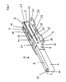
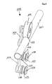
- FIG. 1 shows a perspective view of a damping device 1, which consists of a receiving body 2 and a partially located in the receiving body 2 damping element 3. Furthermore, in this perspective view of a carriage 4 recognizable, which in the receiving body 2 that is retracted in the end position.
- the receiving body 2 consists in the illustrated embodiment of a housing 7, which is connected to two side parts 5, 6.
- the side parts 5, 6 are not completely apparent from this view, However, from the following drawing figures.
- the side parts 5, 6 are laterally connected to the housing 7 and form up and down an opening into which a carriage 4 can completely retract into the receiving body 2.
- the attachment of the side parts 5, 6 takes place in the embodiment by integrally formed pins 8, 9, to which the side parts 5, 6 are clipped. Alternatively, a screw fastening can be provided.
- the damping element 3 is arranged, which consists of a cylinder with piston rod.
- the damping element 3 rests here in the box-shaped housing 7, which is inserted and fixed in the receiving body 2.
- a nut 11 is secured in a hexagonal recess 10, in which a threaded pin 12 is screwed, which allows a screw with the guide rail, not shown, so that a precise positioning of the damping device 1 can be made.
- the in FIG. 1 illustrated slide 4 consists of a cross-shaped central portion 13 to the laterally fitting pairs of rollers 14, 15 and 16, 17 are rotatably mounted.
- the middle part 13 is formed cross-shaped in the plan view and kept flat in a side view, approximately rectangular, to receive the rollers 14, 15, 16, 17.
- the cross-shaped central part 13 has a threaded bore 18 into which a screw bolt 19 is screwed, which is used for fastening a suspension 20.
- the suspension 20 in turn has a series of holes 21 which are provided for attachment to a door elements.
- the door elements can be bolted to the suspension 20 and after Mounting on the bolt 19 are fixed to the cross-shaped central portion 13 of the carriage 4.
- the type of construction allows this height compensation using the bolt 19, depending on how far he is screwed into the threaded hole 18.
- a door element not shown, in a horizontal position.
- at least two slides 4 with rollers 14, 15, 16, 17 are used, so that heavyweight door elements along the guide rail are movable and at the same time it is ensured that they are held in a vertical position.
- the slotted guide 22 has a slot running in the longitudinal direction, which has a latching position 23 on the side facing away from the damping element 3.
- the latching position 23 is determined by an end-bowing of the slotted guide 22.
- the piston rod of the damping element 3 has at its free end a driver 24, which in each case has two lateral guide pins 25.
- the guide pins 25 rest in the slide guide 22, so that the piston rod and the driver 24 can follow a horizontal movement of the carriage 4 until the latching position 23 is reached.
- the driver 24 is used for connection to the carriage 4 via a corresponding latching element, which is provided for receiving the driver 24
- the solution according to the invention provides that the latching element and the catch 24 are separated from one another upon reaching the latching position 23, so that the door element can continue to move until the door is completely opened or closed, while the catch 24 with its guide pins 25 in FIG the latching position 23 remains.
- the carriage 4 thus runs against the damping device 1, namely until the driver 24 and the Are latching element connected, at the same time the driver 24 is raised and the guide pin 25 are lifted from the latching position 23, so that in the further by an unrecognizable spring, the piston rod with driver 24 and thus simultaneously pulled along with the carriage 4 in an end position. This process is repeated when the door elements are moved to a closed or open position.
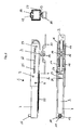
- FIG. 2 shows the off FIG. 1 known embodiment of the damping device 1 in a side view and a plan view. From the side view, the position of the carriage 4 within the receiving body 2 can be seen, wherein below the carriage 4, the suspension 20 is fastened by means of a screw bolt 19. The suspension 20 is used to screw on the door elements and can be adjusted via the mounting bolts 19 in height. At the other end is the housing 7 of the damping element 3, which is partially inserted into the receiving body 2 and connected by means of the pins 8, 9. From the plan view again the position of the damping element 3 within the housing 7 can be seen, with the piston rod 26 and driver 24. The carriage 4 with a cross-shaped central portion 13 and the end paired rollers 14, 15, 16, 17 rests within the Receiving body 3, as already out FIG. 1 seen.
- FIG. 27 Another side view, namely in the direction of a guide rail 27 discloses the exact position of the damping device 1 within the guide rail 27.
- the guide rail 27 has a nearly square cross-section, which is designed to be open at the bottom and the two legs are executed cranked, while in the upper region of the guide rail 27, a trapezoidal increase 28 is formed.
- the suspension 20, which is connected via a bolt 19 with the carriage 4 can be seen, so again it is clear that the suspension 20 is disposed below the guide rail 27 and the Assembly of unillustrated door elements can be used.
- the height adjustment, ie orientation of the door elements can in this case be done with the help of the bolts 19, since this is carried out in the cruciform central portion 13 of the carriage 4 in height variably screwed.
- a threaded pin 12 rests within a nut 11, which is already apparent from the plan view and can be screwed to fix the damping device 1 in such a way that a tension with the trapezoidal increase 28 of the guide rail 27 takes place.
- the damping device 1 can be mounted in any position of the guide rail 27 and also allows an exact positioning and later night adjustment if necessary.
- most of the damping device 1 rests within the guide rail 27, wherein the carriage 4 can completely retract into the receiving body 2, so that a substantial shortening of the overall length of the damping device 1 is possible.
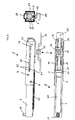
- FIG. 3 shows in a side view and plan view of the damping device 1 according to FIG. 1 and the carriage 4 with rollers 14, 15, 16, 17. Both the damping device 1 and the carriage 4 are shown here without guide rail and door element.
- the carriage 4 is located in a position in front of the damping device 1, that is, in an example approaching position against the damping device 1. From the damping device 1 from this view, the damping element 3 with threaded pin 12 and the receiving body 2 with slide guide 22 apparent. From the top view, the position of the driver 24 with guide pin 25 can be seen, wherein the piston rod 26 is opposite the cylinder 30 in an extended position.
- the driver 24 consists for example of a U-shaped bent portion, which is arranged transversely to the piston rod 26 and on both sides of the two paired guide pin 25 has.
- the existing depression of the driver 24 is further provided to receive a fishing hook 31, which integrally formed or optionally screwed to the cross-shaped central portion 13 of the carriage 4.
- the carriage 4 is equipped with the suspension 20, which is screwed via a threaded bolt 19 into a threaded bore 18 of the central part 13.
- the suspension 20 serves to fasten the door elements, wherein two carriages 4 are usually provided for a door element.
- FIG. 4 shows in a side view and plan view of the damping device 1 with carriage 4 in a retracted position of the carriage 4 within the damping device 1.
- the carriage 4 has reached its end position.
- the driver 24 is pulled with catch hook 31 and thus the carriage 4 in the end position after a deceleration of the carriage 4 is carried out by the cylinder 30 with piston rod 26.
- the guide rail 27 with a rectangular cross-section and a rise 28 can be seen, wherein the receiving body 2 has been inserted into the guide rail 27 and end braced by means of the threaded pin 12.
- the sectional view shows a section in the amount of the piston 30, so that the threaded pin 12 is not visible. From this sectional view, it will be seen below how, with the aid of a screw bolt 19, the suspension 20 is fastened to the middle part of the carriage 4 and the side parts 5, 6 of the housing 7 are inserted in the cranked guide rail 27.
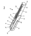
- FIG. 5 again shows the damping device 1 according to the invention in a perspective bottom view.
- FIG. 6 shows in a perspective side view of another embodiment of a damping device 100, which is provided for a round guide rail 127.
- a roller 114 is arranged, which has a convex curvature 133, which is adapted to the radius of the guide rail 127.
- the roller 114 in this case carries the total load of a door element, not shown, wherein preferably at least two such carriages 104 are used.
- the damping device 100 is arranged, which is apparent from the following figures.
- Below the guide rail 127 is located in the vertical extension of the carriage 104, a support arm 134, which is equipped with two fastening bolts 135,136.
- the fastening bolts 135, 136 each have two fastening disks 137, which are used with the aid of a screw bolt 138 for fastening a door element, not shown.
- the bolt 138 is unscrewed and removed the outer mounting plate 137, so that the door element with a corresponding receiving bore can be hung in a double arrangement on the middle part 139 of the fastening bolts 135,136, to then allow a secure attachment of the door element with the carriage 104 after screwing.
- FIG. 7 shows in a perspective, partially sectional view of the damping device 100 according to FIG. 6 , wherein from this illustration, an identical structure can be seen, but it becomes clear how the arrangement of the damping device 100 takes place within the guide rail 127.
- the damping device 100 also has a receiving body 102 by a damping element 103 is arranged, which can be withdrawn by means of a spring 132 in the existing cylinder.
- the receiving body 102 as he in particular FIG. 9 is again clearly visible, is executed in this case round and has a forked end with two legs 102a, 102b.
- a portion of the carriage 104 is arranged to be movable in the longitudinal direction, which is in particular a driver 124 of the carriage 104.
- the driver 124 is also guided in a slide guide 122 and with laterally molded guide pin 125.
- the slide guide 122 also has a latching position 123, in which the guide pin 125 can engage. Similar to the solution described above, the guide pins 125 are pushed out of the latching position 123 by the ascending carriage 104, so that the spring 124 retracts the catch 124 to an end position.
- a deceleration by the damping element 103 initially takes place in order to prevent uncontrolled opening or closing of the door element, wherein a defined end position is achieved by the spring 132.
- FIG. 8 shows a side view of the damping device 100 with roller 114, guide rail 127 and the in-guide rail 127 receiving body 102, which in the further for receiving the damping element 103, the spring 132 and a driver 124 is provided.
- the driver 124 has a vertical extension 140, as shown in particular from FIG. 9 is again apparent.
- the vertical extension 140 encloses here with a round recess 143 a bolt 144 which is fixed by means of two screw-fastening plates 142.
- the determination takes place here with the support arm 134.
- the carriage 104 is first braked with a door element fastened thereto, but not shown, and then pulled into an end position.
- FIG. 9 shows in a perspective detailed view of the receiving body 102 with damping element 103 and spring 132, and the driver 124.
- the driver 124 is guided by means of two guide pins 125, which are not apparent from this view, in a slotted guide 122, which as in the first embodiment has a latching position 123.
- the slotted guide is formed within the receiving body 102, that is, it is a groove in which the guide pins 125 are guided on both sides until they are in the latching position 123 and can be pushed out of this position by a running carriage 104 , so that with the aid of the spring 132 a return of the carriage 104 can take place in an end position.
- the driver 124 has a round recess 143, in which a bolt 144 comes to rest, so that the carriage 104, not shown, can be moved by the driver 124 in the longitudinal direction.
- the spring 132 is above the damping element 103 in the receiving body 102 and is connected at one end to the damping element 103 and the other end with a spring receptacle 141 so that the spring force can retract the driver 124, provided that the guide pin 125 is not in the latching position 123 eino ,
- the driver 124 is raised in the amount of the latching position by the slide guide 122 upwards, so that the bolt 144 of Slider 104 can slide out of the recess 143.
- the driver 124 With re-emergence of the carriage 104 against the damping device 100, the driver 124 is simultaneously pushed out of the latching position 123, whereby the driver 124 is moved vertically downwards and thus a connection between carriage 104, in particular the bolt 144 and the trough-shaped recess 143rd can be done. Thus, with the aid of the driver 124, the carriage 104 can be retracted to the end position.
- the driver 124 When closing or emergence of the door elements takes place at the level of the latching position 123 in this case a separation between driver 124 and bolt 144 so that the door elements can move freely.
Landscapes
- Support Devices For Sliding Doors (AREA)
Priority Applications (1)
| Application Number | Priority Date | Filing Date | Title |
|---|---|---|---|
| PL11000652T PL2354407T3 (pl) | 2010-02-05 | 2011-01-27 | Tłumik do elementów dmvi z prowadzeniem szynowym |
Applications Claiming Priority (1)
| Application Number | Priority Date | Filing Date | Title |
|---|---|---|---|
| DE102010007128A DE102010007128B4 (de) | 2010-02-05 | 2010-02-05 | Dämpfungseinrichtung für schienengeführte Türelemente sowie Verwendung einer derartigen Dämpfungseinrichtung |
Publications (3)
| Publication Number | Publication Date |
|---|---|
| EP2354407A2 true EP2354407A2 (fr) | 2011-08-10 |
| EP2354407A3 EP2354407A3 (fr) | 2012-02-22 |
| EP2354407B1 EP2354407B1 (fr) | 2016-10-19 |
Family
ID=44062266
Family Applications (1)
| Application Number | Title | Priority Date | Filing Date |
|---|---|---|---|
| EP11000652.5A Active EP2354407B1 (fr) | 2010-02-05 | 2011-01-27 | Dispositif d'amortissement pour éléments de porte guidés sur rails |
Country Status (3)
| Country | Link |
|---|---|
| EP (1) | EP2354407B1 (fr) |
| DE (1) | DE102010007128B4 (fr) |
| PL (1) | PL2354407T3 (fr) |
Cited By (3)
| Publication number | Priority date | Publication date | Assignee | Title |
|---|---|---|---|---|
| WO2014169771A1 (fr) * | 2013-04-15 | 2014-10-23 | Xu Jiangde | Dispositif de roue supérieure anti-rebondissement à amortissement à double tuyau |
| CN105452586A (zh) * | 2014-04-08 | 2016-03-30 | 中山市欧派克五金制品有限公司 | 双管阻尼防跳上轮装置 |
| CN108442837A (zh) * | 2018-04-02 | 2018-08-24 | 中山市茵瑟特智能科技有限公司 | 移门导向器 |
Families Citing this family (2)
| Publication number | Priority date | Publication date | Assignee | Title |
|---|---|---|---|---|
| DE102012009500B4 (de) | 2012-05-14 | 2018-05-03 | Abp Beyerle Gmbh | Schiebetür |
| CN107246198B (zh) * | 2017-07-11 | 2019-04-19 | 伍志勇 | 一种家具静音缓冲结构 |
Family Cites Families (7)
| Publication number | Priority date | Publication date | Assignee | Title |
|---|---|---|---|---|
| DE8517253U1 (de) * | 1985-06-13 | 1985-07-18 | Geze Gmbh, 7250 Leonberg | Anschlagglied zur Bewegungsbegrenzung von Schiebetüren |
| JP4104739B2 (ja) * | 1998-08-20 | 2008-06-18 | 株式会社大井製作所 | スライドドアの全開チェック機構 |
| JP2008057259A (ja) * | 2006-08-31 | 2008-03-13 | Shimodaira:Kk | 戸閉具及び引戸の戸閉装置 |
| DE202007009649U1 (de) * | 2007-07-10 | 2008-11-20 | Hettich-Heinze Gmbh & Co. Kg | Führungsanordnung für ein Schiebeelement |
| ITMI20070337U1 (it) * | 2007-10-10 | 2009-04-11 | Terno Scorrevoli Srl | Dispositivo di arresto ammortizzato per ante e porte scorrevoli |
| ITMI20072168A1 (it) * | 2007-11-14 | 2009-05-15 | Agostino Ferrari Spa | "sistema di chiusura controllata per elementi scorrevoli di mobilio" |
| ITRM20080320A1 (it) * | 2008-06-18 | 2009-12-19 | Sliding S R L | Dispositivo di richiamo e smorzamento per porte scorrevoli, cassetti e similari |
-
2010
- 2010-02-05 DE DE102010007128A patent/DE102010007128B4/de active Active
-
2011
- 2011-01-27 PL PL11000652T patent/PL2354407T3/pl unknown
- 2011-01-27 EP EP11000652.5A patent/EP2354407B1/fr active Active
Non-Patent Citations (1)
| Title |
|---|
| None |
Cited By (6)
| Publication number | Priority date | Publication date | Assignee | Title |
|---|---|---|---|---|
| WO2014169771A1 (fr) * | 2013-04-15 | 2014-10-23 | Xu Jiangde | Dispositif de roue supérieure anti-rebondissement à amortissement à double tuyau |
| RU2620753C2 (ru) * | 2013-04-15 | 2017-05-29 | Чжуншань Опике Хардвэа Продакт Ко., Лтд | Предотвращающее выскакивание устройство с верхним колесиком и двумя демпферами |
| CN105452586A (zh) * | 2014-04-08 | 2016-03-30 | 中山市欧派克五金制品有限公司 | 双管阻尼防跳上轮装置 |
| CN105452586B (zh) * | 2014-04-08 | 2017-05-24 | 中山市欧派克五金制品有限公司 | 双管阻尼防跳上轮装置 |
| CN108442837A (zh) * | 2018-04-02 | 2018-08-24 | 中山市茵瑟特智能科技有限公司 | 移门导向器 |
| CN108442837B (zh) * | 2018-04-02 | 2023-09-05 | 张月明 | 移门导向器 |
Also Published As
| Publication number | Publication date |
|---|---|
| PL2354407T3 (pl) | 2017-07-31 |
| EP2354407B1 (fr) | 2016-10-19 |
| EP2354407A3 (fr) | 2012-02-22 |
| DE102010007128B4 (de) | 2013-09-19 |
| DE102010007128A1 (de) | 2011-08-11 |
Similar Documents
| Publication | Publication Date | Title |
|---|---|---|
| EP1709270B1 (fr) | Fixation de pinces pour le montage de dispositifs de ferrures, tels que fermetures, elements de charniere, poignees dans des passages au travers d'une paroi mince | |
| DE102012009500B4 (de) | Schiebetür | |
| EP3071767B1 (fr) | Pêne dormant et système d'étanchéité de porte | |
| EP2828460B1 (fr) | Ferrure de fenetre ou porte avec un battant deplaceable vers un plan parallèle et coulissable horizontalement dans ledit plan parallèle | |
| EP3221539B1 (fr) | Dispositif d'escamotage en position d'extrémité et d'amortissement en position d'extrémité destiné à un battant apte à coulisser en tant que battant coulissant ou battant coulissant relevable apte à coulisser d'une fenêtre ou d'une porte | |
| EP2354407B1 (fr) | Dispositif d'amortissement pour éléments de porte guidés sur rails | |
| EP1479317A1 (fr) | Dispositif d'amortissement et de fermeture | |
| EP3102759B1 (fr) | Ferrure d'un battant de fenêtres ou de portes, au moins relevable et coulissant | |
| EP3859107B1 (fr) | Porte coulissante | |
| EP2915942B1 (fr) | Partie coulissante doté de ressort | |
| EP2405095B1 (fr) | Joint de porte doté d'un élément de fixation | |
| EP3667010B1 (fr) | Dispositif de butée pour un joint de porte automatique, en particulier pour une porte pivotante ou battante, agencement d'un joint de porte automatique et d'un dispositif de butée | |
| EP2700778A1 (fr) | Dispositif de soutien déplaçable d'une plaque | |
| DE102013100922B4 (de) | Laufteil zum Führen eines Möbelteils in einer Führungsrichtung über eine Führungsschiene und Möbelbeschlag | |
| EP1350655A1 (fr) | Mécanisme de verrouillage pour un bouchon de réservoir de carburant | |
| EP2843169A1 (fr) | Système de support pour une porte coulissante et porte coulissante | |
| EP3055475A1 (fr) | Porte ou fenêtre coulissante | |
| DE102011012286A1 (de) | Laufwerk für eine Schiebetür | |
| DE102010064471B3 (de) | Dämpfungseinrichtung für schienengeführte Türelemente | |
| EP3816383B1 (fr) | Agencement de porte coulissante | |
| DE102011000295A1 (de) | Vorrichtung zum automatischen Schließen oder Öffnen einer Schiebetür | |
| DE102018202813C5 (de) | Mechanischer Auslöser | |
| EP4001527A1 (fr) | Support mural, en particulier pour un objet sanitaire | |
| EP2685040B1 (fr) | Composant précontraint et procédé de fonctionnement pour une fenêtre ou une porte-fenêtre | |
| WO2019015939A1 (fr) | Joint d'étanchéité à abaissement |
Legal Events
| Date | Code | Title | Description |
|---|---|---|---|
| PUAI | Public reference made under article 153(3) epc to a published international application that has entered the european phase |
Free format text: ORIGINAL CODE: 0009012 |
|
| AK | Designated contracting states |
Kind code of ref document: A2 Designated state(s): AL AT BE BG CH CY CZ DE DK EE ES FI FR GB GR HR HU IE IS IT LI LT LU LV MC MK MT NL NO PL PT RO RS SE SI SK SM TR |
|
| AX | Request for extension of the european patent |
Extension state: BA ME |
|
| PUAL | Search report despatched |
Free format text: ORIGINAL CODE: 0009013 |
|
| AK | Designated contracting states |
Kind code of ref document: A3 Designated state(s): AL AT BE BG CH CY CZ DE DK EE ES FI FR GB GR HR HU IE IS IT LI LT LU LV MC MK MT NL NO PL PT RO RS SE SI SK SM TR |
|
| AX | Request for extension of the european patent |
Extension state: BA ME |
|
| RIC1 | Information provided on ipc code assigned before grant |
Ipc: E05F 5/02 20060101ALI20120119BHEP Ipc: E05F 5/00 20060101AFI20120119BHEP |
|
| 17P | Request for examination filed |
Effective date: 20120821 |
|
| 17Q | First examination report despatched |
Effective date: 20140331 |
|
| GRAP | Despatch of communication of intention to grant a patent |
Free format text: ORIGINAL CODE: EPIDOSNIGR1 |
|
| RIC1 | Information provided on ipc code assigned before grant |
Ipc: E05F 5/02 20060101ALI20160419BHEP Ipc: E05F 5/00 20060101AFI20160419BHEP Ipc: E05F 1/16 20060101ALI20160419BHEP |
|
| INTG | Intention to grant announced |
Effective date: 20160503 |
|
| GRAS | Grant fee paid |
Free format text: ORIGINAL CODE: EPIDOSNIGR3 |
|
| GRAA | (expected) grant |
Free format text: ORIGINAL CODE: 0009210 |
|
| AK | Designated contracting states |
Kind code of ref document: B1 Designated state(s): AL AT BE BG CH CY CZ DE DK EE ES FI FR GB GR HR HU IE IS IT LI LT LU LV MC MK MT NL NO PL PT RO RS SE SI SK SM TR |
|
| REG | Reference to a national code |
Ref country code: GB Ref legal event code: FG4D Free format text: NOT ENGLISH |
|
| REG | Reference to a national code |
Ref country code: CH Ref legal event code: EP |
|
| REG | Reference to a national code |
Ref country code: AT Ref legal event code: REF Ref document number: 838504 Country of ref document: AT Kind code of ref document: T Effective date: 20161115 |
|
| REG | Reference to a national code |
Ref country code: IE Ref legal event code: FG4D Free format text: LANGUAGE OF EP DOCUMENT: GERMAN |
|
| REG | Reference to a national code |
Ref country code: DE Ref legal event code: R096 Ref document number: 502011010928 Country of ref document: DE |
|
| REG | Reference to a national code |
Ref country code: NL Ref legal event code: FP |
|
| REG | Reference to a national code |
Ref country code: FR Ref legal event code: PLFP Year of fee payment: 7 |
|
| REG | Reference to a national code |
Ref country code: LT Ref legal event code: MG4D |
|
| PG25 | Lapsed in a contracting state [announced via postgrant information from national office to epo] |
Ref country code: LV Free format text: LAPSE BECAUSE OF FAILURE TO SUBMIT A TRANSLATION OF THE DESCRIPTION OR TO PAY THE FEE WITHIN THE PRESCRIBED TIME-LIMIT Effective date: 20161019 |
|
| PG25 | Lapsed in a contracting state [announced via postgrant information from national office to epo] |
Ref country code: GR Free format text: LAPSE BECAUSE OF FAILURE TO SUBMIT A TRANSLATION OF THE DESCRIPTION OR TO PAY THE FEE WITHIN THE PRESCRIBED TIME-LIMIT Effective date: 20170120 Ref country code: SE Free format text: LAPSE BECAUSE OF FAILURE TO SUBMIT A TRANSLATION OF THE DESCRIPTION OR TO PAY THE FEE WITHIN THE PRESCRIBED TIME-LIMIT Effective date: 20161019 Ref country code: LT Free format text: LAPSE BECAUSE OF FAILURE TO SUBMIT A TRANSLATION OF THE DESCRIPTION OR TO PAY THE FEE WITHIN THE PRESCRIBED TIME-LIMIT Effective date: 20161019 Ref country code: NO Free format text: LAPSE BECAUSE OF FAILURE TO SUBMIT A TRANSLATION OF THE DESCRIPTION OR TO PAY THE FEE WITHIN THE PRESCRIBED TIME-LIMIT Effective date: 20170119 |
|
| PG25 | Lapsed in a contracting state [announced via postgrant information from national office to epo] |
Ref country code: RS Free format text: LAPSE BECAUSE OF FAILURE TO SUBMIT A TRANSLATION OF THE DESCRIPTION OR TO PAY THE FEE WITHIN THE PRESCRIBED TIME-LIMIT Effective date: 20161019 Ref country code: HR Free format text: LAPSE BECAUSE OF FAILURE TO SUBMIT A TRANSLATION OF THE DESCRIPTION OR TO PAY THE FEE WITHIN THE PRESCRIBED TIME-LIMIT Effective date: 20161019 Ref country code: FI Free format text: LAPSE BECAUSE OF FAILURE TO SUBMIT A TRANSLATION OF THE DESCRIPTION OR TO PAY THE FEE WITHIN THE PRESCRIBED TIME-LIMIT Effective date: 20161019 Ref country code: ES Free format text: LAPSE BECAUSE OF FAILURE TO SUBMIT A TRANSLATION OF THE DESCRIPTION OR TO PAY THE FEE WITHIN THE PRESCRIBED TIME-LIMIT Effective date: 20161019 Ref country code: PT Free format text: LAPSE BECAUSE OF FAILURE TO SUBMIT A TRANSLATION OF THE DESCRIPTION OR TO PAY THE FEE WITHIN THE PRESCRIBED TIME-LIMIT Effective date: 20170220 Ref country code: IS Free format text: LAPSE BECAUSE OF FAILURE TO SUBMIT A TRANSLATION OF THE DESCRIPTION OR TO PAY THE FEE WITHIN THE PRESCRIBED TIME-LIMIT Effective date: 20170219 |
|
| REG | Reference to a national code |
Ref country code: DE Ref legal event code: R097 Ref document number: 502011010928 Country of ref document: DE |
|
| PG25 | Lapsed in a contracting state [announced via postgrant information from national office to epo] |
Ref country code: DK Free format text: LAPSE BECAUSE OF FAILURE TO SUBMIT A TRANSLATION OF THE DESCRIPTION OR TO PAY THE FEE WITHIN THE PRESCRIBED TIME-LIMIT Effective date: 20161019 Ref country code: SK Free format text: LAPSE BECAUSE OF FAILURE TO SUBMIT A TRANSLATION OF THE DESCRIPTION OR TO PAY THE FEE WITHIN THE PRESCRIBED TIME-LIMIT Effective date: 20161019 Ref country code: RO Free format text: LAPSE BECAUSE OF FAILURE TO SUBMIT A TRANSLATION OF THE DESCRIPTION OR TO PAY THE FEE WITHIN THE PRESCRIBED TIME-LIMIT Effective date: 20161019 Ref country code: EE Free format text: LAPSE BECAUSE OF FAILURE TO SUBMIT A TRANSLATION OF THE DESCRIPTION OR TO PAY THE FEE WITHIN THE PRESCRIBED TIME-LIMIT Effective date: 20161019 Ref country code: CZ Free format text: LAPSE BECAUSE OF FAILURE TO SUBMIT A TRANSLATION OF THE DESCRIPTION OR TO PAY THE FEE WITHIN THE PRESCRIBED TIME-LIMIT Effective date: 20161019 |
|
| PLBE | No opposition filed within time limit |
Free format text: ORIGINAL CODE: 0009261 |
|
| STAA | Information on the status of an ep patent application or granted ep patent |
Free format text: STATUS: NO OPPOSITION FILED WITHIN TIME LIMIT |
|
| PG25 | Lapsed in a contracting state [announced via postgrant information from national office to epo] |
Ref country code: BG Free format text: LAPSE BECAUSE OF FAILURE TO SUBMIT A TRANSLATION OF THE DESCRIPTION OR TO PAY THE FEE WITHIN THE PRESCRIBED TIME-LIMIT Effective date: 20170119 Ref country code: SM Free format text: LAPSE BECAUSE OF FAILURE TO SUBMIT A TRANSLATION OF THE DESCRIPTION OR TO PAY THE FEE WITHIN THE PRESCRIBED TIME-LIMIT Effective date: 20161019 |
|
| 26N | No opposition filed |
Effective date: 20170720 |
|
| PG25 | Lapsed in a contracting state [announced via postgrant information from national office to epo] |
Ref country code: MC Free format text: LAPSE BECAUSE OF FAILURE TO SUBMIT A TRANSLATION OF THE DESCRIPTION OR TO PAY THE FEE WITHIN THE PRESCRIBED TIME-LIMIT Effective date: 20161019 |
|
| REG | Reference to a national code |
Ref country code: IE Ref legal event code: MM4A |
|
| PG25 | Lapsed in a contracting state [announced via postgrant information from national office to epo] |
Ref country code: SI Free format text: LAPSE BECAUSE OF FAILURE TO SUBMIT A TRANSLATION OF THE DESCRIPTION OR TO PAY THE FEE WITHIN THE PRESCRIBED TIME-LIMIT Effective date: 20161019 Ref country code: LU Free format text: LAPSE BECAUSE OF NON-PAYMENT OF DUE FEES Effective date: 20170127 |
|
| REG | Reference to a national code |
Ref country code: FR Ref legal event code: PLFP Year of fee payment: 8 |
|
| PG25 | Lapsed in a contracting state [announced via postgrant information from national office to epo] |
Ref country code: IE Free format text: LAPSE BECAUSE OF NON-PAYMENT OF DUE FEES Effective date: 20170127 |
|
| PG25 | Lapsed in a contracting state [announced via postgrant information from national office to epo] |
Ref country code: MT Free format text: LAPSE BECAUSE OF FAILURE TO SUBMIT A TRANSLATION OF THE DESCRIPTION OR TO PAY THE FEE WITHIN THE PRESCRIBED TIME-LIMIT Effective date: 20161019 |
|
| PG25 | Lapsed in a contracting state [announced via postgrant information from national office to epo] |
Ref country code: HU Free format text: LAPSE BECAUSE OF FAILURE TO SUBMIT A TRANSLATION OF THE DESCRIPTION OR TO PAY THE FEE WITHIN THE PRESCRIBED TIME-LIMIT; INVALID AB INITIO Effective date: 20110127 |
|
| PG25 | Lapsed in a contracting state [announced via postgrant information from national office to epo] |
Ref country code: CY Free format text: LAPSE BECAUSE OF NON-PAYMENT OF DUE FEES Effective date: 20161019 |
|
| PG25 | Lapsed in a contracting state [announced via postgrant information from national office to epo] |
Ref country code: MK Free format text: LAPSE BECAUSE OF FAILURE TO SUBMIT A TRANSLATION OF THE DESCRIPTION OR TO PAY THE FEE WITHIN THE PRESCRIBED TIME-LIMIT Effective date: 20161019 |
|
| PG25 | Lapsed in a contracting state [announced via postgrant information from national office to epo] |
Ref country code: TR Free format text: LAPSE BECAUSE OF FAILURE TO SUBMIT A TRANSLATION OF THE DESCRIPTION OR TO PAY THE FEE WITHIN THE PRESCRIBED TIME-LIMIT Effective date: 20161019 |
|
| PG25 | Lapsed in a contracting state [announced via postgrant information from national office to epo] |
Ref country code: AL Free format text: LAPSE BECAUSE OF FAILURE TO SUBMIT A TRANSLATION OF THE DESCRIPTION OR TO PAY THE FEE WITHIN THE PRESCRIBED TIME-LIMIT Effective date: 20161019 |
|
| REG | Reference to a national code |
Ref country code: DE Ref legal event code: R082 Ref document number: 502011010928 Country of ref document: DE Representative=s name: SEYER & NOBBE PATENTANWAELTE PARTNERSCHAFTSGES, DE |
|
| PGFP | Annual fee paid to national office [announced via postgrant information from national office to epo] |
Ref country code: PL Payment date: 20241204 Year of fee payment: 15 |
|
| REG | Reference to a national code |
Ref country code: CH Ref legal event code: U11 Free format text: ST27 STATUS EVENT CODE: U-0-0-U10-U11 (AS PROVIDED BY THE NATIONAL OFFICE) Effective date: 20260201 |
|
| PGFP | Annual fee paid to national office [announced via postgrant information from national office to epo] |
Ref country code: NL Payment date: 20260121 Year of fee payment: 16 |
|
| PGFP | Annual fee paid to national office [announced via postgrant information from national office to epo] |
Ref country code: GB Payment date: 20260122 Year of fee payment: 16 |
|
| PGFP | Annual fee paid to national office [announced via postgrant information from national office to epo] |
Ref country code: DE Payment date: 20260105 Year of fee payment: 16 |
|
| PGFP | Annual fee paid to national office [announced via postgrant information from national office to epo] |
Ref country code: AT Payment date: 20260119 Year of fee payment: 16 |
|
| PGFP | Annual fee paid to national office [announced via postgrant information from national office to epo] |
Ref country code: BE Payment date: 20260121 Year of fee payment: 16 Ref country code: IT Payment date: 20260130 Year of fee payment: 16 |
|
| PGFP | Annual fee paid to national office [announced via postgrant information from national office to epo] |
Ref country code: FR Payment date: 20260127 Year of fee payment: 16 |
|
| PGFP | Annual fee paid to national office [announced via postgrant information from national office to epo] |
Ref country code: CH Payment date: 20260201 Year of fee payment: 16 |