EP2915942B1 - Partie coulissante doté de ressort - Google Patents
Partie coulissante doté de ressort Download PDFInfo
- Publication number
- EP2915942B1 EP2915942B1 EP14192886.1A EP14192886A EP2915942B1 EP 2915942 B1 EP2915942 B1 EP 2915942B1 EP 14192886 A EP14192886 A EP 14192886A EP 2915942 B1 EP2915942 B1 EP 2915942B1
- Authority
- EP
- European Patent Office
- Prior art keywords
- cable
- hook
- spring
- sliding
- sliding element
- Prior art date
- Legal status (The legal status is an assumption and is not a legal conclusion. Google has not performed a legal analysis and makes no representation as to the accuracy of the status listed.)
- Active
Links
Images


Classifications
-
- E—FIXED CONSTRUCTIONS
- E05—LOCKS; KEYS; WINDOW OR DOOR FITTINGS; SAFES
- E05F—DEVICES FOR MOVING WINGS INTO OPEN OR CLOSED POSITION; CHECKS FOR WINGS; WING FITTINGS NOT OTHERWISE PROVIDED FOR, CONCERNED WITH THE FUNCTIONING OF THE WING
- E05F1/00—Closers or openers for wings, not otherwise provided for in this subclass
- E05F1/08—Closers or openers for wings, not otherwise provided for in this subclass spring-actuated, e.g. for horizontally sliding wings
- E05F1/16—Closers or openers for wings, not otherwise provided for in this subclass spring-actuated, e.g. for horizontally sliding wings for sliding wings
-
- E—FIXED CONSTRUCTIONS
- E05—LOCKS; KEYS; WINDOW OR DOOR FITTINGS; SAFES
- E05Y—INDEXING SCHEME ASSOCIATED WITH SUBCLASSES E05D AND E05F, RELATING TO CONSTRUCTION ELEMENTS, ELECTRIC CONTROL, POWER SUPPLY, POWER SIGNAL OR TRANSMISSION, USER INTERFACES, MOUNTING OR COUPLING, DETAILS, ACCESSORIES, AUXILIARY OPERATIONS NOT OTHERWISE PROVIDED FOR, APPLICATION THEREOF
- E05Y2201/00—Constructional elements; Accessories therefor
- E05Y2201/20—Brakes; Disengaging means; Holders; Stops; Valves; Accessories therefor
- E05Y2201/214—Disengaging means
-
- E—FIXED CONSTRUCTIONS
- E05—LOCKS; KEYS; WINDOW OR DOOR FITTINGS; SAFES
- E05Y—INDEXING SCHEME ASSOCIATED WITH SUBCLASSES E05D AND E05F, RELATING TO CONSTRUCTION ELEMENTS, ELECTRIC CONTROL, POWER SUPPLY, POWER SIGNAL OR TRANSMISSION, USER INTERFACES, MOUNTING OR COUPLING, DETAILS, ACCESSORIES, AUXILIARY OPERATIONS NOT OTHERWISE PROVIDED FOR, APPLICATION THEREOF
- E05Y2201/00—Constructional elements; Accessories therefor
- E05Y2201/40—Motors; Magnets; Springs; Weights; Accessories therefor
- E05Y2201/47—Springs
- E05Y2201/49—Wrap springs
-
- E—FIXED CONSTRUCTIONS
- E05—LOCKS; KEYS; WINDOW OR DOOR FITTINGS; SAFES
- E05Y—INDEXING SCHEME ASSOCIATED WITH SUBCLASSES E05D AND E05F, RELATING TO CONSTRUCTION ELEMENTS, ELECTRIC CONTROL, POWER SUPPLY, POWER SIGNAL OR TRANSMISSION, USER INTERFACES, MOUNTING OR COUPLING, DETAILS, ACCESSORIES, AUXILIARY OPERATIONS NOT OTHERWISE PROVIDED FOR, APPLICATION THEREOF
- E05Y2201/00—Constructional elements; Accessories therefor
- E05Y2201/60—Suspension or transmission members; Accessories therefor
- E05Y2201/622—Suspension or transmission members elements
- E05Y2201/644—Flexible elongated pulling elements
- E05Y2201/654—Cables
-
- E—FIXED CONSTRUCTIONS
- E05—LOCKS; KEYS; WINDOW OR DOOR FITTINGS; SAFES
- E05Y—INDEXING SCHEME ASSOCIATED WITH SUBCLASSES E05D AND E05F, RELATING TO CONSTRUCTION ELEMENTS, ELECTRIC CONTROL, POWER SUPPLY, POWER SIGNAL OR TRANSMISSION, USER INTERFACES, MOUNTING OR COUPLING, DETAILS, ACCESSORIES, AUXILIARY OPERATIONS NOT OTHERWISE PROVIDED FOR, APPLICATION THEREOF
- E05Y2201/00—Constructional elements; Accessories therefor
- E05Y2201/60—Suspension or transmission members; Accessories therefor
- E05Y2201/622—Suspension or transmission members elements
- E05Y2201/658—Members cooperating with flexible elongated pulling elements
- E05Y2201/664—Drums
-
- E—FIXED CONSTRUCTIONS
- E05—LOCKS; KEYS; WINDOW OR DOOR FITTINGS; SAFES
- E05Y—INDEXING SCHEME ASSOCIATED WITH SUBCLASSES E05D AND E05F, RELATING TO CONSTRUCTION ELEMENTS, ELECTRIC CONTROL, POWER SUPPLY, POWER SIGNAL OR TRANSMISSION, USER INTERFACES, MOUNTING OR COUPLING, DETAILS, ACCESSORIES, AUXILIARY OPERATIONS NOT OTHERWISE PROVIDED FOR, APPLICATION THEREOF
- E05Y2900/00—Application of doors, windows, wings or fittings thereof
- E05Y2900/10—Application of doors, windows, wings or fittings thereof for buildings or parts thereof
- E05Y2900/13—Type of wing
- E05Y2900/132—Doors
-
- E—FIXED CONSTRUCTIONS
- E05—LOCKS; KEYS; WINDOW OR DOOR FITTINGS; SAFES
- E05Y—INDEXING SCHEME ASSOCIATED WITH SUBCLASSES E05D AND E05F, RELATING TO CONSTRUCTION ELEMENTS, ELECTRIC CONTROL, POWER SUPPLY, POWER SIGNAL OR TRANSMISSION, USER INTERFACES, MOUNTING OR COUPLING, DETAILS, ACCESSORIES, AUXILIARY OPERATIONS NOT OTHERWISE PROVIDED FOR, APPLICATION THEREOF
- E05Y2900/00—Application of doors, windows, wings or fittings thereof
- E05Y2900/20—Application of doors, windows, wings or fittings thereof for furniture, e.g. cabinets
Definitions
- the present disclosure relates to a device comprising a sliding part, at least one guide oriented in its direction of displacement and at least one spring balancer, against the force of which the sliding part can be displaced over at least part of its sliding path, so that at least part of the opposite displacement is supported or can be carried out by spring force
- the at least one balancer comprises at least one spring and a rotatably mounted cable drum containing it, with a tension element or cable that can be unwound therefrom against the force of the spring, wherein a housing of the at least one balancer with the sliding part and the end of the tension element or the cable in the sliding direction spaced therefrom in the area of the guide or the housing of the spring balancer in the area of the guide and the end of the tension element or the cable can be coupled to the sliding part.
- EP 2395195 A2 teaches a cable mechanism for closing a moveable member by means of a spring balancer.
- U.S. 3,246,363 discloses a cable drum for use in a cable mechanism.
- U.S. 5,937,478 discloses a cable drum with a latch for use in a cable mechanism.
- U.S. 4,012,008 describes a cable drum with a helical coil to ensure constant pull-out forces.
- the object is to create a device of the type defined at the outset, in which the structure and the application of the spring force are structurally simplified, the sliding part being formed by a sliding or central door that can be displaced to two opposite sides.
- a device is provided with a sliding door or central door that can be moved to two opposite sides and two spring balancers that are spaced apart and act in opposite directions.
- the sliding part is a sliding or central door that can be slid on two opposite sides and two spaced spring balancers that act in opposite directions are each arranged with fixed counter hooks in the area of the guide and the sliding or central door in turn has two hook-like ones Has projections formed from two hook pieces.
- the fixed counter hooks are provided in a displacement path of the hook-like projections, whereby the sliding or central door can be coupled with the cable of one spring balancer or with the cable of the other spring balancer when it is displaced in one direction or the other is, each counter-hook having two parallel hook pieces with a different distance from the hook-like projections on the sliding or central door.
- the two hook-like projections, each holding one end of one of the ropes, and the hook-like projection(s) are spaced relative to one another on the sliding part in such a way that the sliding part can be carried along when shifted in one direction and the other rope can be fixed in a starting position and vice versa.
- the two cables are attached to the sliding part or the sliding door, with one cable being pulled out to one side after the sliding doors have been opened and the other cable being pulled out against the spring force of the spring balancer after opening in the opposite direction, and in the central position both cables are pulled out equally from their cable drums, in particular under Effect of the respective clock spring protrude.
- the present invention is suitable for sliding doors, for example sliding doors for closing an opening on or in a building, furniture or the like.
- the housing of the at least one spring balancer is fastened in the area of the guide or on the immovable holder of the sliding door, with the pulling element or rope acting on the sliding door itself, in particular on a narrow side, preferably on the upper narrow side of the sliding door.
- the outside of the cable drum has at least one indentation or groove arranged in the shape of a helical line for receiving the cable.
- the rope can be made of steel or plastic.
- the cable drum of the at least one spring balancer has, in one embodiment, a diameter that increases from the end of the cable winding to the side of the last part of the cable to be unwound when the cable is pulled out, so that when the sliding part is moved, first the smaller part and then the next When the rope is pulled out, the ever-increasing diameter of the rope drum is effective, and that when the rope is pulled back by the force of the tensioned spring of the spring balancer, the rope can first be wound onto the large diameter of the rope drum and as it is pulled back further by spring force onto an ever smaller diameter of the rope drum , wherein the axis of rotation of the cable drum is arranged transversely to the direction of movement and in particular in the plane of the sliding movement and/or transversely to the orientation of the guide of the sliding part and/or its narrow side.
- the extension length of the cable connected to the sliding part of the at least one spring balancer corresponds to more than half of the greatest possible sliding distance or the total length of the sliding distance of the sliding part. This makes it possible to have support from the spring force over the entire path when closing the sliding door or even to have an automatic closing movement.
- the movement of the cable outside the housing of the spring balancer in the displacement direction of the displacement part is preferably free of deflection.
- a buffer or damper is provided as a stop for the sliding part or for the closing position of the sliding part when the spring balancer is arranged for a closing movement actuated by spring force, with the sliding movement being absorbed during closing and/or slower or gentle closing being effected.
- a holder can be provided for the open position, which acts against the retraction force of the spring.
- a magnet can be provided to hold the door open, or a catch can be provided that can be unlocked by moving the door in the opening direction.
- a resilient narrowing of the sliding guide is provided, which is provided on the sliding door when it is opened Projection engages behind and when closing the sliding door with additional thrust in addition to the spring force in turn gives way.
- a clamping position can also be used to keep the door open.
- a closure that can be actuated, in particular by hand, can be provided. The sliding part can thus be anchored in the open position, as a result of which a user has both hands free when accessing a space released by the sliding door.
- the hook opening of each of the hook-like projections points in the sliding direction in which the cable can be pulled out of its housing against the force of the spring of the cable pull, and that a projection or hook or an eyelet or loop is attached to the cable or the end of the cable Hooking is provided in the hook-like projection.
- the hook-like projection can be formed from two spaced-apart, in particular matching, hook pieces arranged next to and/or parallel to one another.
- a T-piece can be arranged at the end of the traction cable as a projection for hanging, the length of which is greater transversely to the cable than the distance between the two hook pieces, so that the cable acting on the T-piece runs between the hook pieces and away from them .
- a slope can be provided below the hook opening as a guide for the T-piece or coupling piece of the cable into the hook opening and/or as height compensation, in particular to compensate for different distances between the guide and the upper side of the sliding part.
- a displaceable counter-hook can be provided, which also has two parallel hook pieces with a different distance from the hook-like projection on the sliding part, so that when the sliding part and its hook-like projection are displaced relative to the counter-hook the coupling piece or the T-piece on the cable of the spring balancer gets caught on the fixed counter hook.
- the hook connected to the guide rail is advantageous for assembly. During disassembly, the hook can be moved back in the sliding direction and the rope can be fixed in the extended position so that the sliding part can be easily unhooked.
- the spring is formed by a spiral spring, the prestressing of which can be adjusted in the rest state by rotating an axis of rotation connected to the spiral spring, the axis of rotation being lockable in the direction of rotation, and the locking being released by rotating the axis of rotation, the locking being configured in this way that to release the locking in the one direction of rotation, which corresponds to a relaxation of the torsion spring, a greater force or torque is required than in the opposite direction of rotation, which corresponds to a tensioning of the spiral spring.
- the prestressing of the spring balancer it is possible to adapt the prestressing of the spring balancer to requirements, ie to increase or decrease it.
- the spring force of the spiral spring is already acting on the latching mechanism in the idle state, namely in the direction of rotation in which the axis of rotation must be rotated to relax the spring.
- the latching is designed in such a way that the force to be applied to release the latching in addition to or counter to the existing spring force is essentially the same in both directions of rotation.
- a latching device is provided which has one or more projections which, when the axis of rotation is rotated a counterpart must be overcome. Depending on the direction of rotation, the counterpart must overcome flanks of different steepness on the projections.
- flanks that are directed in the direction of rotation for relaxation are steeper than the flanks that are directed in the opposite direction.
- This configuration has the further advantage that the latching mechanism is prevented from being released and the axis of rotation from rotating back, which is triggered solely by the spring force of the spiral spring.
- a sliding part according to the configurations described is particularly suitable for realizing sliding doors for furniture, for example cupboards.
- the sliding part can also be provided on buildings or within living spaces.
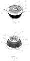
- the Figures 1 and 2 show schematically different views of a spring balancer 1 for a sliding part according to an embodiment of the present invention.
- the spring balancer 1 comprises a rope drum 2 with a tension element or rope 3 that can be unwound.
- the rope drum 2 has a recess that opens into a groove 5 with a comparatively smaller cross section on the circumference of the rope drum 2, so that the rope end 4 has a larger cross section than the groove 5 by means of a thickening that can be inserted into the recess , relative to the cable drum 2 can be fixed.
- the groove 5 runs spirally along the outer circumference of the cable drum 2.
- the cable 3 When the cable 3 is subjected to a tensile load, it unwinds from the cable drum 2, with the cable drum rotating about an axis of rotation 7 against the spring force of a spiral spring 6 located inside the cable drum 2.
- the cable drum 2 has a diameter that decreases from one axial end to the opposite axial end.
- the rope drum 2 has a diameter that decreases from one end of the groove 5 at the rope end 4 to the other end of the groove 5 .
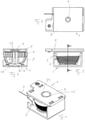
- the cable drum 2 is arranged in a housing 8 .
- the housing 8 is arranged and fastened to a non-sliding guide 10 for a sliding part 9 .
- the end of the rope 3 opposite the rope end 4 is detachably anchored to a rope holder 11 .
- the cable holder 11 is formed by two matching hook pieces 12 which are arranged next to one another and parallel to one another and are at a predetermined distance from one another.
- a T-piece 13 is arranged as a projection for hanging, the length of which is greater transversely to the rope 3 than the distance between the two hook pieces 12, so that the T-piece 13 can engage behind the hook pieces 12 and on the T-piece 13 attacking rope 3 between the hook pieces 12 passes through.
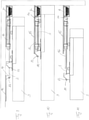
- the figure 10 shows the (closed) state of rest, with the sliding part 9 being moved by the cable 3 and the spring force acting on the cable 3 up to a stop. If the sliding part 9 is formed by a sliding door of a cabinet, then this state corresponds to a closed sliding door. To open the sliding part 9, it is pushed against the spring force acting on the cable 3 (to the left in the drawing orientation), as shown in FIG figure 11 shown.
- a counter-hook 14 is also shown on a displaceable guide carriage 15 .
- the counter-hook 14 is also formed by two parallel hook pieces formed, the distance between these hook pieces deviating from the distance between the hook pieces 12 .
- the counter-hook 14 on the guide carriage 15 therefore has the function of a driver, with the help of which the traction cable can be detached from the cable holder 11 or unhooked from it. In this state, a simple assembly or disassembly of the sliding part 9 is possible.
- a damper 16 is arranged between the cable holder 11 and the housing 8, which serves as a stop for the sliding part 9 and dampens the sliding movement at least shortly before the stop.
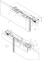
- FIG 12 shows an embodiment of the present invention in which the sliding part is formed by a central door 17 sliding in two opposite directions.
- first and second spring balancers 18 and 19, acting in opposite directions, are provided on the guide 10 with first and second cables 20, 21, the ends of which are fastened by means of first and second T-pieces 22, 23 to the first and second cable holders 26, 27 are anchorable.
- the cable holders 26 and 27 are attached to the upper narrow side of the middle door 17 .
- first and second fixed counter hooks 24, 25 serve to couple and detach the T-pieces 22, 23 to and from the cable holders 26, 27.
- the coil spring 6 of the spring balancer 1 has a predetermined prestress, the coil spring 6 being held in the prestressed state relative to the housing 8 .
- a locking disk 28 non-rotatably connected to the axis of rotation 7 with a plurality of projections 29, the projections 29 engaging in corresponding recesses in an opposite, complementarily shaped inner side 30 of an outer wall 31 of the housing 8.
- the axis of rotation 7 is rotated, with the projections of the locking disk 28 being pushed over the projections formed between the recesses on the inside 30 of the outer wall 31 in order to engage in the recesses that are adjacent in the direction of rotation, with the outer wall 31 moving relative to the Axis of rotation deformed axially outwards.
- the Projections 29 have first and second flanks 32, 33 along their radial longitudinal extent on both sides, the first flanks 32 being steeper than the second flanks 33, as a result of which the projections 29 have the shape of an asymmetrical trapezium in cross section.
- the flatter flanks 33 point in the direction that corresponds to the direction of rotation for tensioning the coil spring 6
- the steeper flanks 32 point in the opposite direction, which corresponds to the direction of rotation for relaxing the coil spring 6 .
- the design of the flanks 32, 33 thus takes into account the supporting or inhibiting force of the spiral spring 6 acting in the direction of rotation.
- the rotation of the axis of rotation 7 for tensioning or slackening of the spiral spring 6 can take place by means of a hexagonal wrench which can be inserted into a corresponding bore 34 in the axis of rotation 7 .
Landscapes
- Closing And Opening Devices For Wings, And Checks For Wings (AREA)
Claims (13)
- Dispositif comprenantune pièce coulissante (17),au moins un guide (10) orienté dans sa direction de coulissement etau moins un équilibreur à ressort (18, 19) contre la force duquel la pièce coulissante (17) peut coulisser sur au moins une partie de sa course de coulissement, de sorte qu'au moins une partie du coulissement opposé est soutenue ou exécutable par force de ressort,dans lequel l'au moins un équilibreur à ressort (18, 19) comprend au moins un ressort (6), ainsi qu'un tambour de câble (2) monté de façon pivotante le contenant avec un élément de traction ou câble (3) pouvant être déroulé contre la force du ressort (6),et dans lequel un boîtier (8) de l'au moins un équilibreur à ressort (18, 19) est disposé dans la région du guide (10) et l'extrémité de l'élément de traction ou du câble (20, 21) peut être couplée avec la pièce coulissante (17),caractérisé en ce quela pièce coulissante (9) est une porte coulissante ou centrale (17) pouvant coulisser de deux côtés opposés,deux équilibreurs à ressort (18, 19) espacés et agissant en sens contraires sont disposés chacun avec des crochets opposés fixes (24, 25) dans la région du guide (10) etla porte coulissante ou centrale (17) présente quant à elle deux saillies en forme de crochet (26, 27) qui sont formées de deux pièces en crochet, les crochets opposés fixes (24, 25) des équilibreurs à ressort (18, 19) étant prévus sur un chemin de coulissement des saillies en forme de crochet (26, 27) de la porte coulissante ou centrale (17), de sorte que la porte coulissante ou centrale (17) peut être accouplée au choix avec le câble (20) d'un équilibreur à ressort (18) ou avec le câble (21) de l'autre équilibreur à ressort (19) lors de son coulissement dans l'une ou dans l'autre direction, et chaque crochet opposé (24, 25) présentant deux pièces en crochet parallèles situées à une distance de la porte coulissante ou centrale différente des saillies en forme de crochet.
- Dispositif selon la revendication 1, caractérisé en outre en ce que le tambour de câble (2) présente sur sa face extérieure au moins un renfoncement ou une gorge (5) disposé en forme d'hélice pour recevoir le câble (3) et/ou que le tambour de câble (2) de l'au moins un équilibreur à ressort (1) présente un diamètre croissant de l'extrémité de la bobine de câble jusqu'au côté de la partie de câble la dernière à se dérouler lors de l'extraction du câble (3), de sorte que, lors du coulissement de la pièce coulissante (9), le diamètre efficace du tambour de câble (2) est d'abord le plus petit, puis grandit au fur et à mesure de l'extraction du câble (3), et que, lors du retrait du câble (3) par la force du ressort (6) tendu de l'équilibreur à ressort (1), le câble (3) peut s'enrouler d'abord sur le plus grand diamètre du tambour de câble (2), puis, au fur et à mesure du retrait par la force de ressort, sur un diamètre toujours plus petit du tambour de câble (2), l'axe de rotation du tambour de câble (2) étant disposé perpendiculairement à la direction de déplacement et en particulier dans le plan du mouvement de coulissement et/ou perpendiculairement à l'orientation du guide de la pièce coulissante (9) et/ou de son petit côté.
- Dispositif selon la revendication 1 ou 2, caractérisé en outre en ce que la longueur d'extraction du câble (3) de l'au moins un équilibreur à ressort (1) relié à la pièce coulissante (9) correspond à plus de la moitié de la plus grande course de coulissement possible ou de la longueur totale de la course de coulissement de la pièce coulissante (9).
- Dispositif selon une des revendications 1 à 3, caractérisé en outre en ce que le mouvement du câble (3) à l'extérieur du boîtier (8) de l'équilibreur à ressort (1) est rectiligne dans la direction de coulissement de la pièce coulissante.
- Dispositif selon une des revendications 1 à 4, caractérisé en outre en ce que, pour la position de fermeture de la pièce coulissante (9) avec l'équilibreur à ressort (1) disposé pour effectuer un mouvement de fermeture par la force du ressort, il est prévu un tampon ou amortisseur (16) en guise de butée pour la pièce coulissante ou il est prévu que le mouvement de coulissement lors de la fermeture soit amorti et/ou qu'une fermeture ralentie ou en douceur soit effectuée.
- Dispositif selon une des revendications 1 à 5, caractérisé en outre en ce que, pour la position de la pièce coulissante (9) dans laquelle le ressort (6) de l'au moins un équilibreur à ressort (1) est tendu, il est prévu une fixation s'opposant à la force de rappel du ressort (6), par exemple une encoche, un aimant, une pince et/ou un fermoir en particulier actionnable à la main.
- Dispositif selon une des revendications 1 à 6, caractérisé en outre en ce que l'ouverture de crochet de chacune des saillies en forme de crochet pointe dans la direction de coulissement dans laquelle le câble (20, 21) peut être extrait, en s'opposant à la force du ressort (6) du palan, du boîtier de celui-ci, et qu'il est prévu sur le câble (20, 21) ou à l'extrémité du câble une saillie ou un crochet ou un anneau ou une boucle pour l'accrochage dans la saillie en forme de crochet, la saillie en forme de crochet étant formée en particulier de deux pièces de crochet (12) disposées l'une à côté de l'autre et/ou parallèlement entre elles, espacées, en particulier superposées et faisant saillie à l'extrémité du câble de traction (3) pour accrocher une pièce en forme de T (13) dont la longueur transversale par rapport au câble est supérieure à l'écartement des deux pièces de crochet (12), de sorte que le câble (3) accroché à la pièces en forme de T (13) passe entre les pièces de crochet (12) à distance de celles-ci.
- Dispositif selon une des revendications 1 à 7, caractérisé en ce que, sous l'ouverture de crochet, il est prévu une pente pour le guidage de la pièce en forme de T (13) ou de la pièce de couplage de câble (3) dans l'ouverture de crochet, ou pour la compensation en hauteur, en particulier pour compenser les différents écartements entre le guide (10) et la face supérieure de la pièce coulissante (9).
- Dispositif selon une des revendications 1 à 8, caractérisé en ce que, lors du coulissement de la pièce coulissante (9) et de chacune de ses saillies en forme de cochets par rapport aux crochets homologues (24, 25), la pièce de couplage ou la pièce en forme de T (13) sur le câble (3) de l'équilibreur à ressort (1) reste suspendue au crochet homologue (14).
- Dispositif selon une des revendications 1 à 9, caractérisé en ce que les deux saillies en forme de crochets tenant chacune une extrémité d'un des câbles (20, 21) et la ou les saillies en forme de crochets sur la pièce coulissante (9) sont espacées les une par rapport aux autres de telle sorte que, lors du coulissement, la pièce coulissante (9) peut être entraînée dans une direction et l'autre câble (20, 21) peut être fixé dans une position initiale et réciproquement.
- Dispositif selon une des revendications précédentes, caractérisé en ce que les deux câbles (20, 21) sont fixés sur la pièce coulissante (9) ou la porte centrale (17) et qu'après l'ouverture de la pièce coulissante (9) ou de la porte centrale (17) vers un côté, un câble (20), et après l'ouverture dans le sens contraire, l'autre câble (21) est extrait en s'opposant à la force de ressort de l'équilibreur à ressort (18, 19) correspondant et, dans la position centrale, les deux câbles (20, 21) sortent à équidistance de leurs tambours de câble, en particulier sous l'action du ressort d'enroulement correspondant.
- Dispositif selon une des revendications précédentes, caractérisé en ce que le ressort (6) est constitué par un ressort hélicoïdal dont la tension initiale à l'état de repos est réglable en faisant pivoter un axe de rotation (7) relié au ressort hélicoïdal, l'axe de rotation (7) pouvant être encliqueté dans un sens de rotation et l'encliquetage pouvant être débloqué par la rotation de l'axe de rotation (7), l'encliquetage étant conçu de sorte que, pour débloquer l'encliquetage dans le sens de rotation qui correspond à une détente du ressort de rotation, il faut une plus grande force ou un plus grand couple de rotation que dans le sens contraire qui correspond à une tension du ressort hélicoïdal.
- Dispositif selon la revendication 12, caractérisé en ce qu'il est prévu un dispositif d'encliquetage (28) avec au moins une saillie (29) qui, lors de la rotation de l'axe de rotation (7) pour tendre ou détendre le ressort hélicoïdal, doit être surmontée par une pièce homologue, les flancs de la saillie (29) opposés dans le sens de rotation de l'axe de rotation (7) étant de raideurs différentes, en particulier le flanc (32) qui fait face au sens de rotation dans lequel l'axe de rotation (7) peut tourner pour détendre le ressort hélicoïdal étant plus raide que le flanc (33) qui fait face au sens de rotation opposé.
Applications Claiming Priority (1)
| Application Number | Priority Date | Filing Date | Title |
|---|---|---|---|
| DE102014103074.5A DE102014103074B4 (de) | 2014-03-07 | 2014-03-07 | Schiebeteil mit Federzug |
Publications (2)
| Publication Number | Publication Date |
|---|---|
| EP2915942A1 EP2915942A1 (fr) | 2015-09-09 |
| EP2915942B1 true EP2915942B1 (fr) | 2022-03-09 |
Family
ID=51900747
Family Applications (1)
| Application Number | Title | Priority Date | Filing Date |
|---|---|---|---|
| EP14192886.1A Active EP2915942B1 (fr) | 2014-03-07 | 2014-11-12 | Partie coulissante doté de ressort |
Country Status (2)
| Country | Link |
|---|---|
| EP (1) | EP2915942B1 (fr) |
| DE (1) | DE102014103074B4 (fr) |
Families Citing this family (5)
| Publication number | Priority date | Publication date | Assignee | Title |
|---|---|---|---|---|
| DE102015106912A1 (de) * | 2015-05-04 | 2016-11-10 | Carl Stahl Kromer Gmbh | Federzug mit einer Druckfeder |
| JP7094518B2 (ja) * | 2018-04-16 | 2022-07-04 | 株式会社明工 | 引戸の自動閉止装置 |
| JP7743292B2 (ja) * | 2021-12-10 | 2025-09-24 | 文化シヤッター株式会社 | 引戸装置 |
| AT526130A1 (de) * | 2022-04-29 | 2023-11-15 | Blum Gmbh Julius | Anordnung zur Führung wenigstens eines bewegbaren Möbelteiles relativ zu einem Möbelkorpus |
| DE102024136127B3 (de) | 2024-12-04 | 2025-12-31 | Gerd Lämmermann | Schließeinrichtung für eine Schiebetür, insbesondere eine Insektenschutztür |
Family Cites Families (7)
| Publication number | Priority date | Publication date | Assignee | Title |
|---|---|---|---|---|
| US3020580A (en) * | 1959-10-21 | 1962-02-13 | John C Acker | Door closer |
| US3246363A (en) * | 1963-12-19 | 1966-04-19 | John A Rogas | Sliding door closure |
| JPS5524289Y2 (fr) * | 1974-11-06 | 1980-06-10 | ||
| CA2199546A1 (fr) * | 1997-03-10 | 1998-09-10 | Paul Regnier | Dispositif de fermeture pour porte coulissante |
| DE102010023444B4 (de) * | 2010-06-11 | 2014-11-27 | Gerd Lämmermann | Vorsatztür, insbesondere Insektenschutztür |
| DE102011000295A1 (de) * | 2011-01-24 | 2012-03-22 | Trittec Ag | Vorrichtung zum automatischen Schließen oder Öffnen einer Schiebetür |
| DE202012104360U1 (de) * | 2012-11-13 | 2012-11-21 | Häfele GmbH & Co. KG | Bidirektionale Einzugsvorrichtung für eine mittlere Schiebetür |
-
2014
- 2014-03-07 DE DE102014103074.5A patent/DE102014103074B4/de not_active Expired - Fee Related
- 2014-11-12 EP EP14192886.1A patent/EP2915942B1/fr active Active
Also Published As
| Publication number | Publication date |
|---|---|
| EP2915942A1 (fr) | 2015-09-09 |
| DE102014103074B4 (de) | 2016-06-30 |
| DE102014103074A1 (de) | 2015-09-10 |
Similar Documents
| Publication | Publication Date | Title |
|---|---|---|
| EP2915942B1 (fr) | Partie coulissante doté de ressort | |
| EP2851497B1 (fr) | Dispositif de montage réglable pour un élément coulissant et dispositif coulissant | |
| EP2649261B1 (fr) | Dispositif de fermeture et d'amortissement pour éléments de meuble mobiles | |
| EP3220776B1 (fr) | Dispositif d'insertion d'éléments de meuble | |
| DE202009016230U1 (de) | Haltevorrichtung für Raffrollo-Perlenraffseile | |
| DE202012008650U1 (de) | Sonnenschutzaufbau | |
| EP2395195B1 (fr) | Porte additionelle, notamment porte moustiquaire, avec un mécanisme de fermeture automatique | |
| EP3376899B1 (fr) | Dispositif d'escamotage pour éléments de meuble mobiles | |
| CH627310A5 (fr) | ||
| DE102010007128B4 (de) | Dämpfungseinrichtung für schienengeführte Türelemente sowie Verwendung einer derartigen Dämpfungseinrichtung | |
| EP2630320B1 (fr) | Armature de tiroir pour relier un tiroir à une serrure centrale | |
| DE102015106912A1 (de) | Federzug mit einer Druckfeder | |
| EP2202376B1 (fr) | Système de porte coulissante et basculante | |
| DE202008012990U1 (de) | Vorrichtung zum Dämpfen einer Öffnungs- und Schließbewegung von Rollläden, insbesondere für Möbel | |
| DE102010010719B4 (de) | Fensterbetätigungsvorrichtung | |
| DE102010055681B4 (de) | Vorrichtung zum Haltern eines Gegenstands mit Gewichtsausgleich | |
| EP1302620A2 (fr) | Rouleau à ressort | |
| DE102011000295A1 (de) | Vorrichtung zum automatischen Schließen oder Öffnen einer Schiebetür | |
| DE69822414T2 (de) | Fangvorrichtung für rollbare Verschlussvorrichtungen | |
| DE102010064471B3 (de) | Dämpfungseinrichtung für schienengeführte Türelemente | |
| EP1795694B1 (fr) | Moyens d'enroulement régulier des cordes d'un rideau plissé | |
| EP4446546A1 (fr) | Dispositif de fermeture pour un ensemble comprenant un élément coulissant et ensemble | |
| DE102006043971A1 (de) | Flaschenzug mit einem Bremsmittel | |
| EP2317164A1 (fr) | Crochet, notamment pour dispositifs de sécurité | |
| EP3385120B1 (fr) | Dispositif de protection d'une charge |
Legal Events
| Date | Code | Title | Description |
|---|---|---|---|
| PUAI | Public reference made under article 153(3) epc to a published international application that has entered the european phase |
Free format text: ORIGINAL CODE: 0009012 |
|
| AK | Designated contracting states |
Kind code of ref document: A1 Designated state(s): AL AT BE BG CH CY CZ DE DK EE ES FI FR GB GR HR HU IE IS IT LI LT LU LV MC MK MT NL NO PL PT RO RS SE SI SK SM TR |
|
| AX | Request for extension of the european patent |
Extension state: BA ME |
|
| 17P | Request for examination filed |
Effective date: 20160309 |
|
| RBV | Designated contracting states (corrected) |
Designated state(s): AL AT BE BG CH CY CZ DE DK EE ES FI FR GB GR HR HU IE IS IT LI LT LU LV MC MK MT NL NO PL PT RO RS SE SI SK SM TR |
|
| STAA | Information on the status of an ep patent application or granted ep patent |
Free format text: STATUS: EXAMINATION IS IN PROGRESS |
|
| 17Q | First examination report despatched |
Effective date: 20181128 |
|
| GRAP | Despatch of communication of intention to grant a patent |
Free format text: ORIGINAL CODE: EPIDOSNIGR1 |
|
| STAA | Information on the status of an ep patent application or granted ep patent |
Free format text: STATUS: GRANT OF PATENT IS INTENDED |
|
| INTG | Intention to grant announced |
Effective date: 20210915 |
|
| GRAS | Grant fee paid |
Free format text: ORIGINAL CODE: EPIDOSNIGR3 |
|
| GRAA | (expected) grant |
Free format text: ORIGINAL CODE: 0009210 |
|
| STAA | Information on the status of an ep patent application or granted ep patent |
Free format text: STATUS: THE PATENT HAS BEEN GRANTED |
|
| RBV | Designated contracting states (corrected) |
Designated state(s): AL AT BE BG CH CY CZ DK EE ES FI FR GB GR HR HU IE IS IT LI LT LU LV MC MK MT NL NO PL PT RO RS SE SI SK SM TR |
|
| REG | Reference to a national code |
Ref country code: DE Ref legal event code: R108 |
|
| AK | Designated contracting states |
Kind code of ref document: B1 Designated state(s): AL AT BE BG CH CY CZ DK EE ES FI FR GB GR HR HU IE IS IT LI LT LU LV MC MK MT NL NO PL PT RO RS SE SI SK SM TR |
|
| REG | Reference to a national code |
Ref country code: GB Ref legal event code: FG4D Free format text: NOT ENGLISH |
|
| REG | Reference to a national code |
Ref country code: CH Ref legal event code: EP Ref country code: AT Ref legal event code: REF Ref document number: 1474293 Country of ref document: AT Kind code of ref document: T Effective date: 20220315 |
|
| REG | Reference to a national code |
Ref country code: IE Ref legal event code: FG4D Free format text: LANGUAGE OF EP DOCUMENT: GERMAN |
|
| REG | Reference to a national code |
Ref country code: LT Ref legal event code: MG9D |
|
| REG | Reference to a national code |
Ref country code: NL Ref legal event code: MP Effective date: 20220309 |
|
| PG25 | Lapsed in a contracting state [announced via postgrant information from national office to epo] |
Ref country code: SE Free format text: LAPSE BECAUSE OF FAILURE TO SUBMIT A TRANSLATION OF THE DESCRIPTION OR TO PAY THE FEE WITHIN THE PRESCRIBED TIME-LIMIT Effective date: 20220309 Ref country code: RS Free format text: LAPSE BECAUSE OF FAILURE TO SUBMIT A TRANSLATION OF THE DESCRIPTION OR TO PAY THE FEE WITHIN THE PRESCRIBED TIME-LIMIT Effective date: 20220309 Ref country code: NO Free format text: LAPSE BECAUSE OF FAILURE TO SUBMIT A TRANSLATION OF THE DESCRIPTION OR TO PAY THE FEE WITHIN THE PRESCRIBED TIME-LIMIT Effective date: 20220609 Ref country code: LT Free format text: LAPSE BECAUSE OF FAILURE TO SUBMIT A TRANSLATION OF THE DESCRIPTION OR TO PAY THE FEE WITHIN THE PRESCRIBED TIME-LIMIT Effective date: 20220309 Ref country code: HR Free format text: LAPSE BECAUSE OF FAILURE TO SUBMIT A TRANSLATION OF THE DESCRIPTION OR TO PAY THE FEE WITHIN THE PRESCRIBED TIME-LIMIT Effective date: 20220309 Ref country code: BG Free format text: LAPSE BECAUSE OF FAILURE TO SUBMIT A TRANSLATION OF THE DESCRIPTION OR TO PAY THE FEE WITHIN THE PRESCRIBED TIME-LIMIT Effective date: 20220609 |
|
| PG25 | Lapsed in a contracting state [announced via postgrant information from national office to epo] |
Ref country code: LV Free format text: LAPSE BECAUSE OF FAILURE TO SUBMIT A TRANSLATION OF THE DESCRIPTION OR TO PAY THE FEE WITHIN THE PRESCRIBED TIME-LIMIT Effective date: 20220309 Ref country code: GR Free format text: LAPSE BECAUSE OF FAILURE TO SUBMIT A TRANSLATION OF THE DESCRIPTION OR TO PAY THE FEE WITHIN THE PRESCRIBED TIME-LIMIT Effective date: 20220610 Ref country code: FI Free format text: LAPSE BECAUSE OF FAILURE TO SUBMIT A TRANSLATION OF THE DESCRIPTION OR TO PAY THE FEE WITHIN THE PRESCRIBED TIME-LIMIT Effective date: 20220309 |
|
| PG25 | Lapsed in a contracting state [announced via postgrant information from national office to epo] |
Ref country code: NL Free format text: LAPSE BECAUSE OF FAILURE TO SUBMIT A TRANSLATION OF THE DESCRIPTION OR TO PAY THE FEE WITHIN THE PRESCRIBED TIME-LIMIT Effective date: 20220309 |
|
| PG25 | Lapsed in a contracting state [announced via postgrant information from national office to epo] |
Ref country code: SM Free format text: LAPSE BECAUSE OF FAILURE TO SUBMIT A TRANSLATION OF THE DESCRIPTION OR TO PAY THE FEE WITHIN THE PRESCRIBED TIME-LIMIT Effective date: 20220309 Ref country code: SK Free format text: LAPSE BECAUSE OF FAILURE TO SUBMIT A TRANSLATION OF THE DESCRIPTION OR TO PAY THE FEE WITHIN THE PRESCRIBED TIME-LIMIT Effective date: 20220309 Ref country code: RO Free format text: LAPSE BECAUSE OF FAILURE TO SUBMIT A TRANSLATION OF THE DESCRIPTION OR TO PAY THE FEE WITHIN THE PRESCRIBED TIME-LIMIT Effective date: 20220309 Ref country code: PT Free format text: LAPSE BECAUSE OF FAILURE TO SUBMIT A TRANSLATION OF THE DESCRIPTION OR TO PAY THE FEE WITHIN THE PRESCRIBED TIME-LIMIT Effective date: 20220711 Ref country code: ES Free format text: LAPSE BECAUSE OF FAILURE TO SUBMIT A TRANSLATION OF THE DESCRIPTION OR TO PAY THE FEE WITHIN THE PRESCRIBED TIME-LIMIT Effective date: 20220309 Ref country code: EE Free format text: LAPSE BECAUSE OF FAILURE TO SUBMIT A TRANSLATION OF THE DESCRIPTION OR TO PAY THE FEE WITHIN THE PRESCRIBED TIME-LIMIT Effective date: 20220309 Ref country code: CZ Free format text: LAPSE BECAUSE OF FAILURE TO SUBMIT A TRANSLATION OF THE DESCRIPTION OR TO PAY THE FEE WITHIN THE PRESCRIBED TIME-LIMIT Effective date: 20220309 |
|
| PG25 | Lapsed in a contracting state [announced via postgrant information from national office to epo] |
Ref country code: PL Free format text: LAPSE BECAUSE OF FAILURE TO SUBMIT A TRANSLATION OF THE DESCRIPTION OR TO PAY THE FEE WITHIN THE PRESCRIBED TIME-LIMIT Effective date: 20220309 Ref country code: IS Free format text: LAPSE BECAUSE OF FAILURE TO SUBMIT A TRANSLATION OF THE DESCRIPTION OR TO PAY THE FEE WITHIN THE PRESCRIBED TIME-LIMIT Effective date: 20220709 Ref country code: AL Free format text: LAPSE BECAUSE OF FAILURE TO SUBMIT A TRANSLATION OF THE DESCRIPTION OR TO PAY THE FEE WITHIN THE PRESCRIBED TIME-LIMIT Effective date: 20220309 |
|
| PLBE | No opposition filed within time limit |
Free format text: ORIGINAL CODE: 0009261 |
|
| STAA | Information on the status of an ep patent application or granted ep patent |
Free format text: STATUS: NO OPPOSITION FILED WITHIN TIME LIMIT |
|
| PG25 | Lapsed in a contracting state [announced via postgrant information from national office to epo] |
Ref country code: DK Free format text: LAPSE BECAUSE OF FAILURE TO SUBMIT A TRANSLATION OF THE DESCRIPTION OR TO PAY THE FEE WITHIN THE PRESCRIBED TIME-LIMIT Effective date: 20220309 |
|
| 26N | No opposition filed |
Effective date: 20221212 |
|
| PG25 | Lapsed in a contracting state [announced via postgrant information from national office to epo] |
Ref country code: SI Free format text: LAPSE BECAUSE OF FAILURE TO SUBMIT A TRANSLATION OF THE DESCRIPTION OR TO PAY THE FEE WITHIN THE PRESCRIBED TIME-LIMIT Effective date: 20220309 |
|
| PG25 | Lapsed in a contracting state [announced via postgrant information from national office to epo] |
Ref country code: MC Free format text: LAPSE BECAUSE OF FAILURE TO SUBMIT A TRANSLATION OF THE DESCRIPTION OR TO PAY THE FEE WITHIN THE PRESCRIBED TIME-LIMIT Effective date: 20220309 |
|
| GBPC | Gb: european patent ceased through non-payment of renewal fee |
Effective date: 20221112 |
|
| REG | Reference to a national code |
Ref country code: BE Ref legal event code: MM Effective date: 20221130 |
|
| PG25 | Lapsed in a contracting state [announced via postgrant information from national office to epo] |
Ref country code: LU Free format text: LAPSE BECAUSE OF NON-PAYMENT OF DUE FEES Effective date: 20221112 |
|
| PG25 | Lapsed in a contracting state [announced via postgrant information from national office to epo] |
Ref country code: IE Free format text: LAPSE BECAUSE OF NON-PAYMENT OF DUE FEES Effective date: 20221112 Ref country code: GB Free format text: LAPSE BECAUSE OF NON-PAYMENT OF DUE FEES Effective date: 20221112 |
|
| PG25 | Lapsed in a contracting state [announced via postgrant information from national office to epo] |
Ref country code: BE Free format text: LAPSE BECAUSE OF NON-PAYMENT OF DUE FEES Effective date: 20221130 |
|
| PGFP | Annual fee paid to national office [announced via postgrant information from national office to epo] |
Ref country code: IT Payment date: 20231130 Year of fee payment: 10 Ref country code: FR Payment date: 20231124 Year of fee payment: 10 Ref country code: CH Payment date: 20231201 Year of fee payment: 10 Ref country code: AT Payment date: 20231117 Year of fee payment: 10 |
|
| PG25 | Lapsed in a contracting state [announced via postgrant information from national office to epo] |
Ref country code: HU Free format text: LAPSE BECAUSE OF FAILURE TO SUBMIT A TRANSLATION OF THE DESCRIPTION OR TO PAY THE FEE WITHIN THE PRESCRIBED TIME-LIMIT; INVALID AB INITIO Effective date: 20141112 |
|
| PG25 | Lapsed in a contracting state [announced via postgrant information from national office to epo] |
Ref country code: CY Free format text: LAPSE BECAUSE OF FAILURE TO SUBMIT A TRANSLATION OF THE DESCRIPTION OR TO PAY THE FEE WITHIN THE PRESCRIBED TIME-LIMIT Effective date: 20220309 |
|
| PG25 | Lapsed in a contracting state [announced via postgrant information from national office to epo] |
Ref country code: MK Free format text: LAPSE BECAUSE OF FAILURE TO SUBMIT A TRANSLATION OF THE DESCRIPTION OR TO PAY THE FEE WITHIN THE PRESCRIBED TIME-LIMIT Effective date: 20220309 |
|
| REG | Reference to a national code |
Ref country code: AT Ref legal event code: HC Ref document number: 1474293 Country of ref document: AT Kind code of ref document: T Owner name: KROMER GMBH, DE Effective date: 20240809 |
|
| PG25 | Lapsed in a contracting state [announced via postgrant information from national office to epo] |
Ref country code: MT Free format text: LAPSE BECAUSE OF FAILURE TO SUBMIT A TRANSLATION OF THE DESCRIPTION OR TO PAY THE FEE WITHIN THE PRESCRIBED TIME-LIMIT Effective date: 20220309 |
|
| REG | Reference to a national code |
Ref country code: CH Ref legal event code: PL |
|
| REG | Reference to a national code |
Ref country code: AT Ref legal event code: MM01 Ref document number: 1474293 Country of ref document: AT Kind code of ref document: T Effective date: 20241112 Ref country code: CH Ref legal event code: PL |
|
| PG25 | Lapsed in a contracting state [announced via postgrant information from national office to epo] |
Ref country code: CH Free format text: LAPSE BECAUSE OF NON-PAYMENT OF DUE FEES Effective date: 20241130 |
|
| PG25 | Lapsed in a contracting state [announced via postgrant information from national office to epo] |
Ref country code: AT Free format text: LAPSE BECAUSE OF NON-PAYMENT OF DUE FEES Effective date: 20241112 |
|
| PG25 | Lapsed in a contracting state [announced via postgrant information from national office to epo] |
Ref country code: IT Free format text: LAPSE BECAUSE OF NON-PAYMENT OF DUE FEES Effective date: 20241112 |
|
| PG25 | Lapsed in a contracting state [announced via postgrant information from national office to epo] |
Ref country code: FR Free format text: LAPSE BECAUSE OF NON-PAYMENT OF DUE FEES Effective date: 20241130 |
|
| PG25 | Lapsed in a contracting state [announced via postgrant information from national office to epo] |
Ref country code: TR Free format text: LAPSE BECAUSE OF FAILURE TO SUBMIT A TRANSLATION OF THE DESCRIPTION OR TO PAY THE FEE WITHIN THE PRESCRIBED TIME-LIMIT Effective date: 20220309 |