EP2354411A1 - Fenêtres d'énergie dont le verre est une pièce de support - Google Patents
Fenêtres d'énergie dont le verre est une pièce de support Download PDFInfo
- Publication number
- EP2354411A1 EP2354411A1 EP10008274A EP10008274A EP2354411A1 EP 2354411 A1 EP2354411 A1 EP 2354411A1 EP 10008274 A EP10008274 A EP 10008274A EP 10008274 A EP10008274 A EP 10008274A EP 2354411 A1 EP2354411 A1 EP 2354411A1
- Authority
- EP
- European Patent Office
- Prior art keywords
- sash
- frame
- glass
- window
- frame part
- Prior art date
- Legal status (The legal status is an assumption and is not a legal conclusion. Google has not performed a legal analysis and makes no representation as to the accuracy of the status listed.)
- Withdrawn
Links
Images


Classifications
-
- E—FIXED CONSTRUCTIONS
- E06—DOORS, WINDOWS, SHUTTERS, OR ROLLER BLINDS IN GENERAL; LADDERS
- E06B—FIXED OR MOVABLE CLOSURES FOR OPENINGS IN BUILDINGS, VEHICLES, FENCES OR LIKE ENCLOSURES IN GENERAL, e.g. DOORS, WINDOWS, BLINDS, GATES
- E06B3/00—Window sashes, door leaves, or like elements for closing wall or like openings; Layout of fixed or moving closures, e.g. windows in wall or like openings; Features of rigidly-mounted outer frames relating to the mounting of wing frames
- E06B3/54—Fixing of glass panes or like plates
- E06B3/5454—Fixing of glass panes or like plates inside U-shaped section members
-
- E—FIXED CONSTRUCTIONS
- E06—DOORS, WINDOWS, SHUTTERS, OR ROLLER BLINDS IN GENERAL; LADDERS
- E06B—FIXED OR MOVABLE CLOSURES FOR OPENINGS IN BUILDINGS, VEHICLES, FENCES OR LIKE ENCLOSURES IN GENERAL, e.g. DOORS, WINDOWS, BLINDS, GATES
- E06B1/00—Border constructions of openings in walls, floors, or ceilings; Frames to be rigidly mounted in such openings
- E06B1/70—Sills; Thresholds
- E06B1/702—Window sills
-
- E—FIXED CONSTRUCTIONS
- E06—DOORS, WINDOWS, SHUTTERS, OR ROLLER BLINDS IN GENERAL; LADDERS
- E06B—FIXED OR MOVABLE CLOSURES FOR OPENINGS IN BUILDINGS, VEHICLES, FENCES OR LIKE ENCLOSURES IN GENERAL, e.g. DOORS, WINDOWS, BLINDS, GATES
- E06B3/00—Window sashes, door leaves, or like elements for closing wall or like openings; Layout of fixed or moving closures, e.g. windows in wall or like openings; Features of rigidly-mounted outer frames relating to the mounting of wing frames
- E06B3/54—Fixing of glass panes or like plates
- E06B3/56—Fixing of glass panes or like plates by means of putty, cement, or adhesives only
Definitions
- the invention concerns an energy window comprising a sash part with glass and a frame part.
- the invention further concerns, respectively, a sash part with glass and a frame part to be used as part of an energy window.
- EP 1,353,035B1 , DE 100 36 265 and FR 2 881 784 describe a window or door having a sash and a frame.
- both the sash and the frame parts are quite thick and complex resulting in that quite a large area of the window opening is filled by the sash and frame leaving less space for the glass part.
- the object of the invention is to solve the above-mentioned problems.
- an energy window for mounting in a building wherein said window comprises a frame part and a sash part with a glass part, said frame part being adapted for connecting to said building, said sash part and said frame part being interconnected by hinges making it possible to open and close said energy window by opening and closing said sash part relative to said frame part.
- the frame part is a substantially flat plate wherein said sash part also comprises a flat plate and two flanges resulting in a U shape with an opening between said two flanges for receiving said glass part and wherein said sash part further comprises a third flange pointing in the opposite direction compared to said two flanges overlapping the front of the frame part.
- This configuration reduces the area taken up by the sash and frame part and results in the glass part of the window taking up a larger part of the total area of the entire window (sash + glass).
- the effective area of glass in the window frame is increased. This increases the effective amount of sunlight entering into the building through windows.
- the third flange pointing in the opposite direction compared to said two flanges overlapping the front of the frame part ensures that the frame part can be at least partly and even completely hidden behind the third flange and it is possible to position a gasket between the third flange and the front of the frame part. Having gaskets positioned both in the front between the third flange and the frame and in the back of the window creates a cavity between the two gaskets resulting in a very low heat loss between frame and sash and removes thermal bridges.
- said sash part is glued to said glass part, resulting in a sash part where the glass part is the bearing part.
- said sash part comprises four side pieces, each side piece having been separately connected to the glass part. This is a very simple method of mounting the sash to the glass part.
- said sash part and said frame part are made from fiber composite. This is a very light material with quite strong properties. Further, by using composite material the sash and frame are less sensitive to moisture or dryness as a result of the humidity of the air.
- Figure 1 a and 1b illustrate the principle behind the sash part of an energy window according to the present invention, in an unassembled state and in an assembled state, respectively.
- FIG 1 a the glass part 101 of a window and the profile of the sash part 103 are illustrated.
- the sash profile comprises a U shape with two flanges 105, 107 ensuring that the sash part 103 can be positioned around the edges of the glass part 101.
- the glass part 101 is thereby positioned between the flanges 105, 107, and the distance between the flanges 105, 107 corresponds to the thickness of the glass part 101 in such a way that the flanges can be mounted around the glass part.
- the sash part 103 has been connected to the glass part by mounting the sash part 103 on the glass part, and further glue 109 has been used to secure the sash part to the glass part 101.
- the glue is positioned between the flanges 105, 107 and the edge of the glass part.
- the glue 109 could be positioned differently; the important thing is that a sufficiently strong connection between the glass part 101 and the sash part 103 is obtained.
- the glue 109 could e.g. be fast drying hot melt glue or any other glue being useable for creating a strong connection between the material of the sash part 103 and the glass part 101.
- the sash part further comprises a third flange 108 pointing in the opposite direction compared to the two flanges 105, 107 overlapping at least part of said frame part. This third flange can be used for covering at least part of the frame part of the energy window (described later) and also for generating a first isolating barrier between the sash part and the frame part to avoid a thermal bridge.
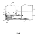
- the parts of the energy window according to an embodiment of the present invention are illustrated as a cut seen from the side.
- the side 200 is outside and the side 202 is inside.
- the basic elements of the energy windows according to the present invention are the sash part 203 with a glass part 201 and the frame part 213.
- the frame part 213 is a substantially flat plate which can be mounted to a surface of a window opening
- the sash part 203 comprises a flat plate 208 with two flanges 205, 207 resulting in a U-shape with an opening between the flanges wherein the glass part 201 is positioned.
- this embodiment of the sash part comprises a third flange 202 pointing in the opposite direction compared to the two flanges 205, 207 and overlapping the front 214 of the frame part 213.
- the third flange could be dimensioned differently relative to the frame and thereby only partly overlapping the frame.
- the window comprises the glass part 201 and the sash part 203 with flanges 205, 207 mounted around the edge of the glass part 201.
- the sash part 203 has been designed having a composite sash part 204 - and on the inside a wooden sash part 209.
- the window is mounted to a frame part 211 via hinges 210, where hinge elements are mounted on the sash part 203 of the window and the frame part 211, respectively, enabling opening of the window.
- the frame part 211 has been designed having a composite frame part 213 and a wooden frame part 215. In the embodiment in figure 2 the window has been mounted to the composite frame part 213 of the frame part 211.
- gaskets 217 are mounted between the frame and the third flange 202 of the sash part enabling a sealing barrier, whereby the frame and the sash are closely sealed, which further helps reducing the heat migrating from the inside to the outside of the window in the building.
- a cavity is generated between the two gaskets resulting in a very low heat loss between frame and sash.
- a fourth flange is positioned behind the third flange, whereby a small gap is generated wherein a gasket can be mounted. This gap results in a better grip on the gasket, whereby the position of the gap is maintained.
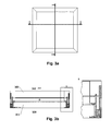
- Figure 3a, 3b and 3c illustrate an embodiment of an energy window described in figure 2 , seen from different angles.
- the window is seen from the front.
- Figure 3b shows the window along the axis A-A where 301 is the glass part and 303 is part of the frame.
- the side 300 is outside and the side 302 is inside.
- the encircled area D is enlarged and identical to figure 2 .
- Figure 3c shows the window along the axis B-B where 301 is the glass part and 303 is part of the frame.
- the side 300 is outside and the side 302 is inside and 304 is the top and 306 is the bottom of the window.
- Figure 4a and 4b illustrate the window in an opened position seen from different angles.
- the sash part 301 with the glass part in one embodiment opens up in a way where the sash is hinged 305 to the sides of the frame 303, and where the bottom of the sash part opens up away from the frame.
- Figure 4b is seen from the same angle as figure 3c , but with the window opened instead of closed. Again, here the side 300 is outside and the side 302 is inside and 304 is the top and 306 is the bottom of the window.
- the sash is hinged to the bottom or the top of the frame so that the sash part can open up in any way the user wants it to.
- the sash is fixed to the frame rendering it impossible to open the window.
Landscapes
- Engineering & Computer Science (AREA)
- Civil Engineering (AREA)
- Structural Engineering (AREA)
- Wing Frames And Configurations (AREA)
Priority Applications (1)
| Application Number | Priority Date | Filing Date | Title |
|---|---|---|---|
| EP10008274A EP2354411A1 (fr) | 2010-01-04 | 2010-08-09 | Fenêtres d'énergie dont le verre est une pièce de support |
Applications Claiming Priority (2)
| Application Number | Priority Date | Filing Date | Title |
|---|---|---|---|
| EP10000001A EP2354416A1 (fr) | 2010-01-04 | 2010-01-04 | Fenêtres d'énergie dont le verre est une pièce de support |
| EP10008274A EP2354411A1 (fr) | 2010-01-04 | 2010-08-09 | Fenêtres d'énergie dont le verre est une pièce de support |
Publications (1)
| Publication Number | Publication Date |
|---|---|
| EP2354411A1 true EP2354411A1 (fr) | 2011-08-10 |
Family
ID=41719146
Family Applications (2)
| Application Number | Title | Priority Date | Filing Date |
|---|---|---|---|
| EP10000001A Withdrawn EP2354416A1 (fr) | 2010-01-04 | 2010-01-04 | Fenêtres d'énergie dont le verre est une pièce de support |
| EP10008274A Withdrawn EP2354411A1 (fr) | 2010-01-04 | 2010-08-09 | Fenêtres d'énergie dont le verre est une pièce de support |
Family Applications Before (1)
| Application Number | Title | Priority Date | Filing Date |
|---|---|---|---|
| EP10000001A Withdrawn EP2354416A1 (fr) | 2010-01-04 | 2010-01-04 | Fenêtres d'énergie dont le verre est une pièce de support |
Country Status (1)
| Country | Link |
|---|---|
| EP (2) | EP2354416A1 (fr) |
Families Citing this family (1)
| Publication number | Priority date | Publication date | Assignee | Title |
|---|---|---|---|---|
| CN103628774A (zh) * | 2013-12-12 | 2014-03-12 | 谷新运 | 一种太阳能升降窗台 |
Citations (6)
| Publication number | Priority date | Publication date | Assignee | Title |
|---|---|---|---|---|
| GB701393A (en) * | 1951-02-26 | 1953-12-23 | Albert Victor Cotton | Improvements in or relating to metal window casements |
| NL8002106A (nl) * | 1980-04-10 | 1981-11-02 | Herpen Frederik Cornelis Van | Profiel voor een paneel, in het bijzonder glaspaneel. |
| EP0982463A2 (fr) * | 1998-08-27 | 2000-03-01 | Uwe Trabert | Appui de fenêtre |
| DE10036265A1 (de) | 2000-07-26 | 2002-03-07 | Rehau Ag & Co | Fenster- oder Türflügel |
| EP1353035A2 (fr) * | 2002-03-20 | 2003-10-15 | REHAU AG + Co | Fenêtre ou porte |
| FR2881784A1 (fr) | 2005-02-07 | 2006-08-11 | Imtec Sarl | Construction des vantaux ouvrants de menuiseries par collage du cadre sur la peripherie du remplissage porteur |
Family Cites Families (1)
| Publication number | Priority date | Publication date | Assignee | Title |
|---|---|---|---|---|
| US20050081981A1 (en) * | 2003-10-16 | 2005-04-21 | Heikkila Kurt E. | Groove glazed window sash and fabrication method |
-
2010
- 2010-01-04 EP EP10000001A patent/EP2354416A1/fr not_active Withdrawn
- 2010-08-09 EP EP10008274A patent/EP2354411A1/fr not_active Withdrawn
Patent Citations (7)
| Publication number | Priority date | Publication date | Assignee | Title |
|---|---|---|---|---|
| GB701393A (en) * | 1951-02-26 | 1953-12-23 | Albert Victor Cotton | Improvements in or relating to metal window casements |
| NL8002106A (nl) * | 1980-04-10 | 1981-11-02 | Herpen Frederik Cornelis Van | Profiel voor een paneel, in het bijzonder glaspaneel. |
| EP0982463A2 (fr) * | 1998-08-27 | 2000-03-01 | Uwe Trabert | Appui de fenêtre |
| DE10036265A1 (de) | 2000-07-26 | 2002-03-07 | Rehau Ag & Co | Fenster- oder Türflügel |
| EP1353035A2 (fr) * | 2002-03-20 | 2003-10-15 | REHAU AG + Co | Fenêtre ou porte |
| EP1353035B1 (fr) | 2002-03-20 | 2007-04-25 | REHAU AG + Co | Fenêtre ou porte |
| FR2881784A1 (fr) | 2005-02-07 | 2006-08-11 | Imtec Sarl | Construction des vantaux ouvrants de menuiseries par collage du cadre sur la peripherie du remplissage porteur |
Also Published As
| Publication number | Publication date |
|---|---|
| EP2354416A1 (fr) | 2011-08-10 |
Similar Documents
| Publication | Publication Date | Title |
|---|---|---|
| ITBZ20110056A1 (it) | Telai per serramenti in materiale termoplastico saldabile, rivestibili con materiali diversi | |
| EP3002402A1 (fr) | Agencement de battant ouvrable de fenêtre ou porte sans cadre à vitrage isolant | |
| CA2931125C (fr) | Porte multipanneau sans joint | |
| US12366108B2 (en) | Insulating glass element and sauna cabin comprising the insulating glass element | |
| US20080196331A1 (en) | Window frame with lip for covering windows | |
| CA1071475A (fr) | Fenetres a fermeture-eclair pour maisons | |
| EP2450642B1 (fr) | Volet de désenfumage à portillon | |
| JP6182349B2 (ja) | 防火建具 | |
| KR20160004112A (ko) | 커튼월과 스윙도어의 연결구조 | |
| EP1844207B1 (fr) | Dispositif et procede de fixation de fenetres sur une structure de paroi externe | |
| JP2004003337A (ja) | 折り畳み装置 | |
| EP2354416A1 (fr) | Fenêtres d'énergie dont le verre est une pièce de support | |
| WO2007042038A3 (fr) | Element de fenetre, panneau profile pultrude, systeme de panneau profile pultrude et un ou plusieurs elements de fixation, protection de batiment ou maison, batiment ou maison, procede de fabrication d'une protection externe resistant aux intemperies et element de batiment | |
| KR101565961B1 (ko) | 창호용 미들 프레임 및 이를 구비한 창호 프레임 | |
| CN102400631A (zh) | 一种玻璃肋点式玻璃幕墙的电动开启窗 | |
| KR101583536B1 (ko) | 커튼월과 미서기 문의 연결구조 | |
| CN208347578U (zh) | 一种错位折叠窗 | |
| US20200173224A1 (en) | Cover assembly for windows | |
| JP2008297784A (ja) | 断熱ドア | |
| GB2565796A (en) | Cladding assembly | |
| JP5650931B2 (ja) | 連段窓、及びその製造方法 | |
| CN102337826B (zh) | 单轨推拉门玻璃压线固定玻璃扇结构 | |
| CN208267674U (zh) | 一种钢制异形门 | |
| EP3737819A1 (fr) | Structure en verre ouvrable comprenant des profils de protection | |
| CN212054447U (zh) | 一种多功能防水摆式速通门 |
Legal Events
| Date | Code | Title | Description |
|---|---|---|---|
| PUAI | Public reference made under article 153(3) epc to a published international application that has entered the european phase |
Free format text: ORIGINAL CODE: 0009012 |
|
| AK | Designated contracting states |
Kind code of ref document: A1 Designated state(s): AL AT BE BG CH CY CZ DE DK EE ES FI FR GB GR HR HU IE IS IT LI LT LU LV MC MK MT NL NO PL PT RO SE SI SK SM TR |
|
| AX | Request for extension of the european patent |
Extension state: BA ME RS |
|
| STAA | Information on the status of an ep patent application or granted ep patent |
Free format text: STATUS: THE APPLICATION IS DEEMED TO BE WITHDRAWN |
|
| 18D | Application deemed to be withdrawn |
Effective date: 20120211 |