EP2354687B1 - Ouverture de plafond pour installations climatiques - Google Patents
Ouverture de plafond pour installations climatiques Download PDFInfo
- Publication number
- EP2354687B1 EP2354687B1 EP10152568A EP10152568A EP2354687B1 EP 2354687 B1 EP2354687 B1 EP 2354687B1 EP 10152568 A EP10152568 A EP 10152568A EP 10152568 A EP10152568 A EP 10152568A EP 2354687 B1 EP2354687 B1 EP 2354687B1
- Authority
- EP
- European Patent Office
- Prior art keywords
- air outlet
- change material
- room
- phase
- outlet according
- Prior art date
- Legal status (The legal status is an assumption and is not a legal conclusion. Google has not performed a legal analysis and makes no representation as to the accuracy of the status listed.)
- Active
Links
Images


Classifications
-
- F—MECHANICAL ENGINEERING; LIGHTING; HEATING; WEAPONS; BLASTING
- F24—HEATING; RANGES; VENTILATING
- F24F—AIR-CONDITIONING; AIR-HUMIDIFICATION; VENTILATION; USE OF AIR CURRENTS FOR SCREENING
- F24F13/00—Details common to, or for air-conditioning, air-humidification, ventilation or use of air currents for screening
- F24F13/08—Air-flow control members, e.g. louvres, grilles, flaps or guide plates
- F24F13/10—Air-flow control members, e.g. louvres, grilles, flaps or guide plates movable, e.g. dampers
-
- F—MECHANICAL ENGINEERING; LIGHTING; HEATING; WEAPONS; BLASTING
- F24—HEATING; RANGES; VENTILATING
- F24F—AIR-CONDITIONING; AIR-HUMIDIFICATION; VENTILATION; USE OF AIR CURRENTS FOR SCREENING
- F24F1/00—Room units for air-conditioning, e.g. separate or self-contained units or units receiving primary air from a central station
- F24F1/01—Room units for air-conditioning, e.g. separate or self-contained units or units receiving primary air from a central station in which secondary air is induced by injector action of the primary air
-
- F—MECHANICAL ENGINEERING; LIGHTING; HEATING; WEAPONS; BLASTING
- F24—HEATING; RANGES; VENTILATING
- F24F—AIR-CONDITIONING; AIR-HUMIDIFICATION; VENTILATION; USE OF AIR CURRENTS FOR SCREENING
- F24F13/00—Details common to, or for air-conditioning, air-humidification, ventilation or use of air currents for screening
- F24F13/02—Ducting arrangements
- F24F13/06—Outlets for directing or distributing air into rooms or spaces, e.g. ceiling air diffuser
-
- F—MECHANICAL ENGINEERING; LIGHTING; HEATING; WEAPONS; BLASTING
- F24—HEATING; RANGES; VENTILATING
- F24F—AIR-CONDITIONING; AIR-HUMIDIFICATION; VENTILATION; USE OF AIR CURRENTS FOR SCREENING
- F24F5/00—Air-conditioning systems or apparatus not covered by F24F1/00 or F24F3/00, e.g. using solar heat or combined with household units such as an oven or water heater
- F24F5/0007—Air-conditioning systems or apparatus not covered by F24F1/00 or F24F3/00, e.g. using solar heat or combined with household units such as an oven or water heater cooling apparatus specially adapted for use in air-conditioning
- F24F5/0017—Air-conditioning systems or apparatus not covered by F24F1/00 or F24F3/00, e.g. using solar heat or combined with household units such as an oven or water heater cooling apparatus specially adapted for use in air-conditioning using cold storage bodies, e.g. ice
-
- F—MECHANICAL ENGINEERING; LIGHTING; HEATING; WEAPONS; BLASTING
- F24—HEATING; RANGES; VENTILATING
- F24F—AIR-CONDITIONING; AIR-HUMIDIFICATION; VENTILATION; USE OF AIR CURRENTS FOR SCREENING
- F24F5/00—Air-conditioning systems or apparatus not covered by F24F1/00 or F24F3/00, e.g. using solar heat or combined with household units such as an oven or water heater
- F24F5/0007—Air-conditioning systems or apparatus not covered by F24F1/00 or F24F3/00, e.g. using solar heat or combined with household units such as an oven or water heater cooling apparatus specially adapted for use in air-conditioning
- F24F5/0017—Air-conditioning systems or apparatus not covered by F24F1/00 or F24F3/00, e.g. using solar heat or combined with household units such as an oven or water heater cooling apparatus specially adapted for use in air-conditioning using cold storage bodies, e.g. ice
- F24F5/0021—Air-conditioning systems or apparatus not covered by F24F1/00 or F24F3/00, e.g. using solar heat or combined with household units such as an oven or water heater cooling apparatus specially adapted for use in air-conditioning using cold storage bodies, e.g. ice using phase change material [PCM] for storage
-
- F—MECHANICAL ENGINEERING; LIGHTING; HEATING; WEAPONS; BLASTING
- F24—HEATING; RANGES; VENTILATING
- F24F—AIR-CONDITIONING; AIR-HUMIDIFICATION; VENTILATION; USE OF AIR CURRENTS FOR SCREENING
- F24F13/00—Details common to, or for air-conditioning, air-humidification, ventilation or use of air currents for screening
- F24F13/08—Air-flow control members, e.g. louvres, grilles, flaps or guide plates
-
- F—MECHANICAL ENGINEERING; LIGHTING; HEATING; WEAPONS; BLASTING
- F24—HEATING; RANGES; VENTILATING
- F24F—AIR-CONDITIONING; AIR-HUMIDIFICATION; VENTILATION; USE OF AIR CURRENTS FOR SCREENING
- F24F13/00—Details common to, or for air-conditioning, air-humidification, ventilation or use of air currents for screening
- F24F13/02—Ducting arrangements
- F24F13/06—Outlets for directing or distributing air into rooms or spaces, e.g. ceiling air diffuser
- F24F2013/0616—Outlets that have intake openings
-
- F—MECHANICAL ENGINEERING; LIGHTING; HEATING; WEAPONS; BLASTING
- F24—HEATING; RANGES; VENTILATING
- F24F—AIR-CONDITIONING; AIR-HUMIDIFICATION; VENTILATION; USE OF AIR CURRENTS FOR SCREENING
- F24F2221/00—Details or features not otherwise provided for
- F24F2221/14—Details or features not otherwise provided for mounted on the ceiling
-
- Y—GENERAL TAGGING OF NEW TECHNOLOGICAL DEVELOPMENTS; GENERAL TAGGING OF CROSS-SECTIONAL TECHNOLOGIES SPANNING OVER SEVERAL SECTIONS OF THE IPC; TECHNICAL SUBJECTS COVERED BY FORMER USPC CROSS-REFERENCE ART COLLECTIONS [XRACs] AND DIGESTS
- Y02—TECHNOLOGIES OR APPLICATIONS FOR MITIGATION OR ADAPTATION AGAINST CLIMATE CHANGE
- Y02E—REDUCTION OF GREENHOUSE GAS [GHG] EMISSIONS, RELATED TO ENERGY GENERATION, TRANSMISSION OR DISTRIBUTION
- Y02E60/00—Enabling technologies; Technologies with a potential or indirect contribution to GHG emissions mitigation
- Y02E60/14—Thermal energy storage
Definitions
- the invention relates to a Deckenluftauslass for air conditioning systems, with a, in particular elongated, consisting of a housing housing with a Zu povertyeinlass and at least one room-side air outlet, the Zu povertyeinlass in a, preferably located in the housing, and in particular extending along the housing , Distributor space opens, wherein the distributor space has at least one pointing in the direction of the air outlet injection nozzle and wherein the room side next to the (the) air outlet (air outlets) is provided a room air inlet for inducing Jardinlauft.
- Such ceiling air outlets are known in various designs (See, for example, patent document US-A-2002062948 ). They are to distribute the supply air supplied by an air conditioner more or less evenly in the room. In order to be able to blow cooled supply air into the room via such ceiling air outlets, it is necessary to provide an upstream refrigerating machine, as seen in the flow direction of the ceiling air outlet.
- the object of the invention is to avoid the aforementioned drawback and to provide a Decken Kunststoffauslass without the use of a separate chiller allows at least some cooling of the supply air.
- a phase change material is provided in the region of the room air inlet and at least one injection nozzle is associated with a device which is variable between a first setting and a second setting, wherein in the first setting an induction of the drawn through the phase change material room air is given by directing the at least predominant portion of the supply air to the air outlet and in the second setting, there is a flow of at least the major part of the supply air through the phase change material into the space to be ventilated.
- the ceiling air outlet may have a round or angled as well as square or rectangular configuration. At the same time, at least the predominant part of the supply air can be given to the air outlet or even the complete portion. Likewise, a predominant portion of the supply air can be passed through the phase change material into the space to be ventilated or even the entire portion can be given.
- phase change material also called phase transition material
- phase transition material consists for example of salt hydrates and / or paraffins, which store and release heat during the phase transition.
- the utilization of the phase transition solid-liquid is the most frequently used principle.
- special salts or paraffins are melted as a storage medium, which absorb a lot of heat energy (heat of fusion). Since this process is reversible, the storage medium returns exactly this amount of heat during solidification.
- phase change material is particularly well suited as a storage medium because even in the phase change very high amounts of energy are absorbed or released without the temperature of the phase change material changes significantly.
- phase change material itself can be continuous for the room or supply air and thus flowed through. But it is also possible that the phase change material in a construction, such as a channel system, is present, in which case the structure itself is flowed through.
- a setting is selected in which at least the majority of the supply air or the entire supply air flows through the phase change material into the room to be ventilated. In this case, the phase change material heat is removed.
- the Decken Kunststoffauslass invention is operated in the setting in which at least the majority of the supply air or the entire supply air is directed to the air outlet and thereby induction by the phase change material passed through room air takes place.
- the phase change material is the stored cold to the Kunststofflauft from.
- the room air is cooled, so that the room is not only ventilated by blowing the supply air and the cooled induced room air, but also cooled. This can be dispensed with a separate cooling circuit and so the energy costs are reduced.
- the phase change material can be arranged on the side of the room air inlet facing away from the space to be ventilated.
- the housing can be quadrangular, in particular rectangular, formed in the lateral section. In this case, it is advisable if the housing in the region of the edge facing the room is beveled outwardly, so that the housing widens in the area of the air outlet.
- the upper portion of the Decken Kunststoffauslasses may be formed as a distributor space.
- the distribution space is arranged in the housing.
- the claimed by the phase change material space may be smaller than the width of the housing to form at least one lateral Lucasauslassspaltes between the phase change material and the phase change material adjacent housing wall of the housing.
- an outlet gap not only on one side of the phase change material is provided an outlet gap.
- the phase change material may be airtight or air-permeable. In the latter case, for example, the supply air can also flow via the sides into the phase change material.
- At least one device can be designed as a flap that can be changed in the flow cross-section of the air outlet.
- the flap can be a horizontal be mounted pivotally mounted pivot axis.
- the axis is arranged in the region of the air outlet and the flap is mounted on one side. Then the flap points against the direction of flow.
- the flap can for example be driven by a motor.
- At least two injection nozzles and one device which either opens the flow cross section of the one or the flow cross section of the other injection nozzle can be arranged in the distributor space such that the one injection nozzle for induction of the room air drawn through the phase change material by directing the at least predominant portion of the supply air the air outlet is aligned and the other injection nozzle for flowing at least the majority of the supply air through the phase change material in the space to be ventilated is aligned with the phase change material.
- At least one device can be designed as a slide.
- a heat exchanger In the area of the room air inlet, a heat exchanger can be arranged. Then a temperature, in particular of the induced room air is possible.
- each storage space of at least two storage walls is limited and the opposite storage walls of two adjacent storage spaces form between them a flow channel through which the supply air or the room air flows, wherein the storage walls of the storage spaces have alternately arranged raised areas and recessed areas.
- each storage space may consist of a substantially uniform wall thickness having material and distributed over its surface each alternately arranged raised areas and recessed areas, wherein each memory space of its two storage walls with respect to their respective raised areas and recessed areas are coordinated so that their respective recessed areas are aligned pointing away from each other in the opposite direction and their respective raised areas are aligned facing each other, wherein the respective raised areas of the storage walls are connected to each other directly or via a connecting element, in particular via an adhesive, welding or soldering.
- the raised areas and the recessed areas may have approximately the same contour.
- the cross-section of these regions may taper towards the highest partial regions of the raised regions or to the deepest partial regions of the recessed regions.
- At least one storage wall can be formed as a sheet, preferably as an aluminum sheet. At least one storage wall can be made of plastic.
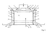
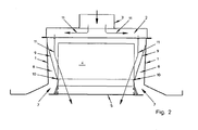
- a Deckenluftauslass which consists of an elongated housing with a housing 1.
- the upper area of the ceiling air outlet is designed as a distributor space 2.
- the distribution chamber 2 opens a Zulufteinlass 3.
- the housing is Seen in the lateral section formed approximately at right angles.
- phase change material 4 is arranged centrally.
- the phase change material 4 is arranged on the side of a room air inlet 5 facing away from the space to be ventilated.
- each housing wall 1 is beveled outwardly, so that the housing expands here.
- the distributor space 2 per air outlet 7 has at least one injection nozzle 8 pointing in the direction of the air outlet 7.
- the ceiling air outlets according to the invention also have facilities 9, which are changeable between a first setting and a second setting.
- each air outlet 7 as a device 9 a flow cross-section of the air outlet 7 changeable flap is provided which is pivotally mounted about a horizontally oriented pivot axis 10.
- the flap is mounted on one side and points opposite to the direction of flow.
- FIGS. 1 and 3 the position of both flaps is shown in day mode.
- the supply air (arrow 11) flows through the distributor chamber 2 and the injection nozzles 8 in the direction of the respective air outlet 7.
- room air (arrow 12) is induced, which is pulled through the phase change material 4 therethrough.
- the stored cold to the Jardinlauft 12 from. As a result, the room air 12 is cooled.
- the cooled room air 12 and the supply air 11 mix and are blown together in the room to be ventilated (arrow 13).
- FIGS. 5 to 8 an alternative embodiment is shown.
- at least two injection nozzles 8 and a corresponding device 9 designed as a slide are provided in the distributor space 2.
- the slide has two recesses 14 whose spacing is identical to the distance between the two associated injection nozzles 8.
- the width of the slider may also be less than the distance between the two associated injection nozzles 8. In this case, there is no need for recesses 14. The slide only has to be displaced so far that it releases one injection nozzle 8 in the respective end position and covers the other injection nozzle 8.
- a heat exchanger 16 is still provided in the region of the room air inlet 5, so that here is also a heating optionally also an additional cooling of the induced air in particular (arrow 12) is possible.
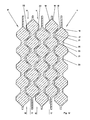
- each storage space 17 is filled with the phase change material 4.
- the size of each storage space 17 may be, for example, about 15.4x31 cm. Of course, for example, a square training is possible.
- the storage spaces 17 may be held, for example, in a frame, not shown.
- Each storage space 17 consists of two storage walls 18, 19. As in particular Fig. 9 can be seen, each storage wall 18, 19 distributed over its surface in each case alternately arranged raised and recessed areas 20, 21. Each storage wall 18, 19 consists of a substantially uniform wall thickness material. The storage walls 18, 19 are circumferentially connected to each other on their entire outer circumference of the storage space 17.
- the raised portions 20 and the recessed portions 21 correspond to each other with the reverse orientation.
- the two opposite storage walls 18, 19 of a storage space 17 are arranged relative to one another such that the raised areas 20 of the storage wall 19 pointing in the direction of the storage wall 18 are arranged approximately opposite the raised areas 20 of the storage wall 18 pointing in the direction of the storage wall 18.
- the recessed areas 21 of both storage walls 18, 19 of a storage space 17 are aligned pointing away from each other.
- the raised portions 20 and the recessed portions 21 are formed in a truncated cone shape, wherein the raised portions 20 and the recessed portions 21 are slightly flattened on the upper side.
- Each storage space 17 is filled with the phase change material 4.
- the opposing raised portions 20 of the storage walls 18, 19 do not touch, so that the phase change material 4 is also provided in this area.
- the storage walls 18, 19 are also connected to each other in the remaining, previously open portion 24.
- Adjacent storage spaces 17 are arranged so that the recessed areas 21 of the one storage space 17 and the recessed areas 21 of the other adjacent storage space 17 offset from each other and in a view orthogonal to the general extent of the storage space 17 small distance. In the illustrated arrangement, the recessed area 21 of the one storage space 17 projects into the raised area 20 of the other adjacent storage space 17.
- two adjacent storage spaces 17 may be fixed by means of spacers 23 against each other.
- a heat-conducting element such as metal wool, may be provided.
Landscapes
- Engineering & Computer Science (AREA)
- Chemical & Material Sciences (AREA)
- Combustion & Propulsion (AREA)
- Mechanical Engineering (AREA)
- General Engineering & Computer Science (AREA)
- Life Sciences & Earth Sciences (AREA)
- Sustainable Development (AREA)
- Duct Arrangements (AREA)
Claims (16)
- Sortie d'air de plafond pour des systèmes de climatisation, avec un boîtier réalisé notamment oblong, constitué d'une paroi de boîtier (1) et doté d'une entrée d'air d'alimentation (3) et d'au moins une sortie d'air (7) côté local, sachant que l'entrée d'air d'alimentation (3) débouche dans une chambre de distribution (2) se trouvant de préférence dans le boîtier et s'étendant notamment le long du boîtier, sachant que la chambre de distribution (2) présente au moins une buse d'injection (8) dirigée vers la sortie d'air (7) et sachant qu'une entrée d'air ambiant (5) est prévue côté local à côté de la ou des sortie(s) d'air (7) pour l'induction d'air ambiant (12), caractérisée en ce qu'un matériau à changement de phase (4) est prévu dans la région de l'entrée d'air ambiant (5) et au moins un organe (9) qui peut être modifié entre un premier réglage et un deuxième réglage est associé à la buse d'injection (8), sachant que dans le premier réglage, on obtient une induction de l'air ambiant (12) aspiré à travers le matériau à changement de phase (4) en dirigeant au moins une part prépondérante de l'air d'alimentation (11) vers la sortie d'air (7), et que dans le deuxième réglage, on obtient un écoulement d'au moins une part prépondérante de l'air d'alimentation (11) à travers le matériau à changement de phase (4), en direction du local à ventiler.
- Sortie d'air de plafond selon la revendication précédente, caractérisée en ce que le matériau à changement de phase (4) est disposé sur le côté de l'entrée d'air ambiant (5) qui est opposé au local à ventiler.
- Sortie d'air de plafond selon l'une des revendications précédentes, caractérisée en ce que le boîtier est réalisé quadrangulaire, en particulier rectangulaire, considéré en coupe latérale.
- Sortie d'air de plafond selon l'une des revendications précédentes, caractérisée en ce que la région supérieure de la sortie d'air de plafond est conçue comme chambre de distribution (2).
- Sortie d'air de plafond selon l'une des revendications précédentes, caractérisée en ce que l'espace occupé par le matériau à changement de phase (4) est prévu plus petit que la largeur du boîtier, en formant au moins un passage latéral de sortie d'air (6) entre le matériau à changement de phase (4) et la paroi (1) du boîtier qui est voisine du matériau à changement de phase (4).
- Sortie d'air de plafond selon l'une des revendications précédentes, caractérisée en ce qu'au moins un organe (9) est réalisé sous forme de volet pouvant modifier la section d'écoulement de la sortie d'air (7).
- Sortie d'air de plafond selon l'une des revendications précédentes, caractérisée en ce qu'au moins deux buses d'injection (8), et un organe (9) libérant soit la section d'écoulement de la première buse d'injection (8) soit la section d'écoulement de l'autre buse d'injection (8), sont disposés dans la chambre de distribution (2) pour chaque sortie d'air (7) de telle sorte que la première buse d'injection (8) est orientée pour l'induction de l'air ambiant (12) aspiré à travers le matériau à changement de phase (4) en dirigeant au moins une part prépondérante de l'air d'alimentation (11) vers la sortie d'air (7), et que l'autre buse d'injection (8) est orientée vers le matériau à changement de phase (4), pour l'écoulement d'au moins une part prépondérante de l'air d'alimentation (11) à travers le matériau à changement de phase (4), en direction du local à ventiler.
- Sortie d'air de plafond selon la revendication précédente, caractérisée en ce qu'au moins un organe (9) est réalisé sous forme de tiroir.
- Sortie d'air de plafond selon l'une des revendications 7 ou 8, caractérisée en ce qu'il est prévu un organe commun (9) pour plusieurs buses d'injection (8), en particulier pour toutes les buses d'injection (8).
- Sortie d'air de plafond selon l'une des revendications précédentes, caractérisée en ce qu'un échangeur de chaleur (16) est disposé dans la région de l'entrée d'air ambiant (5).
- Sortie d'air de plafond selon l'une des revendications précédentes, caractérisée en ce qu'il est prévu au moins deux chambres d'accumulation (17), disposées de préférence dans un boîtier, orientées dans leur orientation générale respective sensiblement parallèlement entre elles et remplies du matériau à changement de phase (4), sachant que chaque chambre d'accumulation (17) est délimitée par au moins deux parois d'accumulateur (18, 19) et que les parois d'accumulateur opposées (18, 19) de deux chambres d'accumulation voisines (17) forment entre elles un canal d'écoulement (22) par lequel s'écoule l'air d'alimentation (11) ou l'air ambiant (12), sachant que les parois d'accumulateur (18, 19) des chambres d'accumulation (17) présentent des régions en relief (20) et des régions en creux (21) alternativement disposées.
- Sortie d'air de plafond selon la revendication précédente, caractérisée en ce que les parois d'accumulateur opposées (18, 19) de chambres d'accumulation voisines (17), parois qui correspondent à l'étendue générale de la chambre d'accumulation (17), sont en ce qui concerne leurs régions en relief (20) et leurs régions en creux (21) mutuellement adaptées de telle sorte que, considéré dans la direction d'écoulement (flèches 11 ou 12), on obtient dans la région des parois d'accumulateur opposées (18, 19) un canal d'écoulement (22) ayant une hauteur de canal sensiblement approximativement uniforme sur toute la longueur du canal et sur toute la largeur du canal.
- Sortie d'air de plafond selon l'une des deux revendications précédentes, caractérisée en ce que les régions en relief (20) et les régions en creux (21) ont approximativement le même contour.
- Sortie d'air de plafond selon l'une des revendications précédentes, caractérisée en ce que la section de ces régions (20, 21) se rétrécit en direction des régions partielles les plus hautes des régions en relief (20), respectivement des régions partielles les plus basses des régions en creux (21).
- Sortie d'air de plafond selon l'une des revendications 11 à 14, caractérisée en ce qu'au moins une paroi d'accumulateur (18, 19) est réalisée sous forme de tôle, de préférence de tôle d'aluminium.
- Sortie d'air de plafond selon l'une des revendications 11 à 15, caractérisée en ce qu'au moins une paroi d'accumulateur (18, 19) est en matière plastique.
Priority Applications (2)
| Application Number | Priority Date | Filing Date | Title |
|---|---|---|---|
| EP10152568A EP2354687B1 (fr) | 2010-02-03 | 2010-02-03 | Ouverture de plafond pour installations climatiques |
| ES10152568T ES2393853T3 (es) | 2010-02-03 | 2010-02-03 | Salida de aire de techo para instalaciones de aire acondicionado |
Applications Claiming Priority (1)
| Application Number | Priority Date | Filing Date | Title |
|---|---|---|---|
| EP10152568A EP2354687B1 (fr) | 2010-02-03 | 2010-02-03 | Ouverture de plafond pour installations climatiques |
Publications (2)
| Publication Number | Publication Date |
|---|---|
| EP2354687A1 EP2354687A1 (fr) | 2011-08-10 |
| EP2354687B1 true EP2354687B1 (fr) | 2012-09-26 |
Family
ID=42244613
Family Applications (1)
| Application Number | Title | Priority Date | Filing Date |
|---|---|---|---|
| EP10152568A Active EP2354687B1 (fr) | 2010-02-03 | 2010-02-03 | Ouverture de plafond pour installations climatiques |
Country Status (2)
| Country | Link |
|---|---|
| EP (1) | EP2354687B1 (fr) |
| ES (1) | ES2393853T3 (fr) |
Families Citing this family (8)
| Publication number | Priority date | Publication date | Assignee | Title |
|---|---|---|---|---|
| DE202012101635U1 (de) * | 2012-04-05 | 2012-06-22 | Trox Gmbh | Einrichtung zum Belüften, zum Heizen und/oder zum Kühlen eines Raumes |
| DE102013200587A1 (de) * | 2013-01-16 | 2014-07-17 | Caverion Deutschland GmbH | Luftauslass zur Konditionierung von Raumluft eines Raumes sowie zugehöriges Verfahren |
| FR3022616B1 (fr) * | 2014-06-24 | 2019-05-03 | Electricite De France | Equipement et procede de distribution d'energie thermique par flux d'air avec stockage de chaleur latente |
| NL2016194B1 (nl) * | 2015-10-05 | 2017-05-02 | Global-E-Systems Europa B V | Modulaire warmtewisselaar. |
| CN107366978B (zh) * | 2017-08-31 | 2023-07-28 | 广东美的制冷设备有限公司 | 天花机 |
| PL4229348T3 (pl) * | 2020-10-19 | 2026-02-16 | Stoschek, Jan | Moduł magazynujący, płyta magazynująca ciepło i urządzenie magazynujące ciepło |
| IT202100010184A1 (it) * | 2021-04-21 | 2022-10-21 | Ste Srl | Impianti di climatizzazione per ambienti |
| DE102021120799B4 (de) * | 2021-08-10 | 2025-05-28 | Framatome Gmbh | Belüftungs- und Klimatisierungssystem und Gebäude |
Family Cites Families (4)
| Publication number | Priority date | Publication date | Assignee | Title |
|---|---|---|---|---|
| NO154444L (fr) * | 1981-11-28 | |||
| FI117682B (fi) * | 2000-11-24 | 2007-01-15 | Halton Oy | Tuloilmalaite |
| KR20050006350A (ko) * | 2003-07-08 | 2005-01-17 | 엘지전자 주식회사 | 공기 청정기 |
| DE102006030830A1 (de) * | 2006-06-30 | 2008-01-03 | Martin Hess | Klimagerät, insbesondere zum Kühlen eines Innenraums |
-
2010
- 2010-02-03 EP EP10152568A patent/EP2354687B1/fr active Active
- 2010-02-03 ES ES10152568T patent/ES2393853T3/es active Active
Also Published As
| Publication number | Publication date |
|---|---|
| EP2354687A1 (fr) | 2011-08-10 |
| ES2393853T3 (es) | 2012-12-28 |
Similar Documents
| Publication | Publication Date | Title |
|---|---|---|
| EP2354687B1 (fr) | Ouverture de plafond pour installations climatiques | |
| DE69432612T2 (de) | Verdampfungswärmetauscher mit geschlossenem direktem und indirektem Kreislauf in Kombination | |
| DE102009020531B3 (de) | Wärmespeicher mit mindestens einem Speicherelement | |
| EP1559980B1 (fr) | Echangeur de chaleur à plaques | |
| EP0757206B1 (fr) | Grille pour un foyer | |
| DE1551489A1 (de) | Waermeaustauscher | |
| WO2015140040A1 (fr) | Module de chauffage et de refroidissement | |
| EP2565321B1 (fr) | Séchoir doté d'un échangeur thermique à flux croisé et son procédé de fonctionnement | |
| DE3909175A1 (de) | Verfahren und vorrichtung zur behandlung von monofilen | |
| DE112017001907T5 (de) | Energiewiedergewinnungseinheit für den Fahrzeuggebrauch | |
| EP4232758B1 (fr) | Dispositif d'aération | |
| DE2328186C2 (de) | Induktionsgerät | |
| DE102011051526B4 (de) | Klimatisierungseinrichtung zum Konditionieren eines Luftstroms | |
| DE10240795A1 (de) | Wärmeübertrageranordnung und Heiz-/Kühlkreislauf für eine Klimaanlage eines Fahrzeugs und Verfahren zur Steuerung und/oder Regelung eines Heiz-/Kühlkreislaufes einer Klimaanlage | |
| DE4313567C1 (de) | Wärmetauscher für die unabhängige Beheizung der Fahrer- und Beifahrerseite eines Fahrgastraumes von Personenkraftwagen | |
| EP1488175B1 (fr) | Systeme de renouvellement d'air comprenant un echangeur thermique, concu pour aerer une piece d'un batiment | |
| DE3725797C1 (fr) | ||
| EP1050618A1 (fr) | Echangeur de chaleur pour sèche-linge | |
| EP0125673B1 (fr) | Echangeur de chaleur | |
| DE19934886C1 (de) | Deckenkonvektor | |
| DE102016113137A1 (de) | Gas-Fluid-Gegenstromwärmetauscher | |
| WO2018210596A1 (fr) | Dispositif échangeur de chaleur et procédé d'échange de chaleur entre l'air et un fluide guidé dans un échangeur de chaleur | |
| DE202017007333U1 (de) | Wärmeaustauschereinrichtung | |
| DE648440C (de) | Rippenrohrwaermeaustauscher | |
| EP1382916A2 (fr) | Echangeur de chaleur avec tapis de tubes capillaires en plastic enroulés en spirale et méthode d'utilisation |
Legal Events
| Date | Code | Title | Description |
|---|---|---|---|
| PUAI | Public reference made under article 153(3) epc to a published international application that has entered the european phase |
Free format text: ORIGINAL CODE: 0009012 |
|
| AK | Designated contracting states |
Kind code of ref document: A1 Designated state(s): AT BE BG CH CY CZ DE DK EE ES FI FR GB GR HR HU IE IS IT LI LT LU LV MC MK MT NL NO PL PT RO SE SI SK SM TR |
|
| AX | Request for extension of the european patent |
Extension state: AL BA RS |
|
| 17P | Request for examination filed |
Effective date: 20110929 |
|
| GRAP | Despatch of communication of intention to grant a patent |
Free format text: ORIGINAL CODE: EPIDOSNIGR1 |
|
| RIC1 | Information provided on ipc code assigned before grant |
Ipc: F24F 5/00 20060101ALI20120425BHEP Ipc: F24F 1/01 20110101AFI20120425BHEP Ipc: F24F 13/06 20060101ALI20120425BHEP Ipc: F24F 13/10 20060101ALI20120425BHEP |
|
| GRAS | Grant fee paid |
Free format text: ORIGINAL CODE: EPIDOSNIGR3 |
|
| GRAA | (expected) grant |
Free format text: ORIGINAL CODE: 0009210 |
|
| AK | Designated contracting states |
Kind code of ref document: B1 Designated state(s): AT BE BG CH CY CZ DE DK EE ES FI FR GB GR HR HU IE IS IT LI LT LU LV MC MK MT NL NO PL PT RO SE SI SK SM TR |
|
| REG | Reference to a national code |
Ref country code: GB Ref legal event code: FG4D Free format text: NOT ENGLISH |
|
| REG | Reference to a national code |
Ref country code: CH Ref legal event code: EP |
|
| REG | Reference to a national code |
Ref country code: AT Ref legal event code: REF Ref document number: 577243 Country of ref document: AT Kind code of ref document: T Effective date: 20121015 |
|
| REG | Reference to a national code |
Ref country code: IE Ref legal event code: FG4D Free format text: LANGUAGE OF EP DOCUMENT: GERMAN |
|
| REG | Reference to a national code |
Ref country code: DE Ref legal event code: R096 Ref document number: 502010001331 Country of ref document: DE Effective date: 20121129 |
|
| REG | Reference to a national code |
Ref country code: NL Ref legal event code: T3 |
|
| REG | Reference to a national code |
Ref country code: ES Ref legal event code: FG2A Ref document number: 2393853 Country of ref document: ES Kind code of ref document: T3 Effective date: 20121228 |
|
| PG25 | Lapsed in a contracting state [announced via postgrant information from national office to epo] |
Ref country code: LT Free format text: LAPSE BECAUSE OF FAILURE TO SUBMIT A TRANSLATION OF THE DESCRIPTION OR TO PAY THE FEE WITHIN THE PRESCRIBED TIME-LIMIT Effective date: 20120926 Ref country code: HR Free format text: LAPSE BECAUSE OF FAILURE TO SUBMIT A TRANSLATION OF THE DESCRIPTION OR TO PAY THE FEE WITHIN THE PRESCRIBED TIME-LIMIT Effective date: 20120926 Ref country code: NO Free format text: LAPSE BECAUSE OF FAILURE TO SUBMIT A TRANSLATION OF THE DESCRIPTION OR TO PAY THE FEE WITHIN THE PRESCRIBED TIME-LIMIT Effective date: 20121226 Ref country code: FI Free format text: LAPSE BECAUSE OF FAILURE TO SUBMIT A TRANSLATION OF THE DESCRIPTION OR TO PAY THE FEE WITHIN THE PRESCRIBED TIME-LIMIT Effective date: 20120926 |
|
| REG | Reference to a national code |
Ref country code: LT Ref legal event code: MG4D Effective date: 20120926 |
|
| PG25 | Lapsed in a contracting state [announced via postgrant information from national office to epo] |
Ref country code: GR Free format text: LAPSE BECAUSE OF FAILURE TO SUBMIT A TRANSLATION OF THE DESCRIPTION OR TO PAY THE FEE WITHIN THE PRESCRIBED TIME-LIMIT Effective date: 20121227 Ref country code: LV Free format text: LAPSE BECAUSE OF FAILURE TO SUBMIT A TRANSLATION OF THE DESCRIPTION OR TO PAY THE FEE WITHIN THE PRESCRIBED TIME-LIMIT Effective date: 20120926 Ref country code: SE Free format text: LAPSE BECAUSE OF FAILURE TO SUBMIT A TRANSLATION OF THE DESCRIPTION OR TO PAY THE FEE WITHIN THE PRESCRIBED TIME-LIMIT Effective date: 20120926 Ref country code: SI Free format text: LAPSE BECAUSE OF FAILURE TO SUBMIT A TRANSLATION OF THE DESCRIPTION OR TO PAY THE FEE WITHIN THE PRESCRIBED TIME-LIMIT Effective date: 20120926 |
|
| PG25 | Lapsed in a contracting state [announced via postgrant information from national office to epo] |
Ref country code: CZ Free format text: LAPSE BECAUSE OF FAILURE TO SUBMIT A TRANSLATION OF THE DESCRIPTION OR TO PAY THE FEE WITHIN THE PRESCRIBED TIME-LIMIT Effective date: 20120926 Ref country code: EE Free format text: LAPSE BECAUSE OF FAILURE TO SUBMIT A TRANSLATION OF THE DESCRIPTION OR TO PAY THE FEE WITHIN THE PRESCRIBED TIME-LIMIT Effective date: 20120926 Ref country code: RO Free format text: LAPSE BECAUSE OF FAILURE TO SUBMIT A TRANSLATION OF THE DESCRIPTION OR TO PAY THE FEE WITHIN THE PRESCRIBED TIME-LIMIT Effective date: 20120926 Ref country code: IS Free format text: LAPSE BECAUSE OF FAILURE TO SUBMIT A TRANSLATION OF THE DESCRIPTION OR TO PAY THE FEE WITHIN THE PRESCRIBED TIME-LIMIT Effective date: 20130126 |
|
| PG25 | Lapsed in a contracting state [announced via postgrant information from national office to epo] |
Ref country code: PL Free format text: LAPSE BECAUSE OF FAILURE TO SUBMIT A TRANSLATION OF THE DESCRIPTION OR TO PAY THE FEE WITHIN THE PRESCRIBED TIME-LIMIT Effective date: 20120926 Ref country code: SK Free format text: LAPSE BECAUSE OF FAILURE TO SUBMIT A TRANSLATION OF THE DESCRIPTION OR TO PAY THE FEE WITHIN THE PRESCRIBED TIME-LIMIT Effective date: 20120926 Ref country code: PT Free format text: LAPSE BECAUSE OF FAILURE TO SUBMIT A TRANSLATION OF THE DESCRIPTION OR TO PAY THE FEE WITHIN THE PRESCRIBED TIME-LIMIT Effective date: 20130128 |
|
| PG25 | Lapsed in a contracting state [announced via postgrant information from national office to epo] |
Ref country code: BG Free format text: LAPSE BECAUSE OF FAILURE TO SUBMIT A TRANSLATION OF THE DESCRIPTION OR TO PAY THE FEE WITHIN THE PRESCRIBED TIME-LIMIT Effective date: 20121226 Ref country code: DK Free format text: LAPSE BECAUSE OF FAILURE TO SUBMIT A TRANSLATION OF THE DESCRIPTION OR TO PAY THE FEE WITHIN THE PRESCRIBED TIME-LIMIT Effective date: 20120926 |
|
| PLBE | No opposition filed within time limit |
Free format text: ORIGINAL CODE: 0009261 |
|
| STAA | Information on the status of an ep patent application or granted ep patent |
Free format text: STATUS: NO OPPOSITION FILED WITHIN TIME LIMIT |
|
| BERE | Be: lapsed |
Owner name: TROX G.M.B.H. Effective date: 20130228 |
|
| 26N | No opposition filed |
Effective date: 20130627 |
|
| PG25 | Lapsed in a contracting state [announced via postgrant information from national office to epo] |
Ref country code: MC Free format text: LAPSE BECAUSE OF NON-PAYMENT OF DUE FEES Effective date: 20130228 |
|
| REG | Reference to a national code |
Ref country code: DE Ref legal event code: R097 Ref document number: 502010001331 Country of ref document: DE Effective date: 20130627 |
|
| PG25 | Lapsed in a contracting state [announced via postgrant information from national office to epo] |
Ref country code: CY Free format text: LAPSE BECAUSE OF FAILURE TO SUBMIT A TRANSLATION OF THE DESCRIPTION OR TO PAY THE FEE WITHIN THE PRESCRIBED TIME-LIMIT Effective date: 20120926 |
|
| REG | Reference to a national code |
Ref country code: IE Ref legal event code: MM4A |
|
| PG25 | Lapsed in a contracting state [announced via postgrant information from national office to epo] |
Ref country code: IE Free format text: LAPSE BECAUSE OF NON-PAYMENT OF DUE FEES Effective date: 20130203 Ref country code: BE Free format text: LAPSE BECAUSE OF NON-PAYMENT OF DUE FEES Effective date: 20130228 |
|
| PG25 | Lapsed in a contracting state [announced via postgrant information from national office to epo] |
Ref country code: MT Free format text: LAPSE BECAUSE OF FAILURE TO SUBMIT A TRANSLATION OF THE DESCRIPTION OR TO PAY THE FEE WITHIN THE PRESCRIBED TIME-LIMIT Effective date: 20120926 |
|
| PGFP | Annual fee paid to national office [announced via postgrant information from national office to epo] |
Ref country code: ES Payment date: 20150223 Year of fee payment: 6 Ref country code: IT Payment date: 20150225 Year of fee payment: 6 |
|
| PG25 | Lapsed in a contracting state [announced via postgrant information from national office to epo] |
Ref country code: SM Free format text: LAPSE BECAUSE OF FAILURE TO SUBMIT A TRANSLATION OF THE DESCRIPTION OR TO PAY THE FEE WITHIN THE PRESCRIBED TIME-LIMIT Effective date: 20120926 |
|
| PG25 | Lapsed in a contracting state [announced via postgrant information from national office to epo] |
Ref country code: TR Free format text: LAPSE BECAUSE OF FAILURE TO SUBMIT A TRANSLATION OF THE DESCRIPTION OR TO PAY THE FEE WITHIN THE PRESCRIBED TIME-LIMIT Effective date: 20120926 |
|
| PG25 | Lapsed in a contracting state [announced via postgrant information from national office to epo] |
Ref country code: LU Free format text: LAPSE BECAUSE OF NON-PAYMENT OF DUE FEES Effective date: 20130203 Ref country code: MK Free format text: LAPSE BECAUSE OF FAILURE TO SUBMIT A TRANSLATION OF THE DESCRIPTION OR TO PAY THE FEE WITHIN THE PRESCRIBED TIME-LIMIT Effective date: 20120926 Ref country code: HU Free format text: LAPSE BECAUSE OF FAILURE TO SUBMIT A TRANSLATION OF THE DESCRIPTION OR TO PAY THE FEE WITHIN THE PRESCRIBED TIME-LIMIT; INVALID AB INITIO Effective date: 20100203 |
|
| REG | Reference to a national code |
Ref country code: FR Ref legal event code: PLFP Year of fee payment: 7 |
|
| PG25 | Lapsed in a contracting state [announced via postgrant information from national office to epo] |
Ref country code: IT Free format text: LAPSE BECAUSE OF NON-PAYMENT OF DUE FEES Effective date: 20160203 |
|
| REG | Reference to a national code |
Ref country code: FR Ref legal event code: PLFP Year of fee payment: 8 |
|
| PG25 | Lapsed in a contracting state [announced via postgrant information from national office to epo] |
Ref country code: ES Free format text: LAPSE BECAUSE OF NON-PAYMENT OF DUE FEES Effective date: 20160204 |
|
| REG | Reference to a national code |
Ref country code: FR Ref legal event code: PLFP Year of fee payment: 9 |
|
| PGFP | Annual fee paid to national office [announced via postgrant information from national office to epo] |
Ref country code: CH Payment date: 20220221 Year of fee payment: 13 Ref country code: AT Payment date: 20220215 Year of fee payment: 13 |
|
| PGFP | Annual fee paid to national office [announced via postgrant information from national office to epo] |
Ref country code: FR Payment date: 20220221 Year of fee payment: 13 |
|
| P01 | Opt-out of the competence of the unified patent court (upc) registered |
Effective date: 20230517 |
|
| REG | Reference to a national code |
Ref country code: CH Ref legal event code: PL |
|
| REG | Reference to a national code |
Ref country code: AT Ref legal event code: MM01 Ref document number: 577243 Country of ref document: AT Kind code of ref document: T Effective date: 20230203 |
|
| PG25 | Lapsed in a contracting state [announced via postgrant information from national office to epo] |
Ref country code: LI Free format text: LAPSE BECAUSE OF NON-PAYMENT OF DUE FEES Effective date: 20230228 Ref country code: CH Free format text: LAPSE BECAUSE OF NON-PAYMENT OF DUE FEES Effective date: 20230228 Ref country code: AT Free format text: LAPSE BECAUSE OF NON-PAYMENT OF DUE FEES Effective date: 20230203 |
|
| PG25 | Lapsed in a contracting state [announced via postgrant information from national office to epo] |
Ref country code: FR Free format text: LAPSE BECAUSE OF NON-PAYMENT OF DUE FEES Effective date: 20230228 |
|
| PGFP | Annual fee paid to national office [announced via postgrant information from national office to epo] |
Ref country code: NL Payment date: 20240220 Year of fee payment: 15 |
|
| PGFP | Annual fee paid to national office [announced via postgrant information from national office to epo] |
Ref country code: GB Payment date: 20240222 Year of fee payment: 15 |
|
| PGFP | Annual fee paid to national office [announced via postgrant information from national office to epo] |
Ref country code: DE Payment date: 20250131 Year of fee payment: 16 |
|
| REG | Reference to a national code |
Ref country code: DE Ref legal event code: R081 Ref document number: 502010001331 Country of ref document: DE Owner name: TROX SE, DE Free format text: FORMER OWNER: TROX GMBH, 47506 NEUKIRCHEN-VLUYN, DE |
|
| REG | Reference to a national code |
Ref country code: NL Ref legal event code: MM Effective date: 20250301 |
|
| GBPC | Gb: european patent ceased through non-payment of renewal fee |
Effective date: 20250203 |
|
| PG25 | Lapsed in a contracting state [announced via postgrant information from national office to epo] |
Ref country code: NL Free format text: LAPSE BECAUSE OF NON-PAYMENT OF DUE FEES Effective date: 20250301 |
|
| PG25 | Lapsed in a contracting state [announced via postgrant information from national office to epo] |
Ref country code: GB Free format text: LAPSE BECAUSE OF NON-PAYMENT OF DUE FEES Effective date: 20250203 |