EP1559980B1 - Echangeur de chaleur à plaques - Google Patents
Echangeur de chaleur à plaques Download PDFInfo
- Publication number
- EP1559980B1 EP1559980B1 EP05000457A EP05000457A EP1559980B1 EP 1559980 B1 EP1559980 B1 EP 1559980B1 EP 05000457 A EP05000457 A EP 05000457A EP 05000457 A EP05000457 A EP 05000457A EP 1559980 B1 EP1559980 B1 EP 1559980B1
- Authority
- EP
- European Patent Office
- Prior art keywords
- heat exchanger
- plate
- plate heat
- flow
- oil
- Prior art date
- Legal status (The legal status is an assumption and is not a legal conclusion. Google has not performed a legal analysis and makes no representation as to the accuracy of the status listed.)
- Ceased
Links
Images

Classifications
-
- F—MECHANICAL ENGINEERING; LIGHTING; HEATING; WEAPONS; BLASTING
- F28—HEAT EXCHANGE IN GENERAL
- F28D—HEAT-EXCHANGE APPARATUS, NOT PROVIDED FOR IN ANOTHER SUBCLASS, IN WHICH THE HEAT-EXCHANGE MEDIA DO NOT COME INTO DIRECT CONTACT
- F28D9/00—Heat-exchange apparatus having stationary plate-like or laminated conduit assemblies for both heat-exchange media, the media being in contact with different sides of a conduit wall
- F28D9/0031—Heat-exchange apparatus having stationary plate-like or laminated conduit assemblies for both heat-exchange media, the media being in contact with different sides of a conduit wall the conduits for one heat-exchange medium being formed by paired plates touching each other
- F28D9/0043—Heat-exchange apparatus having stationary plate-like or laminated conduit assemblies for both heat-exchange media, the media being in contact with different sides of a conduit wall the conduits for one heat-exchange medium being formed by paired plates touching each other the plates having openings therein for circulation of at least one heat-exchange medium from one conduit to another
- F28D9/005—Heat-exchange apparatus having stationary plate-like or laminated conduit assemblies for both heat-exchange media, the media being in contact with different sides of a conduit wall the conduits for one heat-exchange medium being formed by paired plates touching each other the plates having openings therein for circulation of at least one heat-exchange medium from one conduit to another the plates having openings therein for both heat-exchange media
-
- F—MECHANICAL ENGINEERING; LIGHTING; HEATING; WEAPONS; BLASTING
- F01—MACHINES OR ENGINES IN GENERAL; ENGINE PLANTS IN GENERAL; STEAM ENGINES
- F01M—LUBRICATING OF MACHINES OR ENGINES IN GENERAL; LUBRICATING INTERNAL COMBUSTION ENGINES; CRANKCASE VENTILATING
- F01M5/00—Heating, cooling, or controlling temperature of lubricant; Lubrication means facilitating engine starting
- F01M5/002—Cooling
-
- F—MECHANICAL ENGINEERING; LIGHTING; HEATING; WEAPONS; BLASTING
- F16—ENGINEERING ELEMENTS AND UNITS; GENERAL MEASURES FOR PRODUCING AND MAINTAINING EFFECTIVE FUNCTIONING OF MACHINES OR INSTALLATIONS; THERMAL INSULATION IN GENERAL
- F16H—GEARING
- F16H57/00—General details of gearing
- F16H57/04—Features relating to lubrication or cooling or heating
- F16H57/0412—Cooling or heating; Control of temperature
-
- F—MECHANICAL ENGINEERING; LIGHTING; HEATING; WEAPONS; BLASTING
- F16—ENGINEERING ELEMENTS AND UNITS; GENERAL MEASURES FOR PRODUCING AND MAINTAINING EFFECTIVE FUNCTIONING OF MACHINES OR INSTALLATIONS; THERMAL INSULATION IN GENERAL
- F16H—GEARING
- F16H57/00—General details of gearing
- F16H57/04—Features relating to lubrication or cooling or heating
- F16H57/0412—Cooling or heating; Control of temperature
- F16H57/0415—Air cooling or ventilation; Heat exchangers; Thermal insulations
-
- F—MECHANICAL ENGINEERING; LIGHTING; HEATING; WEAPONS; BLASTING
- F28—HEAT EXCHANGE IN GENERAL
- F28D—HEAT-EXCHANGE APPARATUS, NOT PROVIDED FOR IN ANOTHER SUBCLASS, IN WHICH THE HEAT-EXCHANGE MEDIA DO NOT COME INTO DIRECT CONTACT
- F28D21/00—Heat-exchange apparatus not covered by any of the groups F28D1/00 - F28D20/00
- F28D2021/0019—Other heat exchangers for particular applications; Heat exchange systems not otherwise provided for
- F28D2021/008—Other heat exchangers for particular applications; Heat exchange systems not otherwise provided for for vehicles
- F28D2021/0089—Oil coolers
-
- F—MECHANICAL ENGINEERING; LIGHTING; HEATING; WEAPONS; BLASTING
- F28—HEAT EXCHANGE IN GENERAL
- F28F—DETAILS OF HEAT-EXCHANGE AND HEAT-TRANSFER APPARATUS, OF GENERAL APPLICATION
- F28F2280/00—Mounting arrangements; Arrangements for facilitating assembling or disassembling of heat exchanger parts
- F28F2280/06—Adapter frames, e.g. for mounting heat exchanger cores on other structure and for allowing fluidic connections
Definitions
- the invention relates to a plate heat exchanger, for example a transmission oil cooler, in which the transmission oil is heat exchanged with a fluid, wherein the plate heat exchanger consists of heat exchanger plates stacked in one another, each having openings which form channels in the stack of heat exchanger plates Serving the media, as well as with an upper plate and, a lower plate, and with a transfer channel, which is formed in the upper or the lower plate to direct a medium to a desired position of the feed or the discharge and with others
- a plate heat exchanger for example a transmission oil cooler, in which the transmission oil is heat exchanged with a fluid
- the plate heat exchanger consists of heat exchanger plates stacked in one another, each having openings which form channels in the stack of heat exchanger plates Serving the media, as well as with an upper plate and, a lower plate, and with a transfer channel, which is formed in the upper or the lower plate to direct a medium to a desired position of the feed or the discharge and with others
- This plate heat exchanger belongs to the prior art, for example according to the EP 819 902A2 , Incidentally, there is shown and described a plate heat exchanger which is suitable for three or more than three media.
- the transfer and the transfer channel were formed there in individual, the channels associated plates.
- the transfer channels or the transfer channels allow by their design or configuration to realize desired connection positions.
- a number of features of the generic term arise in principle from the WO 94/29659 and from a number of other documents. Called is only the EP 614 061 A1 ,
- thermostatic control valves allow an oil cooler to set or maintain the oil at the most optimal temperature possible.
- a related solution comes from the DE 100 19 029A1 out. There was one of the mentioned transfer channels (there position 18 in Fig. 1 or 2) but not formed in a plate, but in an attachable to the heat exchanger component. Regarding variable port positions, improvements seem to be required.
- the object of the invention is to at least maintain or improve the variable connection possibilities of the plate heat exchangers of the prior art and at the same time provide a possibility for temperature control.
- the solution according to the invention results in the plate heat exchanger with the features of the preamble from the characterizing part of claim 1.
- the plate heat exchanger has comparatively improved connection possibilities.
- the positions of the terminals are freely selectable according to the invention for both media, because corresponding transfer channels are formed on a lower plate and on an upper plate.
- the transfer passage in a lower plate is preferably for the liquid (refrigerant) and the transfer passage in an upper plate is for the oil.
- a significant reduction in pressure loss on a liquid side is achieved by the invention, especially in Platten Creekschreibern of above average length and a relatively small number of flow channels.
- thermostatic control valve On the top plate is a thermostatic control valve, the thermostat of which comes into contact with the oil in the transfer duct.
- the temperature for example, the gear oil can be made.
- the existing in the plate heat exchanger flow channels for a medium can be flowed through in one direction over about the total length of the plate heat exchanger.
- the separate flow channels for the other medium preferably cooling liquid
- the partial flows have a divergent flow direction in the flow.
- the competing partial flows meet approximately in the middle of the Plattenzieübertragers, wherein they open into an outlet channel.
- the plate heat exchanger therefore has two inlet channels and an outlet channel for the liquid.
- one inlet channel the entire coolant flow occurs and is divided there into two partial streams.
- the other inlet channel enters the incoming over the transfer channel partial flow, which there is divided into its flow channels.
- the mentioned outlet channel opens into the second transfer channel, which is formed for example in the upper plate and leads to an outlet. It is also contemplated that the transfer channel is intended in an upper or lower plate for the one medium, and that in the same plate a transfer channel is formed, which serves for the transfer of the other medium. Also in this solution, a second transfer channel may also be formed in the same plate. This solution further improves the constructive freedom with regard to the desired positions of inflows and outflows. It also has the advantage that one of the plates can be used undeformed or possibly can be completely dispensed with one of these plates conventional type.
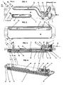
- the illustrated plate heat exchanger is a transmission oil cooler, which can be used for example in a motor vehicle to temper the transmission oil by means of the cooling liquid of the vehicle engine.
- a thermostat - control valve 25 in a housing 22 which is disposed on the one plate, in the embodiment on the cover plate 20, the plate heat exchanger and connected to fastening means 63 with the cover plate 20 .
- the housing 22 has a chamber 28 and a compartment 29.
- the chamber 28 is hydraulically separated from the department 29 .
- the thermostat 23 protrudes, while in the department 29 known elements of the control valve, such as valve rod, valve plate, etc. extend.
- the hydraulic separation can be made by means of seals on the thermostat 23 .
- the thermostat 23 will move the valve stem with the valve disc so that either only cooled coolant KW, only warmed coolant WW or a mixture of HC and WW from the department 29 flow into the inlet channel 5 for the cooling liquid of the plate heat exchanger is, so as to keep the gear oil as possible in the range of the temperature optimum or to bring.
- a transfer passage 21 is formed, through which the oil flows from its outlet channel 8 to its intended exit point oil (off) .
- the inlet channel 7 for the oil was indicated only at the nozzle oil (on) .
- the oil flows through the flow channels 1 in the plate heat exchanger from the inlet channel 7 to the outlet channel eighth
- a cutout 50 with a flow guide member 51 to guide the oil in the chamber 28 and the thermostat 23 , which in the Fig. 3 indicated by a dashed arrow.
- the other dashed arrows indicate the flow of the oil and the solid arrows indicate the flow of the cooling liquid, which will be discussed in more detail below.
- the cooling liquid flows into the inlet channel 5 . It is distributed there in a partial flow T1 , which enters there into the flow channels 2 for the cooling liquid. In the Fig. 3 only a single arrow T1 was drawn.
- the other partial flow T2 flows through the transfer channel 11 formed in the other plate, in the exemplary embodiment in the base plate 10 , to the diametral end of the plate heat exchanger.
- a second inlet channel 5.1 is formed, via which the partial flow T2 has access to the flow channels 2 in order to arrive in the competing flow direction with the partial flow T1 to the outlet channel 6 .
- the outlet channel 6 is arranged approximately in the middle of the plate heat exchanger. From the outlet channel 6 , the cooling liquid flows into a cover plate 20 arranged on the second transfer channel 30, which leads to the outlet nozzle 40 for cooling liquid W (off) .
- the outlet nozzle 40 and the outlet channel 6 are spaced apart. It is understood that in a possible reversal of the flow through the partial flows T1 and T2 have divergent flow direction.
- the division of the cooling liquid flow into the partial flows T1 and T2 can be influenced by known design measures, such as the dimensioning of the flow channels 2 and the transfer channels 11 and 30 or by appropriate choice of the channel lengths in the desired direction.
- the invention in plate heat exchangers can be used, which have a relatively small number of flow channels 1, 2 at a fairly large length thereof to reduce the pressure loss.
- the cover plate 20 of the plate heat exchanger has a projection 60 which projects beyond the stack formed of heat exchanger plates 3 .
- This projection 60 is used in particular to be able to make a vibration-damping attachment 61, 62 of the plate heat exchanger.
- the outlet channel 6 for the cooling liquid is covered by the thermostat control valve 25 .
- the Alternativworschlag differs from the first proposal in that the entire coolant flow first enters the transfer passage 11 and distributed to the two diametral ends of the plate heat exchanger to enter there into the inlet channels 5, 5.1 .
- the partial flows T1 and T2 form in the inlet channel 5 .
Landscapes
- Engineering & Computer Science (AREA)
- General Engineering & Computer Science (AREA)
- Mechanical Engineering (AREA)
- Physics & Mathematics (AREA)
- Thermal Sciences (AREA)
- Heat-Exchange Devices With Radiators And Conduit Assemblies (AREA)
Claims (9)
- Echangeur de chaleur à plaques, par exemple refroidisseur d'huile de boîte de vitesses, dans lequel
l'huile de boîte de vitesses échange de la chaleur avec un liquide,
l'échangeur de chaleur à plaques étant constitué de plaques (3) d'échangeur de chaleur empilées les unes dans les autres et formant des canaux d'écoulement (1, 2) distincts,
les plaques présentant toutes des ouvertures (4) qui forment des canaux (5, 6, 7, 8) dans la pile de plaques (3) d'échangeur de chaleur, ces canaux servant à amener et évacuer les fluides,
l'échangeur de chaleur présentant au moins une plaque supérieure (20) et au moins une plaque inférieure (10) ainsi qu'un canal de transfert (21) formé sur la plaque supérieure (20) ou sur la plaque inférieure (10) pour guider un fluide vers une position souhaitée d'amenée ou d'évacuation,
le canal de transfert (21) étant prévu sur l'une des plaques (10 ou 20) pour l'un des fluides, un canal de guidage (11) qui sert à guider l'autre fluide étant formé sur la plaque ou sur l'autre plaque (10 ou 20),
caractérisé en ce que
une soupape de régulation thermostatique (25) est disposée dans un boîtier (22) sur le canal de transfert (21) de l'une des plaques (10 ou 20), son thermostat (23) entrant en contact avec un fluide, de préférence l'huile, par l'intermédiaire d'une découpe (50) ménagée dans le canal de transfert (21). - Echangeur de chaleur à plaques selon la revendication 1, caractérisé en ce que le canal de guidage (11) prévu sur l'autre plaque (10 ou 20) est destiné de préférence au liquide, le canal de transfert (21) prévu dans une des plaques (10 ou 20) étant prévu pour l'huile.
- Echangeur de chaleur à plaques selon la revendication 1, caractérisé en ce qu'un deuxième canal de transfert (30) prévu de préférence pour le liquide est formé sur une des plaques (10 ou 20).
- Echangeur de chaleur à plaques selon la revendication 1, caractérisé en ce que les canaux d'écoulement (1) prévus pour l'un des fluides (de préférence l'huile) dans l'échangeur de chaleur à plaques peuvent être traversés dans une direction sur sensiblement la totalité de la longueur de l'échangeur de chaleur à plaques, des canaux d'écoulement (2) séparés des premiers et prévus pour l'autre fluide (de préférence un liquide de refroidissement) pouvant être traversés dans l'autre sens, l'autre fluide étant divisé dans son canal d'entrée (5) en deux écoulements partiels (T1, T2), un des écoulements partiels (T1) pénétrant par le canal d'entrée (5) dans ses canaux d'écoulement (2) et l'autre écoulement partiel (T2) s'écoulant par le canal de guidage (11) vers l'extrémité opposée de l'échangeur de chaleur à plaques pour y pénétrer dans les canaux d'écoulement (2) qui lui sont associés de telle sorte que les deux écoulements partiels (T1, T2) de l'autre fluide présentent dans l'échangeur de chaleur à plaques des directions d'écoulement concurrentes et que les écoulements partiels (T1, T2) possèdent des directions d'écoulement divergentes en cas d'inversion du sens d'écoulement.
- Echangeur de chaleur à plaques selon les revendications 1 et 4, caractérisé en ce que les écoulements partiels (T1, T2) concurrents ou divergents aboutissent sensiblement au milieu de l'échangeur de chaleur à plaques ou s'écoulent dans des directions divergentes et possèdent à cet effet un canal commun d'entrée ou de sortie (6).
- Echangeur de chaleur à plaques selon les revendications 1, 3, 4 ou 5, caractérisé en ce que le canal de sortie (6) débouche dans le deuxième canal de guidage (30) qui conduit à une tubulure de sortie (40) disposée à distance du canal de sortie (6).
- Echangeur de chaleur à plaques selon les revendications 1 et 2, caractérisé en ce que le boîtier (22) de la soupape de régulation thermostatique (25) présente un raccord (26) pour un liquide froid et un autre raccord (27) pour un liquide chaud et en ce que selon la température de l'huile, une température du liquide qui contribue à maintenir la température de l'huile au niveau de son optimum peut être établie en fonction de la température de l'huile.
- Echangeur de chaleur à plaques selon les revendications 1, 2 et 7, caractérisé en ce que le boîtier (22) de la soupape de régulation thermostatique (25) présente une chambre (28) pour l'huile dans laquelle l'huile est en contact avec le thermostat (23), en ce qu'une dérivation (29) prévue pour le liquide est raccordée hydrauliquement à un canal d'amenée de l'échangeur de chaleur à plaques et dans laquelle les raccords (26, 27) prévus pour les écoulements de liquide qui présentent différentes températures y débouchent.
- Echangeur de chaleur à plaques selon les revendications 1, 2, 7 et 8, caractérisé en ce qu'un élément (51) de déviation d'écoulement est disposé dans la découpe (50) pour guider l'huile dans la chambre (28).
Applications Claiming Priority (2)
| Application Number | Priority Date | Filing Date | Title |
|---|---|---|---|
| DE200410004975 DE102004004975B4 (de) | 2004-01-31 | 2004-01-31 | Plattenwärmeübertrager |
| DE102004004975 | 2004-01-31 |
Publications (3)
| Publication Number | Publication Date |
|---|---|
| EP1559980A1 EP1559980A1 (fr) | 2005-08-03 |
| EP1559980B1 true EP1559980B1 (fr) | 2012-05-23 |
| EP1559980B2 EP1559980B2 (fr) | 2022-05-18 |
Family
ID=34638826
Family Applications (1)
| Application Number | Title | Priority Date | Filing Date |
|---|---|---|---|
| EP05000457.1A Ceased EP1559980B2 (fr) | 2004-01-31 | 2005-01-12 | Echangeur de chaleur à plaques |
Country Status (3)
| Country | Link |
|---|---|
| US (1) | US7748442B2 (fr) |
| EP (1) | EP1559980B2 (fr) |
| DE (1) | DE102004004975B4 (fr) |
Cited By (2)
| Publication number | Priority date | Publication date | Assignee | Title |
|---|---|---|---|---|
| DE102015221528A1 (de) | 2015-11-03 | 2017-05-04 | Mahle International Gmbh | Wärmeübertragermodul |
| EP4297251A1 (fr) * | 2022-06-21 | 2023-12-27 | Valeo eAutomotive Germany GmbH | Unité de commande électrique avec concept de refroidissement amélioré |
Families Citing this family (34)
| Publication number | Priority date | Publication date | Assignee | Title |
|---|---|---|---|---|
| EP1500896A3 (fr) * | 2003-07-23 | 2009-12-16 | Invensys APV A/S | Elément de couplage pour échangeur de chaleur |
| US8127137B2 (en) | 2004-03-18 | 2012-02-28 | Digimarc Corporation | Watermark payload encryption for media including multiple watermarks |
| GB0411870D0 (en) * | 2004-05-27 | 2004-06-30 | Hansen Transmissions Int | Water cooling device |
| DE102005048294A1 (de) * | 2005-10-08 | 2007-04-12 | Modine Manufacturing Co., Racine | Gelöteter Wärmetauscher und Herstellungsverfahren |
| US7753105B2 (en) * | 2006-05-16 | 2010-07-13 | Delphi Technologies, Inc. | Liquid cooled condenser having an integrated heat exchanger |
| DE102006030790A1 (de) * | 2006-06-30 | 2008-01-03 | Zf Friedrichshafen Ag | Wärmetauscher mit integriertem Bypass-Ventil |
| DE102008031684B4 (de) * | 2008-07-04 | 2020-02-06 | Mahle International Gmbh | Kühleinrichtung |
| EP2251631A1 (fr) * | 2009-05-11 | 2010-11-17 | SPX APV Danmark A/S | Unité de chauffage et son procédé de fabrication |
| JP5694712B2 (ja) * | 2010-09-10 | 2015-04-01 | 株式会社マーレ フィルターシステムズ | オイルクーラ |
| FR2967248B1 (fr) * | 2010-11-10 | 2015-01-23 | Valeo Systemes Thermiques | Echangeur de chaleur fluide/fluide |
| US9239195B2 (en) * | 2011-04-26 | 2016-01-19 | Hyundai Motor Company | Heat exchanger for vehicle |
| KR101283591B1 (ko) * | 2011-09-19 | 2013-07-05 | 현대자동차주식회사 | 차량용 열교환기 |
| US9945623B2 (en) | 2012-05-31 | 2018-04-17 | Dana Canada Corporation | Heat exchanger assemblies with integrated valve |
| US10619530B2 (en) | 2015-01-26 | 2020-04-14 | Modine Manufacturing Company | Thermal management unit for vehicle powertrain |
| US10087793B2 (en) | 2015-01-26 | 2018-10-02 | Modine Manufacturing Company | Thermal management unit for vehicle powertrain |
| US9920829B2 (en) * | 2015-03-10 | 2018-03-20 | Zf Friedrichshafen Ag | Cooler for a marine transmission gearbox |
| DE102015207593A1 (de) | 2015-04-24 | 2016-10-27 | Mahle International Gmbh | Ölkühler |
| JP2017015278A (ja) * | 2015-06-29 | 2017-01-19 | カルソニックカンセイ株式会社 | 熱交換器 |
| JP6086132B2 (ja) * | 2015-07-28 | 2017-03-01 | トヨタ自動車株式会社 | 車両用熱交換器 |
| CN106481436B (zh) * | 2015-08-25 | 2020-05-15 | 康明斯公司 | 用于发动机的滤头的冷却组件 |
| DE102015216481A1 (de) * | 2015-08-28 | 2017-03-02 | Volkswagen Aktiengesellschaft | Wärmetauscher in Plattenbauweise mit Bypass sowie Verfahren zur Herstellung eines Wärmetauschers in Plattenbauweise mit Bypass |
| JP6390574B2 (ja) * | 2015-09-29 | 2018-09-19 | マツダ株式会社 | 変速機及びその製造方法 |
| WO2018035614A1 (fr) | 2016-08-26 | 2018-03-01 | Dana Canada Corporation | Mécanisme de positionnement pour ensemble échangeur de chaleur |
| JP6828151B2 (ja) * | 2016-11-09 | 2021-02-10 | 杭州三花研究院有限公司Hangzhou Sanhua Research Institute Co.,Ltd. | 流体熱交換アセンブリ及び車両熱管理システム |
| US10520075B2 (en) * | 2017-05-31 | 2019-12-31 | Mahle International Gmbh | Apparatus for controlling the temperature of an oil cooler in a motor vehicle |
| DE102018102542A1 (de) * | 2018-01-29 | 2019-08-01 | Woco Industrietechnik Gmbh | Vorrichtung zur Handhabung von Fluiden sowie Verfahren zur Herstellung derselben |
| US10900557B2 (en) | 2018-11-13 | 2021-01-26 | Dana Canada Corporation | Heat exchanger assembly with integrated valve with pressure relief feature for hot and cold fluids |
| JP7171453B2 (ja) * | 2019-01-18 | 2022-11-15 | 株式会社ティラド | サーモバルブ一体型のオイルクーラまたはオイルウォーマ |
| DE102020203892A1 (de) * | 2019-03-29 | 2020-10-01 | Dana Canada Corporation | Tauschermodul mit einem adaptermodul zum direkten anbau an einer fahrzeugkomponente |
| DE102020204271A1 (de) * | 2019-04-05 | 2020-10-08 | Dana Canada Corporation | Wärmetauscheranordnung mit integriertem Ventil und Druckbypass |
| US12247795B2 (en) * | 2019-07-31 | 2025-03-11 | Denso International America, Inc. | Heat exchanger with jumper pipe |
| DE102022202732A1 (de) | 2022-03-21 | 2023-09-21 | Mahle International Gmbh | Stapelscheiben-Wärmeübertrager für ein Thermomanagementmodul |
| FR3134883A1 (fr) * | 2022-04-22 | 2023-10-27 | Valeo Systemes Thermiques | Support pour module de gestion des fluides pour un véhicule notamment automobile et module de gestion des fluides comportant un tel support |
| US12550290B2 (en) * | 2023-10-12 | 2026-02-10 | Quanta Computer Inc. | Cold plate with streamlined coolant tubes |
Family Cites Families (33)
| Publication number | Priority date | Publication date | Assignee | Title |
|---|---|---|---|---|
| US1992097A (en) * | 1933-04-04 | 1935-02-19 | Seligman Richard | Surface heat exchange apparatus for fluids |
| US4303124A (en) * | 1979-06-04 | 1981-12-01 | The A.P.V. Company Limited | Plate heat exchanger |
| US4503908A (en) * | 1979-10-01 | 1985-03-12 | Rockwell International Corporation | Internally manifolded unibody plate for a plate/fin-type heat exchanger |
| JPS6113178U (ja) * | 1984-06-28 | 1986-01-25 | 株式会社 土屋製作所 | ハウジングレス熱交換器 |
| US4708199A (en) * | 1985-02-28 | 1987-11-24 | Kabushiki Kaisha Tsuchiya Seisakusho | Heat exchanger |
| JPH073315B2 (ja) * | 1985-06-25 | 1995-01-18 | 日本電装株式会社 | 熱交換器 |
| JP2737987B2 (ja) * | 1989-03-09 | 1998-04-08 | アイシン精機株式会社 | 積層型蒸発器 |
| DE3938253A1 (de) * | 1989-11-17 | 1991-05-23 | Behr Gmbh & Co | Oelkuehler fuer eine brennkraftmaschine |
| FR2656412B1 (fr) * | 1989-12-21 | 1995-02-17 | Valeo Thermique Moteur Sa | Echangeur de chaleur a lames, en particulier pour le refroidissement de l'huile de lubrification d'un vehicule automobile. |
| JP2521328Y2 (ja) | 1990-08-06 | 1996-12-25 | カルソニック株式会社 | 自動変速機用オイルクーラ |
| US5078209A (en) * | 1991-02-06 | 1992-01-07 | Modine Manufacturing Co. | Heat exchanger assembly |
| JP2558019Y2 (ja) * | 1992-09-24 | 1997-12-17 | カルソニック株式会社 | オイルクーラ |
| US5464056A (en) * | 1992-12-21 | 1995-11-07 | Calsonic Corporation | Housingless type oil cooler and method for producing the same |
| IT1271978B (it) * | 1993-03-05 | 1997-06-10 | Giannoni Srl | Gruppo scambiatore a piastre dispositivo di controllo e relativo scambiatore. |
| DE9309741U1 (de) * | 1993-06-30 | 1993-08-26 | Filterwerk Mann & Hummel Gmbh, 71638 Ludwigsburg | Wärmetauscher |
| JP3663981B2 (ja) * | 1999-06-30 | 2005-06-22 | 株式会社デンソー | 熱交換器及びそのろう付け方法 |
| DE19519740B4 (de) * | 1995-06-02 | 2005-04-21 | Mann + Hummel Gmbh | Wärmetauscher |
| SE9502189D0 (sv) * | 1995-06-16 | 1995-06-16 | Tetra Laval Holdings & Finance | Plattvärmeväxlare |
| EP0787929B1 (fr) † | 1996-02-01 | 2001-04-11 | Bayerische Motoren Werke Aktiengesellschaft, Patentabteilung AJ-3 | Dispositif pour tempérer la température de l'huile de transmission d'un véhicule automobile |
| DE19628561C1 (de) * | 1996-07-16 | 1997-09-04 | Laengerer & Reich Gmbh & Co | Plattenwärmetauscher |
| DE19637817A1 (de) * | 1996-09-17 | 1998-03-19 | Laengerer & Reich Gmbh & Co | Einrichtung und Verfahren zum Kühlen und Vorwärmen |
| DE19654362B4 (de) * | 1996-12-24 | 2007-12-06 | Behr Gmbh & Co. Kg | Wärmeübertrageranordnung |
| DE19654365B4 (de) * | 1996-12-24 | 2007-09-27 | Behr Gmbh & Co. Kg | Plattenwärmeübertrager |
| DE19707647B4 (de) * | 1997-02-26 | 2007-03-01 | Behr Gmbh & Co. Kg | Scheibenkühler |
| DE19709601C5 (de) * | 1997-03-08 | 2007-02-01 | Behr Industry Gmbh & Co. Kg | Plattenwärmeübertrager |
| DE19750814C5 (de) * | 1997-11-17 | 2005-08-18 | Modine Manufacturing Co., Racine | Wärmetauscher, insbesondere Ölkühler |
| CA2260890A1 (fr) * | 1999-02-05 | 2000-08-05 | Long Manufacturing Ltd. | Echangeurs de chaleur fermes |
| FR2790073B1 (fr) * | 1999-02-24 | 2001-06-08 | Mer Joseph Marie Le | Echangeur thermique a plaques, a vanne integree |
| CA2272804C (fr) * | 1999-05-28 | 2004-07-20 | Long Manufacturing Ltd. | Echangeur de chaleur muni d'un canal de derivation |
| DE10019029C5 (de) † | 2000-04-18 | 2017-11-23 | Mahle International Gmbh | Vorrichtung zum Kühlen und/oder Temperieren von Öl |
| CA2383649C (fr) * | 2002-04-24 | 2009-08-18 | Long Manufacturing Ltd. | Plaque de scellement a couvercle inverse pour echangeur thermique |
| DE10328638A1 (de) * | 2003-06-26 | 2005-01-20 | Modine Manufacturing Co., Racine | Wärmetauscher in gehäuseloser Plattenbauweise |
| US7377308B2 (en) * | 2006-05-09 | 2008-05-27 | Modine Manufacturing Company | Dual two pass stacked plate heat exchanger |
-
2004
- 2004-01-31 DE DE200410004975 patent/DE102004004975B4/de not_active Expired - Lifetime
-
2005
- 2005-01-12 EP EP05000457.1A patent/EP1559980B2/fr not_active Ceased
- 2005-01-28 US US11/046,512 patent/US7748442B2/en active Active
Cited By (2)
| Publication number | Priority date | Publication date | Assignee | Title |
|---|---|---|---|---|
| DE102015221528A1 (de) | 2015-11-03 | 2017-05-04 | Mahle International Gmbh | Wärmeübertragermodul |
| EP4297251A1 (fr) * | 2022-06-21 | 2023-12-27 | Valeo eAutomotive Germany GmbH | Unité de commande électrique avec concept de refroidissement amélioré |
Also Published As
| Publication number | Publication date |
|---|---|
| EP1559980B2 (fr) | 2022-05-18 |
| DE102004004975A1 (de) | 2005-08-18 |
| EP1559980A1 (fr) | 2005-08-03 |
| DE102004004975B4 (de) | 2015-04-23 |
| US7748442B2 (en) | 2010-07-06 |
| US20050205236A1 (en) | 2005-09-22 |
Similar Documents
| Publication | Publication Date | Title |
|---|---|---|
| EP1559980B1 (fr) | Echangeur de chaleur à plaques | |
| EP1152204B1 (fr) | Echangeur de chaleur à plaques | |
| EP2205922B1 (fr) | Échangeur thermique, notamment refroidisseur à huile | |
| DE112017002349B4 (de) | Wärmetauscher | |
| EP3119623B1 (fr) | Module de chauffage et de refroidissement | |
| DE19750814C5 (de) | Wärmetauscher, insbesondere Ölkühler | |
| EP0828980B1 (fr) | Echangeur de chaleur | |
| DE102020204271A1 (de) | Wärmetauscheranordnung mit integriertem Ventil und Druckbypass | |
| DE10152363A1 (de) | Gehäuseloser Plattenwärmetauscher | |
| DE19709601C5 (de) | Plattenwärmeübertrager | |
| DE102013220031A1 (de) | Wärmeübertrager | |
| WO2004005832A1 (fr) | Dispositif pour l'echange de chaleur entre des substances pouvant s'ecouler | |
| DE112011104558T5 (de) | Fluidströmungsmischbox mit Fluidströmungsregeleinrichtung | |
| EP0200809A2 (fr) | Filtre à huile avec un échangeur de chaleur intégré | |
| DE102007054703B4 (de) | Wärmetauscher | |
| DE102017219433A1 (de) | Wärmeübertrager für einen Verbrennungsmotor | |
| DE69924647T2 (de) | Plattenwärmetauscher mit integriertem ventil | |
| EP1870655A2 (fr) | Unité de transmission de la chaleur pour un moteur à combustion interne | |
| DE10049890B4 (de) | Stapelscheiben-Wärmeübertrager | |
| EP1687579B1 (fr) | Refroidisseur d'air de suralimentation/d'agent refrigerant | |
| DE4437877C2 (de) | Wärmetauscher, insbesondere Ölkühler | |
| DE102006061440A1 (de) | Kühlflüssigkeitskühler | |
| DE102004020602A1 (de) | Plattenwärmetauscher mit Strömungswegen für drei Wärmetauschfluide | |
| EP0197169B1 (fr) | Radiateur | |
| DE102007027250A1 (de) | Wärmeübertragereinrichtung |
Legal Events
| Date | Code | Title | Description |
|---|---|---|---|
| PUAI | Public reference made under article 153(3) epc to a published international application that has entered the european phase |
Free format text: ORIGINAL CODE: 0009012 |
|
| AK | Designated contracting states |
Kind code of ref document: A1 Designated state(s): AT BE BG CH CY CZ DE DK EE ES FI FR GB GR HU IE IS IT LI LT LU MC NL PL PT RO SE SI SK TR |
|
| AX | Request for extension of the european patent |
Extension state: AL BA HR LV MK YU |
|
| 17P | Request for examination filed |
Effective date: 20060203 |
|
| AKX | Designation fees paid |
Designated state(s): DE ES FR GB IT SE |
|
| 17Q | First examination report despatched |
Effective date: 20070605 |
|
| GRAP | Despatch of communication of intention to grant a patent |
Free format text: ORIGINAL CODE: EPIDOSNIGR1 |
|
| RBV | Designated contracting states (corrected) |
Designated state(s): DE FR GB |
|
| GRAS | Grant fee paid |
Free format text: ORIGINAL CODE: EPIDOSNIGR3 |
|
| GRAA | (expected) grant |
Free format text: ORIGINAL CODE: 0009210 |
|
| AK | Designated contracting states |
Kind code of ref document: B1 Designated state(s): DE FR GB |
|
| REG | Reference to a national code |
Ref country code: GB Ref legal event code: FG4D Free format text: NOT ENGLISH |
|
| REG | Reference to a national code |
Ref country code: DE Ref legal event code: R096 Ref document number: 502005012735 Country of ref document: DE Effective date: 20120712 |
|
| PLBI | Opposition filed |
Free format text: ORIGINAL CODE: 0009260 |
|
| 26 | Opposition filed |
Opponent name: BEHR GMBH & CO. KG Effective date: 20130225 |
|
| PLAX | Notice of opposition and request to file observation + time limit sent |
Free format text: ORIGINAL CODE: EPIDOSNOBS2 |
|
| REG | Reference to a national code |
Ref country code: DE Ref legal event code: R026 Ref document number: 502005012735 Country of ref document: DE Effective date: 20130225 |
|
| PLAF | Information modified related to communication of a notice of opposition and request to file observations + time limit |
Free format text: ORIGINAL CODE: EPIDOSCOBS2 |
|
| PLBB | Reply of patent proprietor to notice(s) of opposition received |
Free format text: ORIGINAL CODE: EPIDOSNOBS3 |
|
| PLAB | Opposition data, opponent's data or that of the opponent's representative modified |
Free format text: ORIGINAL CODE: 0009299OPPO |
|
| R26 | Opposition filed (corrected) |
Opponent name: MAHLE BEHR GMBH & CO. KG Effective date: 20130225 |
|
| REG | Reference to a national code |
Ref country code: FR Ref legal event code: PLFP Year of fee payment: 12 |
|
| PLCK | Communication despatched that opposition was rejected |
Free format text: ORIGINAL CODE: EPIDOSNREJ1 |
|
| APAH | Appeal reference modified |
Free format text: ORIGINAL CODE: EPIDOSCREFNO |
|
| APBM | Appeal reference recorded |
Free format text: ORIGINAL CODE: EPIDOSNREFNO |
|
| APBP | Date of receipt of notice of appeal recorded |
Free format text: ORIGINAL CODE: EPIDOSNNOA2O |
|
| APBQ | Date of receipt of statement of grounds of appeal recorded |
Free format text: ORIGINAL CODE: EPIDOSNNOA3O |
|
| REG | Reference to a national code |
Ref country code: FR Ref legal event code: PLFP Year of fee payment: 13 |
|
| REG | Reference to a national code |
Ref country code: FR Ref legal event code: PLFP Year of fee payment: 14 |
|
| PLAO | Information deleted related to despatch of communication that opposition is rejected |
Free format text: ORIGINAL CODE: EPIDOSDREJ1 |
|
| STAA | Information on the status of an ep patent application or granted ep patent |
Free format text: STATUS: THE PATENT HAS BEEN GRANTED |
|
| PLAY | Examination report in opposition despatched + time limit |
Free format text: ORIGINAL CODE: EPIDOSNORE2 |
|
| APAW | Appeal reference deleted |
Free format text: ORIGINAL CODE: EPIDOSDREFNO |
|
| APAY | Date of receipt of notice of appeal deleted |
Free format text: ORIGINAL CODE: EPIDOSDNOA2O |
|
| APBA | Date of receipt of statement of grounds of appeal deleted |
Free format text: ORIGINAL CODE: EPIDOSDNOA3O |
|
| APBM | Appeal reference recorded |
Free format text: ORIGINAL CODE: EPIDOSNREFNO |
|
| APBP | Date of receipt of notice of appeal recorded |
Free format text: ORIGINAL CODE: EPIDOSNNOA2O |
|
| APBQ | Date of receipt of statement of grounds of appeal recorded |
Free format text: ORIGINAL CODE: EPIDOSNNOA3O |
|
| PLAP | Information related to despatch of examination report in opposition + time limit deleted |
Free format text: ORIGINAL CODE: EPIDOSDORE2 |
|
| APBU | Appeal procedure closed |
Free format text: ORIGINAL CODE: EPIDOSNNOA9O |
|
| PUAH | Patent maintained in amended form |
Free format text: ORIGINAL CODE: 0009272 |
|
| STAA | Information on the status of an ep patent application or granted ep patent |
Free format text: STATUS: PATENT MAINTAINED AS AMENDED |
|
| PGFP | Annual fee paid to national office [announced via postgrant information from national office to epo] |
Ref country code: GB Payment date: 20220127 Year of fee payment: 18 Ref country code: DE Payment date: 20220127 Year of fee payment: 18 |
|
| 27A | Patent maintained in amended form |
Effective date: 20220518 |
|
| AK | Designated contracting states |
Kind code of ref document: B2 Designated state(s): DE FR GB |
|
| REG | Reference to a national code |
Ref country code: DE Ref legal event code: R102 Ref document number: 502005012735 Country of ref document: DE |
|
| PGFP | Annual fee paid to national office [announced via postgrant information from national office to epo] |
Ref country code: FR Payment date: 20220125 Year of fee payment: 18 |
|
| REG | Reference to a national code |
Ref country code: DE Ref legal event code: R119 Ref document number: 502005012735 Country of ref document: DE |
|
| GBPC | Gb: european patent ceased through non-payment of renewal fee |
Effective date: 20230112 |
|
| PG25 | Lapsed in a contracting state [announced via postgrant information from national office to epo] |
Ref country code: GB Free format text: LAPSE BECAUSE OF NON-PAYMENT OF DUE FEES Effective date: 20230112 Ref country code: DE Free format text: LAPSE BECAUSE OF NON-PAYMENT OF DUE FEES Effective date: 20230801 |
|
| PG25 | Lapsed in a contracting state [announced via postgrant information from national office to epo] |
Ref country code: FR Free format text: LAPSE BECAUSE OF NON-PAYMENT OF DUE FEES Effective date: 20230131 |