EP2354871A2 - Verfahren zur Bearbeitung zwischen profilierten Oberflächen mit becherförmigem Werkzeug - Google Patents
Verfahren zur Bearbeitung zwischen profilierten Oberflächen mit becherförmigem Werkzeug Download PDFInfo
- Publication number
- EP2354871A2 EP2354871A2 EP11152523A EP11152523A EP2354871A2 EP 2354871 A2 EP2354871 A2 EP 2354871A2 EP 11152523 A EP11152523 A EP 11152523A EP 11152523 A EP11152523 A EP 11152523A EP 2354871 A2 EP2354871 A2 EP 2354871A2
- Authority
- EP
- European Patent Office
- Prior art keywords
- abrasive disk
- airfoils
- rotor surface
- orientations
- machining
- Prior art date
- Legal status (The legal status is an assumption and is not a legal conclusion. Google has not performed a legal analysis and makes no representation as to the accuracy of the status listed.)
- Withdrawn
Links
Images


Classifications
-
- G—PHYSICS
- G05—CONTROLLING; REGULATING
- G05B—CONTROL OR REGULATING SYSTEMS IN GENERAL; FUNCTIONAL ELEMENTS OF SUCH SYSTEMS; MONITORING OR TESTING ARRANGEMENTS FOR SUCH SYSTEMS OR ELEMENTS
- G05B19/00—Program-control systems
- G05B19/02—Program-control systems electric
- G05B19/18—Numerical control [NC], i.e. automatically operating machines, in particular machine tools, e.g. in a manufacturing environment, so as to execute positioning, movement or co-ordinated operations by means of program data in numerical form
- G05B19/188—Numerical control [NC], i.e. automatically operating machines, in particular machine tools, e.g. in a manufacturing environment, so as to execute positioning, movement or co-ordinated operations by means of program data in numerical form characterised by special applications and not provided for in the relevant subclasses, (e.g. making dies, filament winding)
-
- B—PERFORMING OPERATIONS; TRANSPORTING
- B24—GRINDING; POLISHING
- B24B—MACHINES, DEVICES, OR PROCESSES FOR GRINDING OR POLISHING; DRESSING OR CONDITIONING OF ABRADING SURFACES; FEEDING OF GRINDING, POLISHING, OR LAPPING AGENTS
- B24B19/00—Single-purpose machines or devices for particular grinding operations not covered by any other main group
- B24B19/14—Single-purpose machines or devices for particular grinding operations not covered by any other main group for grinding turbine blades, propeller blades or the like
-
- G—PHYSICS
- G05—CONTROLLING; REGULATING
- G05B—CONTROL OR REGULATING SYSTEMS IN GENERAL; FUNCTIONAL ELEMENTS OF SUCH SYSTEMS; MONITORING OR TESTING ARRANGEMENTS FOR SUCH SYSTEMS OR ELEMENTS
- G05B2219/00—Program-control systems
- G05B2219/30—Nc systems
- G05B2219/45—Nc applications
- G05B2219/45147—Machining blade, airfoil
-
- G—PHYSICS
- G05—CONTROLLING; REGULATING
- G05B—CONTROL OR REGULATING SYSTEMS IN GENERAL; FUNCTIONAL ELEMENTS OF SUCH SYSTEMS; MONITORING OR TESTING ARRANGEMENTS FOR SUCH SYSTEMS OR ELEMENTS
- G05B2219/00—Program-control systems
- G05B2219/30—Nc systems
- G05B2219/50—Machine tool, machine tool null till machine tool work handling
- G05B2219/50353—Tool, probe inclination, orientation to surface, posture, attitude
-
- Y—GENERAL TAGGING OF NEW TECHNOLOGICAL DEVELOPMENTS; GENERAL TAGGING OF CROSS-SECTIONAL TECHNOLOGIES SPANNING OVER SEVERAL SECTIONS OF THE IPC; TECHNICAL SUBJECTS COVERED BY FORMER USPC CROSS-REFERENCE ART COLLECTIONS [XRACs] AND DIGESTS
- Y10—TECHNICAL SUBJECTS COVERED BY FORMER USPC
- Y10T—TECHNICAL SUBJECTS COVERED BY FORMER US CLASSIFICATION
- Y10T29/00—Metal working
- Y10T29/49—Method of mechanical manufacture
- Y10T29/49316—Impeller making
- Y10T29/4932—Turbomachine making
- Y10T29/49325—Shaping integrally bladed rotor
Definitions
- This disclosure generally relates to a method of machining between contoured surfaces. More particularly, this disclosure relates to a method of machining a rotor disk surface between turbine blades.
- a turbine includes a plurality of airfoils affixed or integrally formed as part of a rotor.
- Each airfoil includes a contoured shape.
- An integrally bladed rotor (IBR) includes airfoils disposed about an outer perimeter of the rotor. The rotor and blades are formed as one part. Therefore any finishing is performed on the rotor with the blades.
- a surface between the contoured blades is a challenging surface to machine. Accordingly, it is desirable to design and develop methods of machining this surface.
- a disclosed method of machining a rotor disk includes the process steps of detecting accessible contact areas on a rotor surface and corresponding abrasive disk orientation at contact points within the contact area. The method utilizes the detected accessible area and orientations to map a machining path and corresponding abrasive disk movements. The mapped machining path and detected accessible area is then utilized to generate machine tool executable instructions for driving the abrasive disk during machining operations.
- an integrated bladed rotor (IBR) 10 includes a plurality of integrally formed airfoils 14 that extend radial outward from a disk 12.
- the complex shape of the rotor 10 is finish machined with a grinding operation.
- the example grinding operation utilizes an abrasive disk 18 with a relatively large diameter 38 and a grinding surface 20 disposed at a tip of the disk wall 32.
- a rotor surface 16 between adjacent airfoils 14 is finish machined using the abrasive disk 12 to provide a desired surface finish and shape. This grinding operation is complicated by the close proximity to the adjacent airfoils 14.
- the abrasive disk 18 includes a wall length 40 and thickness 34 that provide desired accessibility to the rotor surface 16 between the two airfoils 14. Moreover, an angle 36 between the center portion of the disk 18 and the walls 32 further provides desired accessibility to the rotor surface 16. The length 40 and angle 36 are provided dependent on a size and shape of the airfoils 14.
- the example machining operation utilizes the rotating abrasive disk 18 that is moved between adjacent airfoils 14 to contact the rotor surface 16, but not contact the adjacent airfoils 14. Accordingly, the possible area on the rotor surface 16 that is accessible by the abrasive disk 18 is limited and is determined according to a disclosed example method.
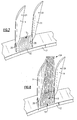
- the abrasive disk 18 rotates during machining to provide the desired material removal and surface finish. Movement of the abrasive disk 18 between the airfoils 14 is possible about a roll axis 28 ( Figure 3 ) and a yaw axis 42 ( Figures 4 and 5 ). Movement about the roll axis 28 is schematically indicated at 30 and is limited by the position and height of the airfoils 14. Each of the airfoils 14 includes an inner contour 24 and an outer contour 26. The inner and outer contours 24 and 26 are formed and finished in a separate machining operation. Movement about the roll axis 28 comprises tilting of the abrasive disk 18 at an angle relative to normal about the roll axis 28. Movement of the abrasive disk 18 about the roll axis 28 while remaining in place at a contact point 22 is limited by adjacent airfoils 14.
- the abrasive disk 18 is movable about the yaw axis 42 as indicated at 44 and comprises twisting of the abrasive disk 18 while maintaining point contact at the contact point 22. Movement about the yaw axis 42 is again limited by the adjacent airfoils 14.
- the yaw axis is defined as a line passing through the contact point where the cutter touches the part and normal to the part surface at that point.
- the limits of movement of the abrasive disk 18 about the roll axis 28 and the yaw axis 42 provide a range of possible abrasive disk orientations that can be utilized during machining of the rotor surface 16. Determining the entire range of possible abrasive disk orientations for each point on the rotor surface 16 provides the information necessary to generate a machining path and instructions executable by a machine tool for maneuvering the abrasive disk 18 into the area between the airfoils 14.
- the accessible area is determined by detecting a range of acceptable orientations of the abrasive disk 18 at multiple contact points 22 along the rotor surface 16 between the airfoils 14.
- the acceptable orientations of the abrasive disk 18 include positions in which the abrasive disk 18 does not contact and/or is spaced apart from the nearest airfoil 14 by a desired clearance.
- Detecting the accessible area and acceptable orientations of the abrasive disk 18 on the rotor surface 16 is performed by placing the abrasive disk 18 into contact or within a desired distance with the rotor surface 16 and incrementally moving the abrasive disk 18 about the roll axis 28 and the yaw axis 42.
- the incremental movement of the abrasive disk 18 results in the determination of outer boundaries of orientations of the abrasive disk 18 at a particular contact point 22.
- the abrasive disk 18 is then moved to a different contact point 22 and another range or incremental movements made until the outer boundaries of contact points with acceptable abrasive disk orientations are mapped.
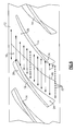
- Figure 6 illustrates an example pattern for the detecting process.
- a centerline 46 between the airfoils 14 along with lines 48 that are transverse to the centerline 48 illustrate the example pattern for detecting acceptable contact points and orientations of the abrasive disk 18.
- the contact points 22 are the contact points 22.
- the possible movement in each of the axis 28 and 42 is determined.
- the possible range of movement about the roll axis 28 is detected and recorded.
- the possible range of movement about the yaw axis 42 is detected and recorded.
- the abrasive disk 18 is rotated about each of the roll axis 28 and the yaw axis until further movement of the abrasive axis would result in less then a minimum allowable clearance with one of the airfoils 14.
- the range of movement in each of the axis 28, 42 is then utilized to determine if each contact point on rotor surface 16 is accessible.
- the detection determination is repeated at successive contact points 22 that approach each airfoil 14.
- the number and location of contact points 22 is determined to provide a desired accuracy and precision. As detection is performed at contact points 22 closer to the each of the airfoils 14, the range of possible abrasive disk orientations becomes more and more limited.
- the spacing of the contact points 22 is illustrated as being substantially uniform, however, the contact points 22 may be closer together as detection is performed at contact points 22 closer and closer to the each of the airfoils.
- the determinations made of abrasive disk 18 orientations at contact points 22 closer to each other provide an increased precision and range of acceptable disk 18 orientations. In other words, smaller increments are utilized to define acceptable orientations and contact points as the outer limits of abrasive disk position and orientation is approached.
- Completion of the detection process produces a range of contact points 22 that can be reached and contacted by the abrasive disk 18 without contacting, or otherwise intruding on a minimal clearance with the airfoils 14.
- a range of acceptable abrasive disk orientations are determined that include acceptable roll and yaw combinations and are recorded.
- Information on the range of contact points and disk orientations possible at each point maps the overall acceptable range of movement for the abrasive disk 18 in machining the rotor surface 16.
- a machining pattern is next determined utilizing the detected range of contact points and corresponding disk orientations.
- the initial step is to define a desired machining pattern.
- an example machining pattern 50 comprises a zig-zag pattern where the machining path is continuous between passes over the rotor surface 16.
- each successive pass of the abrasive disk 18 is connected such that the abrasive disk 18 is placed in contact with the rotor surface only once and until such time as the entire surface of the rotor surface is machined.
- FIG 8 another example machining pattern 52 is disclosed as a zag pattern and includes a plurality of successive machining passes that are each separate from the previous machining pass.
- the abrasive disk 18 is lifted from the rotor surface 16 after each pass started from one side of the rotor surface 16.
- Figures 7 and 8 are examples of possible machining patterns, and other patterns as are known could be utilized.
- the information obtained during the detection process defines a mapped area relative to the rotor disk 10 in which the abrasive disk 18 could move without contacting the airfoils 14.
- the determination of the machining pattern utilizes this information to not only define the machining pattern but also approach paths and retraction paths of the abrasive disk 18.
- the machining pattern is determined by selecting a desired pattern, such as the example zig-zag 50 or zag 52. Depending on the pattern selected, an initial contact point is determined for the machining path. From the initial contact point the middle and end points for each pass is determined in view of the detected range of disk orientations.
- At least one abrasive disk orientation is determined.
- the acceptable abrasive disk orientation is determined by directly utilizing the detected data.
- an acceptable disk orientation can be predicted utilizing the detected data, or a previously determined position.
- the prediction of the disk orientation can also be determined by interpolating a position from the orientation data and data corresponding to surrounding contact points.
- the disk orientation is selected is that orientation including the roll position and the yaw position that is furthest from both of the airfoils 14.
- Each separate contact point is utilized to define the subsequent orientation of the abrasive disk 18 at the next contact point to avoid sudden orientation changes.
- the maximum clearance orientation point may not be utilized for each contact point in order to define a smooth machining path of the abrasive disk 18. Such a smoothing of the position and orientation can be accomplished by numerical averages or other analysis techniques to smooth transition of the abrasive disk 18 along the machining path.
- the machining path also necessarily includes approach and retraction paths of the abrasive disk 18.
- the approach and retraction paths are defined in view of the detected accessible area between the airfoils 14. With defined approach and retraction paths, the machining path is defined.
- the abrasive disk 18 removes material on the rotor surface 16 and therefore the contact points 22 will be disposed at a level indicative of a depth of cut along the rotor surface 16. The depth below the starting surface is factored into the determination of acceptable disk orientations.
- a desired feed rate of the abrasive disk 18 is determined and included with the determined mapped machining path for generation of machine executable instructions.
- movements of the abrasive disk 18 for machining the rotor surface 16 are executed by a machine tool.
- a numerically controlled machine tool requires instructions in a standard format. The information determined concerning the machining path and any other machine parameter are therefore input in a format recognized and useful in generating executable instructions for a numerically controlled machine.
- the disclosed process has been described as it relates to the physical interaction with the abrasive disk 18 and the rotor 10.
- This example process can be accomplished as a computer-implemented method utilizing computer generated solid models indicative of the rotor 10 and the corresponding abrasive disk 18.
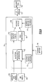
- a computer system 56 is schematically shown and executes the disclosed process with a computer generated model 58 of the example abrasive disk 58 and a computer generated model of the IBR rotor 60.
- the computer system 56 is directed to detect an accessible rotor surface area and corresponding accessible abrasive disk orientations as schematically indicated at 62.
- the instructions and process indicated at 62 provide for orientating the model 58 at successive contact points 22 on the rotor surface 16 represented by the model 60 indicative of the rotor 10.
- a desired search pattern as indicated at 77 is provided as an input for the detection of accessible disk orientations.
- the desires search pattern 77 can include adaptive parameters that set out spacing and increments between contact points 22 and disk orientations.
- the computing system 56 is utilized to orientate the corresponding models to obtain the information indicative of a relative position between the rotor 10 and the abrasive disk 18.
- An intermediate output from the instructions and process indicated at 62 include a set of accessible contact points on the rotor surface indicated at 66 and a set of acceptable disk orientations indicated at 64 at each of the contact points.
- This information is input into a machining module 68 that includes another set of instructions that maps a machining path along the rotor surface 16.
- the module 68 receives the additional input of a desired machining path as indicated at 70.
- the machining path 70 can include any known machining pattern as is desired.
- the selected machining path is tailored to specific applications and rotor configurations.
- the output from the module 68 is a set of instructions 72 that can be utilized to generate machine tool executable instructions.
- the example instructions are in the form of a high level output that is converted using a postprocessor into a specific Numerical Control (NC) format utilized by the machine tool.
- Numerical Control instructions can be provided in various formats, for example RS274d and ISO6983 formats along with any other NC control machine executable instructions.
- the examples set of instructions 72 are thereby usable to generate specific machine tool executable instructions that direct the actions of a NC machine tool 74.
- the example NC machine tool 74 provides for movement of the abrasive disk 18 to machine the rotor surface 16. It should be understood that the format and characteristics of the instructions 72 generated by the computer system can be in any format desired that corresponds with the machine tool utilized for controlling movement and machining with the example abrasive disk 18.
- the computing system 56 used to implement various functionality can be of any known configuration.
- the computing system 56 can include a processor, a memory, and one or more input and/or output (I/O) device interface(s) that are communicatively coupled via a local interface.
- the local interface can include, for example but not limited to, one or more buses and/or other wired or wireless connections.
- the local interface may have additional elements, which are omitted for simplicity, such as controllers, buffers (caches), drivers, repeaters, and receivers to enable communications. Further, the local interface may include address, control, and/or data connections to enable appropriate communications among the aforementioned components.
- the processor may be a hardware device for executing software, particularly software stored in memory or any other storage medium 76 that includes instructions directing the computer system 56 to perform the disclosed process.
- the processor can be a custom made or commercially available processor, a central processing unit (CPU), an auxiliary processor among several processors associated with the computing device, a semiconductor based microprocessor (in the form of a microchip or chip set) or generally any device for executing software instructions.
- the memory can include any one or combination of volatile memory elements (e.g., random access memory (RAM, such as DRAM, SRAM, SDRAM, VRAM, etc.)) and/or nonvolatile memory elements (e.g., ROM, hard drive, tape, CD-ROM, etc.).
- volatile memory elements e.g., random access memory (RAM, such as DRAM, SRAM, SDRAM, VRAM, etc.)
- nonvolatile memory elements e.g., ROM, hard drive, tape, CD-ROM, etc.
- the memory may incorporate electronic, magnetic, optical, and/or other types of storage media.
- the memory can also have a distributed architecture, where various components are situated remotely from one another, but can be accessed by the processor.
- the software in the memory may include one or more separate programs, each of which includes an ordered listing of executable instructions for implementing logical functions.
- a system component embodied as software may also be construed as a source program, executable program (object code), script, or any other entity comprising a set of instructions to be performed.
- the program is translated via a compiler, assembler, interpreter, or the like, which may or may not be included within the memory.
- the Input/Output devices that may be coupled to system I/O Interface(s) may include input devices, for example but not limited to, a keyboard, mouse, scanner, microphone, camera, proximity device, etc. Further, the Input/Output devices may also include output devices, for example but not limited to, a printer, display, etc. Finally, the Input/Output devices may further include devices that communicate both as inputs and outputs, for instance but not limited to, a modulator/demodulator (modem; for accessing another device, system, or network), a radio frequency (RF) or other transceiver, a telephonic interface, a bridge, a router, etc.
- modem for accessing another device, system, or network
- RF radio frequency
- the processor can be configured to execute software stored within the memory, to communicate data to and from the memory, and to generally control operations of the computing system 56 pursuant to the software.
- Software in memory in whole or in part, is read by the processor, perhaps buffered within the processor, and then executed.
- any computer aided modeling method, software and device could be utilized to construct and orientate the models in relative position to each other and to gather data indicative of the acceptable range of movements about the roll and yaw axis.
Landscapes
- Engineering & Computer Science (AREA)
- Human Computer Interaction (AREA)
- Manufacturing & Machinery (AREA)
- Physics & Mathematics (AREA)
- General Physics & Mathematics (AREA)
- Automation & Control Theory (AREA)
- Mechanical Engineering (AREA)
- Finish Polishing, Edge Sharpening, And Grinding By Specific Grinding Devices (AREA)
- Grinding And Polishing Of Tertiary Curved Surfaces And Surfaces With Complex Shapes (AREA)
Applications Claiming Priority (1)
| Application Number | Priority Date | Filing Date | Title |
|---|---|---|---|
| US12/696,540 US20110189924A1 (en) | 2010-01-29 | 2010-01-29 | Method of machining between contoured surfaces with cup shaped tool |
Publications (2)
| Publication Number | Publication Date |
|---|---|
| EP2354871A2 true EP2354871A2 (de) | 2011-08-10 |
| EP2354871A3 EP2354871A3 (de) | 2012-03-28 |
Family
ID=43923615
Family Applications (1)
| Application Number | Title | Priority Date | Filing Date |
|---|---|---|---|
| EP11152523A Withdrawn EP2354871A3 (de) | 2010-01-29 | 2011-01-28 | Verfahren zur Bearbeitung zwischen profilierten Oberflächen mit becherförmigem Werkzeug |
Country Status (2)
| Country | Link |
|---|---|
| US (1) | US20110189924A1 (de) |
| EP (1) | EP2354871A3 (de) |
Cited By (2)
| Publication number | Priority date | Publication date | Assignee | Title |
|---|---|---|---|---|
| CN104503367A (zh) * | 2014-12-11 | 2015-04-08 | 常州奥凡威尔智能技术有限公司 | 一种基于数控加工装置的涡轮叶片加工及在线检测系统 |
| CN108803478A (zh) * | 2018-06-15 | 2018-11-13 | 西安电子科技大学 | 一种航空发动机叶片加工过程退化的轮廓质量控制方法 |
Families Citing this family (7)
| Publication number | Priority date | Publication date | Assignee | Title |
|---|---|---|---|---|
| US8911280B2 (en) * | 2011-01-31 | 2014-12-16 | Apple Inc. | Apparatus for shaping exterior surface of a metal alloy casing |
| US8665160B2 (en) | 2011-01-31 | 2014-03-04 | Apple Inc. | Antenna, shielding and grounding |
| US8587939B2 (en) | 2011-01-31 | 2013-11-19 | Apple Inc. | Handheld portable device |
| WO2014143302A1 (en) * | 2013-03-15 | 2014-09-18 | United Technologies Corporation | Tool for abrasive flow machining of airfoil clusters |
| US9550267B2 (en) | 2013-03-15 | 2017-01-24 | United Technologies Corporation | Tool for abrasive flow machining of airfoil clusters |
| US10220447B2 (en) | 2015-03-08 | 2019-03-05 | Apple Inc. | Polishing and brushing techniques for cylindrical and contoured surfaces |
| DE102021105286A1 (de) * | 2021-03-04 | 2022-09-08 | Kennametal Inc. | Verfahren zur Herstellung eines Frästeils mit einem Senkwerkzeug und Senkwerkzeug |
Citations (1)
| Publication number | Priority date | Publication date | Assignee | Title |
|---|---|---|---|---|
| US20030024825A1 (en) * | 2001-07-31 | 2003-02-06 | Lamphere Michael Scott | Plunge electromachining |
Family Cites Families (25)
| Publication number | Priority date | Publication date | Assignee | Title |
|---|---|---|---|---|
| US4512115A (en) * | 1983-06-07 | 1985-04-23 | United Technologies Corporation | Method for cylindrical grinding turbine engine rotor assemblies |
| US4791575A (en) * | 1986-10-31 | 1988-12-13 | The Pratt & Whitney Company, Inc. | Method for generating axis control data for use in controlling a grinding machine and the like and system therefor |
| US5067876A (en) * | 1990-03-29 | 1991-11-26 | General Electric Company | Gas turbine bladed disk |
| US6120171A (en) * | 1996-06-14 | 2000-09-19 | Mohammad Salim Shaikh | Fully integrated machinable profile based parametric solid modeler |
| US6311100B1 (en) * | 1998-09-14 | 2001-10-30 | Mass. Institute Of Technology | Tool path generator for computer aided manufacturing |
| ATE420272T1 (de) * | 1999-12-20 | 2009-01-15 | Sulzer Metco Ag | Profilierte, als anstreifschicht verwendete oberfläche in strömungsmaschinen |
| CA2426453A1 (en) * | 2000-08-08 | 2002-02-14 | Sdgi Holdings, Inc. (D/B/A Medtronic Sofamor Danek, Inc.) | Improved method and apparatus for stereotactic implantation |
| FR2828824B1 (fr) * | 2001-08-23 | 2003-12-05 | Snecma Moteurs | Procede de fabrication d'un disque aubage monobloc de rotor et disque correspondant |
| DE10156156B4 (de) * | 2001-11-15 | 2005-04-21 | 3M Espe Ag | Verfahren zur Herstellung von Zahnersatz |
| US6554571B1 (en) * | 2001-11-29 | 2003-04-29 | General Electric Company | Curved turbulator configuration for airfoils and method and electrode for machining the configuration |
| JP2003177811A (ja) * | 2001-12-12 | 2003-06-27 | Toyota Motor Corp | 設計支援装置及び方法 |
| US6878035B2 (en) * | 2002-03-22 | 2005-04-12 | Darex Corporation | Tool sharpener |
| DE10219012B4 (de) * | 2002-04-27 | 2004-11-04 | Mtu Aero Engines Gmbh | Fräsverfahren |
| US6935817B2 (en) * | 2002-08-14 | 2005-08-30 | Pratt & Whitney Canada Corp. | Airfoil machining using cup tool |
| JP4316850B2 (ja) * | 2002-09-26 | 2009-08-19 | 森精機興産株式会社 | 複合加工工作機械における加工方法 |
| DE10312224B3 (de) * | 2003-03-19 | 2004-10-28 | Mtu Aero Engines Gmbh | Verfahren zum Herstellen von strömungsbeaufschlagten Bauteilen |
| EP1486289A3 (de) * | 2003-06-12 | 2005-03-09 | Koyo Seiko Co., Ltd. | Verfahren zum Schleifen der Wälzlagereinheit eines Rades |
| DE60314744T2 (de) * | 2003-07-29 | 2008-03-06 | Mtu Aero Engines Gmbh | Herstellungsverfahren insbesondere eines integral beschaufelten Rotors |
| EP1775065B1 (de) * | 2004-08-06 | 2013-03-06 | Horkos Corporation | Rundheitsarbeitsverfahren und rundheitsarbeitsvorrichtung in nc-maschinenwerkzeug |
| US20060275624A1 (en) * | 2005-06-07 | 2006-12-07 | General Electric Company | Method and apparatus for airfoil electroplating, and airfoil |
| US20080131216A1 (en) * | 2006-12-05 | 2008-06-05 | Pratt & Whitney Canada Corp. | Cup mill for airfoils |
| US7303461B1 (en) * | 2006-12-05 | 2007-12-04 | Pratt & Whitney Canada Corp. | Method of machining airfoils by disc tools |
| EP2000258B1 (de) * | 2007-06-07 | 2011-08-24 | Nissan Motor Co., Ltd. | Honverfahren und -vorrichtung |
| US8100655B2 (en) * | 2008-03-28 | 2012-01-24 | Pratt & Whitney Canada Corp. | Method of machining airfoil root fillets |
| US7967659B2 (en) * | 2008-05-15 | 2011-06-28 | United Technologies Corporation | Method of machining integral bladed rotors for a gas turbine engine |
-
2010
- 2010-01-29 US US12/696,540 patent/US20110189924A1/en not_active Abandoned
-
2011
- 2011-01-28 EP EP11152523A patent/EP2354871A3/de not_active Withdrawn
Patent Citations (1)
| Publication number | Priority date | Publication date | Assignee | Title |
|---|---|---|---|---|
| US20030024825A1 (en) * | 2001-07-31 | 2003-02-06 | Lamphere Michael Scott | Plunge electromachining |
Cited By (3)
| Publication number | Priority date | Publication date | Assignee | Title |
|---|---|---|---|---|
| CN104503367A (zh) * | 2014-12-11 | 2015-04-08 | 常州奥凡威尔智能技术有限公司 | 一种基于数控加工装置的涡轮叶片加工及在线检测系统 |
| CN104503367B (zh) * | 2014-12-11 | 2017-06-23 | 常州奥凡威尔智能技术有限公司 | 一种基于数控加工装置的涡轮叶片加工及在线检测系统 |
| CN108803478A (zh) * | 2018-06-15 | 2018-11-13 | 西安电子科技大学 | 一种航空发动机叶片加工过程退化的轮廓质量控制方法 |
Also Published As
| Publication number | Publication date |
|---|---|
| US20110189924A1 (en) | 2011-08-04 |
| EP2354871A3 (de) | 2012-03-28 |
Similar Documents
| Publication | Publication Date | Title |
|---|---|---|
| EP2354871A2 (de) | Verfahren zur Bearbeitung zwischen profilierten Oberflächen mit becherförmigem Werkzeug | |
| JP6553508B2 (ja) | Cncコントローラに組み込まれたcam機能を有するコンピュータ数値制御(cnc)システム及びcnc機械を修正する方法 | |
| US12459040B2 (en) | Hybrid additive and subtractive manufacturing | |
| US8000942B2 (en) | Broach tool design methodology and systems | |
| CN102467112B (zh) | 工具机的加工法 | |
| US20100023157A1 (en) | Methods and systems for fabricating a component | |
| EP4075216B1 (de) | Werkzeugbahnerzeugungsverfahren, werkzeugbahnerzeugungsvorrichtung und steuerung einer werkzeugmaschine | |
| US10884390B2 (en) | Optimized control of a metal-cutting machine tool | |
| KR20250010648A (ko) | 물체의 표면 피팅, 경로 계획 및 표면 처리를 위한 시스템 및 방법 | |
| Yousefian et al. | Point-by-point prediction of cutting force in 3-axis CNC milling machines through voxel framework in digital manufacturing | |
| EP3677972B1 (de) | Verfahren und vorrichtung zum bearbeiten von teilen mit variabler steifheit | |
| JP5969882B2 (ja) | 加工データ一貫生成装置、加工データ一貫生成プログラム及び加工データ一貫生成方法 | |
| Chu et al. | Spline-constrained tool-path planning in five-axis flank machining of ruled surfaces | |
| EP1789898B1 (de) | System, verfahren und computerprogramm zur fräsausführung mit örtlich begrenzter aushöhlung | |
| JP7460750B2 (ja) | 数値制御装置 | |
| JP4225422B2 (ja) | Nc加工システム、ncデータ作成装置、ncデータ作成システム、ncデータ作成方法及びncデータ作成プログラム | |
| JP7740065B2 (ja) | プロセッサシステム、加工経路生成方法およびプログラム | |
| JP5109809B2 (ja) | 機械加工検証支援方法および装置、機械加工検証支援用プログラムおよび記憶媒体 | |
| EP4242755B1 (de) | Informationsverarbeitungsvorrichtung, informationsverarbeitungsverfahren und informationsverarbeitungsprogramm | |
| WO2024084706A1 (ja) | 加工指令修正装置及び加工指令修正方法 | |
| JPH08118202A (ja) | 最大傾斜方向ツリー追跡による曲面体加工物の数値制御ミリング加工方法 | |
| CN121348766A (zh) | 一种基于实时仿真检测的动态抬刀决策与高度优化方法 | |
| Geng et al. | Process Planning for 5-Axis Milling of Sculptured Surfaces Based on Cutter’s Accessibility Analysis | |
| JPH10113846A (ja) | 切削加工方法、切削加工データ作成方法、および切削加工データ作成用プログラム記録媒体 | |
| JPH09190208A (ja) | Ncデータ作成装置 |
Legal Events
| Date | Code | Title | Description |
|---|---|---|---|
| PUAI | Public reference made under article 153(3) epc to a published international application that has entered the european phase |
Free format text: ORIGINAL CODE: 0009012 |
|
| AK | Designated contracting states |
Kind code of ref document: A2 Designated state(s): AL AT BE BG CH CY CZ DE DK EE ES FI FR GB GR HR HU IE IS IT LI LT LU LV MC MK MT NL NO PL PT RO RS SE SI SK SM TR |
|
| AX | Request for extension of the european patent |
Extension state: BA ME |
|
| PUAL | Search report despatched |
Free format text: ORIGINAL CODE: 0009013 |
|
| AK | Designated contracting states |
Kind code of ref document: A3 Designated state(s): AL AT BE BG CH CY CZ DE DK EE ES FI FR GB GR HR HU IE IS IT LI LT LU LV MC MK MT NL NO PL PT RO RS SE SI SK SM TR |
|
| AX | Request for extension of the european patent |
Extension state: BA ME |
|
| RIC1 | Information provided on ipc code assigned before grant |
Ipc: G05B 19/18 20060101AFI20120217BHEP Ipc: B24B 19/14 20060101ALI20120217BHEP Ipc: B23C 3/14 20060101ALI20120217BHEP |
|
| 17P | Request for examination filed |
Effective date: 20120928 |
|
| RAP1 | Party data changed (applicant data changed or rights of an application transferred) |
Owner name: UNITED TECHNOLOGIES CORPORATION |
|
| STAA | Information on the status of an ep patent application or granted ep patent |
Free format text: STATUS: EXAMINATION IS IN PROGRESS |
|
| 17Q | First examination report despatched |
Effective date: 20170315 |
|
| GRAP | Despatch of communication of intention to grant a patent |
Free format text: ORIGINAL CODE: EPIDOSNIGR1 |
|
| STAA | Information on the status of an ep patent application or granted ep patent |
Free format text: STATUS: GRANT OF PATENT IS INTENDED |
|
| INTG | Intention to grant announced |
Effective date: 20200318 |
|
| STAA | Information on the status of an ep patent application or granted ep patent |
Free format text: STATUS: THE APPLICATION IS DEEMED TO BE WITHDRAWN |
|
| 18D | Application deemed to be withdrawn |
Effective date: 20200729 |