EP2355314A1 - Elektrischer Linearmotor - Google Patents
Elektrischer Linearmotor Download PDFInfo
- Publication number
- EP2355314A1 EP2355314A1 EP10001197A EP10001197A EP2355314A1 EP 2355314 A1 EP2355314 A1 EP 2355314A1 EP 10001197 A EP10001197 A EP 10001197A EP 10001197 A EP10001197 A EP 10001197A EP 2355314 A1 EP2355314 A1 EP 2355314A1
- Authority
- EP
- European Patent Office
- Prior art keywords
- stator
- active
- rotor
- linear motor
- linear
- Prior art date
- Legal status (The legal status is an assumption and is not a legal conclusion. Google has not performed a legal analysis and makes no representation as to the accuracy of the status listed.)
- Withdrawn
Links
- 239000011521 glass Substances 0.000 claims abstract description 51
- 238000004804 winding Methods 0.000 claims abstract description 18
- 230000033001 locomotion Effects 0.000 claims description 12
- 230000009471 action Effects 0.000 claims description 2
- 230000000295 complement effect Effects 0.000 claims description 2
- 230000001788 irregular Effects 0.000 claims description 2
- 239000011295 pitch Substances 0.000 description 15
- 238000003825 pressing Methods 0.000 description 10
- 238000007496 glass forming Methods 0.000 description 5
- 238000001816 cooling Methods 0.000 description 3
- 230000004907 flux Effects 0.000 description 3
- 238000000465 moulding Methods 0.000 description 3
- XEEYBQQBJWHFJM-UHFFFAOYSA-N Iron Chemical compound [Fe] XEEYBQQBJWHFJM-UHFFFAOYSA-N 0.000 description 2
- 230000008901 benefit Effects 0.000 description 2
- 230000015572 biosynthetic process Effects 0.000 description 2
- KPLQYGBQNPPQGA-UHFFFAOYSA-N cobalt samarium Chemical compound [Co].[Sm] KPLQYGBQNPPQGA-UHFFFAOYSA-N 0.000 description 2
- 238000010276 construction Methods 0.000 description 2
- 238000010586 diagram Methods 0.000 description 2
- 238000003475 lamination Methods 0.000 description 2
- 239000000696 magnetic material Substances 0.000 description 2
- 239000006060 molten glass Substances 0.000 description 2
- 229910001172 neodymium magnet Inorganic materials 0.000 description 2
- 238000005498 polishing Methods 0.000 description 2
- 229910000938 samarium–cobalt magnet Inorganic materials 0.000 description 2
- QJVKUMXDEUEQLH-UHFFFAOYSA-N [B].[Fe].[Nd] Chemical compound [B].[Fe].[Nd] QJVKUMXDEUEQLH-UHFFFAOYSA-N 0.000 description 1
- 230000005540 biological transmission Effects 0.000 description 1
- 230000000052 comparative effect Effects 0.000 description 1
- 239000004020 conductor Substances 0.000 description 1
- 230000007423 decrease Effects 0.000 description 1
- 230000005520 electrodynamics Effects 0.000 description 1
- 210000004907 gland Anatomy 0.000 description 1
- 229910052742 iron Inorganic materials 0.000 description 1
- 238000010030 laminating Methods 0.000 description 1
- 238000004519 manufacturing process Methods 0.000 description 1
- 239000000463 material Substances 0.000 description 1
- 238000002844 melting Methods 0.000 description 1
- 230000008018 melting Effects 0.000 description 1
- 238000000034 method Methods 0.000 description 1
- 230000009467 reduction Effects 0.000 description 1
- 239000007787 solid Substances 0.000 description 1
- 239000011343 solid material Substances 0.000 description 1
Images
Classifications
-
- H—ELECTRICITY
- H02—GENERATION; CONVERSION OR DISTRIBUTION OF ELECTRIC POWER
- H02K—DYNAMO-ELECTRIC MACHINES
- H02K41/00—Propulsion systems in which a rigid body is moved along a path due to dynamo-electric interaction between the body and a magnetic field travelling along the path
- H02K41/02—Linear motors; Sectional motors
- H02K41/03—Synchronous motors; Motors moving step by step; Reluctance motors
- H02K41/031—Synchronous motors; Motors moving step by step; Reluctance motors of the permanent magnet type
-
- H—ELECTRICITY
- H02—GENERATION; CONVERSION OR DISTRIBUTION OF ELECTRIC POWER
- H02K—DYNAMO-ELECTRIC MACHINES
- H02K5/00—Casings; Enclosures; Supports
- H02K5/04—Casings or enclosures characterised by the shape, form or construction thereof
- H02K5/20—Casings or enclosures characterised by the shape, form or construction thereof with channels or ducts for flow of cooling medium
-
- C—CHEMISTRY; METALLURGY
- C03—GLASS; MINERAL OR SLAG WOOL
- C03B—MANUFACTURE, SHAPING, OR SUPPLEMENTARY PROCESSES
- C03B11/00—Pressing molten glass or performed glass reheated to equivalent low viscosity without blowing
- C03B11/16—Gearing or controlling mechanisms specially adapted for glass presses
-
- C—CHEMISTRY; METALLURGY
- C03—GLASS; MINERAL OR SLAG WOOL
- C03B—MANUFACTURE, SHAPING, OR SUPPLEMENTARY PROCESSES
- C03B9/00—Blowing glass; Production of hollow glass articles
- C03B9/13—Blowing glass; Production of hollow glass articles in gob feeder machines
- C03B9/193—Blowing glass; Production of hollow glass articles in gob feeder machines in "press-and-blow" machines
- C03B9/1932—Details of such machines, e.g. plungers or plunger mechanisms for the press-and-blow machine, cooling of plungers
- C03B9/1938—Electrical means for the displacement of the plunger
-
- C—CHEMISTRY; METALLURGY
- C03—GLASS; MINERAL OR SLAG WOOL
- C03B—MANUFACTURE, SHAPING, OR SUPPLEMENTARY PROCESSES
- C03B9/00—Blowing glass; Production of hollow glass articles
- C03B9/30—Details of blowing glass; Use of materials for the moulds
- C03B9/40—Gearing or controlling mechanisms specially adapted for glass-blowing machines
- C03B9/41—Electric or electronic systems
-
- H—ELECTRICITY
- H02—GENERATION; CONVERSION OR DISTRIBUTION OF ELECTRIC POWER
- H02K—DYNAMO-ELECTRIC MACHINES
- H02K1/00—Details of the magnetic circuit
- H02K1/06—Details of the magnetic circuit characterised by the shape, form or construction
-
- H—ELECTRICITY
- H02—GENERATION; CONVERSION OR DISTRIBUTION OF ELECTRIC POWER
- H02K—DYNAMO-ELECTRIC MACHINES
- H02K2201/00—Specific aspects not provided for in the other groups of this subclass relating to the magnetic circuits
- H02K2201/03—Machines characterised by aspects of the air-gap between rotor and stator
-
- H—ELECTRICITY
- H02—GENERATION; CONVERSION OR DISTRIBUTION OF ELECTRIC POWER
- H02K—DYNAMO-ELECTRIC MACHINES
- H02K2207/00—Specific aspects not provided for in the other groups of this subclass relating to arrangements for handling mechanical energy
- H02K2207/03—Tubular motors, i.e. rotary motors mounted inside a tube, e.g. for blinds
Definitions
- the invention relates to a linear electric motor.
- Linear motors of high performance are increasingly being used instead of hydraulic drives in glass forming machines for direct drive of a press ram.
- the EP 1 330 417 B1 describes a glass forming machine with a turntable on which glass molds are arranged in a circle. Above the turntable, an electric linear motor is arranged, which drives a pressing ram directly.
- an electric linear motor is arranged above the turntable, which drives a pressing ram directly.
- the required space for a sufficiently powerful electric linear motor space limits the use of the linear motor in terms of short cycle times and multiple arrangements of the linear motor limits.
- the US 2006/0181157 A1 describes a linear electrodynamic system for converting mechanical motion into electrical energy or vice versa.
- the stator of this system has a plurality of annularly arranged electrical coils which interact with star-shaped arranged on an axis magnet groups. It is therefore a question of several linear generators or linear motors connected in parallel.
- the object of the present invention is to provide an improved in terms of performance and dimensions electric linear motor.
- an electric linear motor with a stator and a rotor, wherein the stator has electrically loadable stator windings and under the action of the stator windings active stator surface and the rotor permanent magnets and a traversed by magnetic field lines active rotor surface, wherein the rotor relative to the stator linear in a certain linear direction is performed with the formation of an air gap between the active rotor surface and the active stator surface, wherein it is provided that the active rotor surface and / or the active stator surface is uneven and not curved and at least one along the linear direction along extending elevation and / or at least one along the linear direction longitudinally extending recess or has.
- the active rotor surface is the rotor surface, which actively contributes to the rotor movement and over which the forces between the stator and rotor are transmitted. From the transmitted force and the active rotor surface, the surface load occurring in the active rotor surface can be determined.
- the active stator surface is initially a potentially active surface, because as a result of the linear movement of the rotor relative to the stator is always active only the proportion of the active stator, which corresponds to the active rotor surface.
- the active stator area is therefore larger than the active rotor area, but the Surface load of the active stator surface as high as the surface loading of the active rotor surface, because only the active rotor surface corresponding to the active rotor surface is loaded.
- the active rotor surface is formed from the length or the circumferential length of the rotor core and the active height extending along the linear axis.
- the elevations and depressions fold up the active rotor surface or stator surface so that the circumferential length increases and the active area is increased for the same active height.
- the resulting active area can be simplified in preferred embodiments by the attribute "wavy" described.
- the linear motor according to the invention is characterized in that it unfolds due to the preferably wavy folded active outer surface of the rotor over linear motors according to the prior art at the same height a higher force or may have a lower height and the same power delivery and / or may be narrower.
- the linear motor can also have a reduced mass and / or a lower susceptibility to vibration.
- the linear motor according to the invention can thus be operated, for example, with a higher clock frequency, so that when used for example in a glass forming machine, the output of glass moldings can be increased.
- Another advantage may be that several of the linear motors according to the invention can be arranged close to each other, because they can be made narrower at the same or higher performance than linear motors according to the prior art, so that a further increase in the output by parallel processing is possible.
- the linear motor according to the invention can also be used on rotary tables with a small diameter, which can be operated with respect to rotary tables with a larger diameter with a higher clock frequency, whereby the output of glass articles can be increased.
- the active stator surface and the active rotor surface are formed in cross-section perpendicular to the linear direction complementary to each other. Between the inner wall of the stator and the outer wall of the rotor so a constant air gap between the stator and rotor can be formed.
- elevations and depressions are arranged in a regular pattern.
- the pattern of the elevations and depressions is formed symmetrically to a longitudinal plane arranged along the direction of movement.
- the elevations and / or depressions are formed in a wave-like manner with rounded wave crests and / or wave troughs or with pleated wave crests and / or wave troughs in cross section perpendicular to the linear direction of movement.
- the pleated training is a sharp-edged bumps in the manner of a pleated fold, while the rounded versions are comparable to the shape of corrugated iron.
- the rotor is surrounded by the stator in an inner space of the stator or is guided linearly surrounding the stator on an outer side of the stator, forming an annular air gap between the active rotor surface and the active stator surface.
- This design of the linear motor can also be referred to as a coaxial linear motor.
- Coaxial linear motors have the advantage that the attractive forces between stator and rotor are largely compensated, so that the bearing load decreases and further lower demands are placed on the rigidity of the engine design.
- the active rotor surface and / or active stator surface has a cross-section with a substantially round base configuration formed perpendicular to the linear movement direction, the contour of the cross-section being undulating at least in sections.
- the basic configuration of the cross section is circular.
- the Grundkonfguration the cross-section is elliptical.
- the basic configuration of the cross section is a regular polygon.
- it can be a square or a rectangle, whereby narrow linear motors can be formed by the choice of a rectangular basic configuration, which can be arranged in a row next to each other.
- the rotor has a rectangular cross-section, the outer contour of which has a wavy profile in sections.
- it may be provided to form only the longitudinal sides of the rectangular cross-section with a profile.
- mirror-inverted profiles can be for opposite sections of the cross-section.
- the rotor is surrounded by the stator in an inner space of the stator or is guided linearly surrounding the stator on an outer side of the stator to form an annular air gap between the active rotor surface and the active stator surface and that the active rotor surface and / or the active annular surface in the cross-section perpendicular to the linear direction annular, but not circular are formed or is, wherein the annular cross-section has the contour of a regular or irregular polygon, the at least one corner forms the at least one survey or the annular, non-circular cross-section the contour of a Round surface with varied over the course of the contour radius of curvature has at least one maximum curvature of maximum curvature radius which forms at least one elevation and / or at least one curvature minimum with maximum radius of curvature at least forms a depression.
- the polygon may be formed as a square or oblong rectangle.
- the contour of the circular surface is elliptical or egg-shaped.
- the linear motor has the following performance data: nominal force: 5 to 20 kN and / or peak force: 10 to 40 kN and / or stroke: 100 to 1000 mm and / or speed: 0.1 to 5 m / s.
- the linear motor according to the invention can be provided for use in a glass processing machine, wherein the electric linear motor drives a press ram and / or a Dosierplunger.
- the glass processing machine has a turntable with glass molds.
- the turntable may include a stepper that allows the glass molds to be cyclically moved.
- the glass molds are arranged at a constant pitch distance in a circle on the turntable, wherein the center of the pitch circle is located on the axis of rotation of the turntable.
- the glass molds are arranged in groups and the groups are arranged at a constant pitch distance circular on the turntable, wherein the center of the pitch circle is located on the axis of rotation of the turntable.
- the center of the pitch circle is located on the axis of rotation of the turntable.
- three glass molds per group may be provided, so that three glass moldings can be produced at the same time, wherein at least one linear motor with a press ram can be provided for each of the glass molds of the group.
- a linear motor may be provided which drives three rams.
- the glass forms of a group are arranged on a straight line, the straight line forming a tangent or secant to the pitch circle.
- the turntable is switchable into a working phase in which the turntable assumes a position in which the at least one linear motor is arranged above a glass mold, and in that the turntable can be switched to a transport phase in which a step drive Turntable rotates by the pitch.
- a plurality of linear motors are arranged side by side, as stated above.
- the linear motors have runners with a substantially rectangular cross-section.
- linear motors are arranged with their narrow sides next to each other.
- the linear motors can be arranged in alignment next to each other.
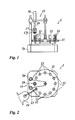
- Fig. 1 and 2 show a glass processing machine 1 for the production of glass moldings from molten glass gobs.
- a turntable 11 On a turntable 11, the one in the Fig. 1 and 2 not shown drive, are arranged on a pitch circle press molds 12 with the same pitch.
- 12 dies are arranged on the pitch circle so that the pitch is 30 °.
- the turntable 11 is consequently switchable in the transport cycle by 30 °.
- the turntable is rotated in the transport cycle by 30 ° clockwise.
- a feeder head 14 is arranged above a gutter system 13, whose outlet section is arranged in the working cycle over a press mold 12.
- a pressing station 15 is arranged above the turntable 11 and has an upper tool holder 16, on whose turntable 11 facing end portion of a ram 17 is arranged.
- a spring cage 17 f is arranged with a cover ring, which isteurgreifbar of the ram 17.
- the pressing station 15 is offset by a pitch spaced downstream of the gutter system 13.
- the pressing die 17 is in alignment with one of the dies 12.
- the tool holder 16 is rigidly connected to the rotor of a coaxial linear motor 18.
- the stator of the linear motor 18 is connected to the frame of the glass processing machine 1.
- a glass gob is formed in the feeder 14 and below the feeder outlet of a in the Fig. 1 and 2 scissors not shown cut off.
- This glass gob has the mass of glassware to be produced.
- the glass drop falls into the gutter system 13 and drops from the outlet of the gutter system 13 into an empty mold 12 provided in the feed position of the turntable 11.
- the transport cycle of the turntable 11 and now starts the glass gland filled mold 12 passes into the pressing position under the pressing station 15th
- the ram 17 moves down, and the glass gob is pressed until the cavity between the inner wall of the mold 12 and the outer wall of the ram 17 is filled with molten glass.
- the press die remains in this position until the glass mass has cooled sufficiently to remain dimensionally stable in order to ensure the further process steps until removal of the glass article,
- the cooled glass article is removed from the die 12 and usually fed to a fire polishing machine.
- press ridges are fused and the surface of the glass articles is optically improved by melting the edge layer.
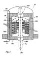
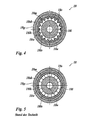
- Fig. 3 and 4 show the schematic structure of a cylinder-shaped linear motor 18th Fig. 3 shows a schematic cross section through the linear motor 18, Fig. 4 a schematic sectional view of the linear motor in Fig. 1 ,
- Fig. 3 shows in a schematic spatial representation of the structure of the linear motor 18.
- the cylinder-shaped linear motor 18 has an outer stator 18s and a run in the stator 18s linearly runner 181 on.
- the linear motor 18 has the following configuration from outside to inside: a stator core 18sk with coil teeth, a stator winding 18w arranged in the stator core 18sk, annularly arranged permanent magnets constituting one of a plurality of rotor magnets 18m, and a rotor core 181k on or in which the rotor magnets 18 m are arranged. Between the rotor 181 and the stator 18s, an air gap 181s is formed.
- the rotor core 181k is penetrated by a motor shaft 18a, which is mounted in two linear bearings 18al.
- the glass forming machine facing end portion of the motor shaft 18a is referred to as output 18ab.
- the linear motor 18 has a housing 18g in which the stator 18s and the linear bearings 18al are arranged.
- the housing 18g is penetrated by a cooling device 18k, which in Fig. 3 symbolically drawn.
- the housing is connected via the pressing station 15 rigidly connected to the frame of the glass forming machine.
- Fig. 3 shows in a sectional view perpendicular to the motor axis, wherein the section is laid through a stator winding 18w, that the stator windings 18w are formed wave-shaped.
- Fig. 5 shows a comparison formed by a prior art linear motor with annular air gap without elevations and depressions in the air gap surface.
- the rotor core 181k may be formed of soft magnetic solid material.
- the stator core 18sk is formed of stacked pole pieces of soft magnetic material.
- the stator core 18sk has recesses into which the stator windings 18w are inserted and which form coil teeth between adjacent stator windings 18w in the axial direction of the linear movement of the rotor 181, hereinafter referred to as the linear axial direction ( Fig. 3 ).
- the magnetic field lines formed between the current-carrying stator windings 18w and the rotor magnet 18m pass through the soft-magnetic material of the stator or rotor core and pass in the area of the air gap from the stator core into the rotor core and vice versa.
- the rotor magnets 18m are spaced apart in the linear axis direction (see Fig. 3 ).
- the distances of the rotor magnets 18m to each other are referred to as pole pitch.
- the coil teeth arranged between the stator windings 18w have a pole pitch, wherein the two pole pitches do not coincide.
- a traveling field described in more detail below generates the driving force. Simplified, it can be said that in operation, for example, two currently abutting opposing south poles, while a staggered north pole of the stator attracts the next south pole of the rotor.
- the radial air gap 18ls formed between the stator core 18s and the rotor core 18l should be as small as possible. Usual air gaps are between 0.8 and 1.5 mm. In this case - / + 0.1 mm air gap in relation to +/- 3% driving force, d. H. if the air gap 18l is reduced by 0.1 mm, the driving force increases by 3%.
- the rotor magnets 18m formed as permanent magnets are made of high energy product materials such as neodymium-iron-boron (NdFeB) or samarium-cobalt (SmCo). Rotor magnets 18m adjacent in the linear axis direction have opposite magnetic polarity.
- NdFeB neodymium-iron-boron
- SmCo samarium-cobalt
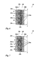
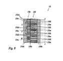
- the Fig. 6 to 8 show in schematic representations three basic versions of coaxial linear motors.
- stator windings 18w are designed for three-phase current (U, V, W) and, when energized, generate the traveling magnetic field which carries along the rotor magnets 18m arranged one above the other in the linear axis direction.
- Fig. 6 shows an embodiment of the linear motor 18, in which the rotor magnets 18m are radially polarized. Successive rotor magnets 18m have a different polarity, that is, N, S, N, etc. The rotor magnets 18m are adhered to the rotor core 18lk.
- the stator core 18s has coil teeth, which are each surrounded by at least one stator winding 18w (U, V, W).
- stator laminations that form the stator core 18sk must also be radially aligned and designed to be comparable to pie wedges with a wedge-shaped cross-section.
- the rotor core 18lk may be formed as a solid magnetically conductive core.
- Fig. 7 shows a second embodiment of the linear motor 18, in which the rotor magnets 18m are radially polarized. Successive rotor magnets 18m have a different polarity, that is, N, S, N, etc. The rotor magnets 18m are adhered to the rotor core 18lk.
- the stator core 18sk is now formed from axially stacked Polschuhin same thickness, which are inserted into a cylindrical shell, so that there is a simple structure, With uneven thickness, a reduction of the latching forces of the linear motor 18 may result.
- the stator windings 18w are disposed between the pole piece discs.
- Fig. 8 shows a third embodiment of the linear motor 18, in which the rotor magnets 18m are axially polarized.
- the rotor magnets 18m are inserted in the rotor core 18lk, with annular pole pieces arranged in stack between the rotor magnets 18m, whereby the core structure of the rotor 18l is analogous to that of the stator 18s.
- This Structure may be preferred, wherein the rotor magnets 18m may be formed of similar segments, which are arranged close to a ring, as described above Fig. 4 shown.
- stator core 18sk and the rotor core 18lk very high attraction forces occur, which can lead to deformations of the rotor and / or stator in linear motors with non-coaxial construction, especially in continuous operation, so that the stator and rotor come into contact, with high wear can occur. Due to the coaxial construction of the linear motor 18, an almost complete force compensation occurs, so that the high attractive forces between stator core 18s and rotor core 18lk cause comparatively small deformations and load the rotor bearings far less.
- the active area is characterized by the product of the circumferential length of the rotor core and the active height extending along the linear axis.
- the active rotor surface is the rotor surface, which actively contributes to the rotor movement and over which the forces between the stator and rotor are transmitted. From the transmitted force and the active rotor surface, the surface load occurring in the active rotor surface can be determined.
- Stator surface is initially a potentially active surface, because due to the linear movement of the rotor relative to the stator is always active only the proportion of the active stator, which corresponds to the active rotor surface.
- the active stator surface is therefore larger than the active rotor surface, however, the surface load of the active stator is as high as the surface load of the active rotor surface, because only the active rotor surface corresponding portion of the active stator is charged.
- the active surface has elevations and depressions. The elevations and depressions fold up the active rotor surface or stator surface so that the circumferential length increases and the active area is increased for the same active height.
- the resulting active surface can be simplified by the attribute "wavy" described, the rotor 18l is formed in cross-section star-shaped, equally the inner contour of the stator 18s is formed in a star-shaped cross-section and consequently also the stator winding 18w is formed star-shaped. But it is also possible that the stator winding 18w is circular and only the inner contour of the stator 18s is star-shaped.
- a trained linear motor with an outer diameter of 200 mm and an active diameter of 140 mm has an active circumferential length of 762 mm.
- a trained according to the prior art linear motor of the same size with the same active diameter only an active circumferential length of 440 mm.
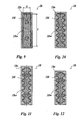
- Fig. 9 to 12 show embodiments of coaxial linear motors with rectangular rotor cross-section.
- Fig. 9 shows a first embodiment of a linear motor according to the invention with a rectangular rotor cross-section, which is used in the following as a comparative scale.
- a linear motor with a rotor width b already has an active area compared to a linear motor with a circular cross-section and a rotor diameter b, which is greater by at least 27% (with a square cross-section) than in the linear motor according to the prior art.
- the peak force of the linear motor in Fig. 9 F s 35 kN, the specific area force density in the air gap is 8 N / cm 2 .
- the rotor 18l has a rectangular cross-section and is guided in the rectangular interior of the stator 18s to form an air gap.
- the height of the active surface is 509 mm.
- Fig. 10 shows a second embodiment of a linear motor according to the invention with a rectangular rotor cross-section.
- the linear motor 18 has a cross-sectionally substantially rectangular rotor 18l, which has a wavy profile on both longitudinal sides, ie the surface of the rotor 18l is corrugated formed with bumps and depressions, whereby the active circumferential length relative to the circumferential length of in Fig. 9 shown linear motor is further increased.
- the circumferential length is in the in Fig. 10 shown Embodiment increased from 860 mm to 1400 mm, so that the active height is reduced to 313 mm with the same performance parameters and the relevant for the rigidity of the height of the stator 18s is lowered from 1009 mm to 813 mm.
- the end faces of the rectangular rotor cross-section are formed for design reasons not wavy and go with an outwardly arched arc section in the wavy longitudinal sides.
- Fig. 11 shows a third embodiment of a linear motor according to the invention with a rectangular rotor cross-section.
- the linear motor 18 in Fig. 11 is like the one in Fig. 10 described linear motor, with the difference that the active circumferential length is increased by extending the longitudinal sides of the rotor 18l to 1450 mm, and that the end sides of the rectangular rotor cross-section with an inwardly curved arc section in the corrugated longitudinal sides.
- the active height is now reduced to 302 mm with the same performance parameters and the height of the stator 18s, which is relevant for the rigidity, is reduced from 1009 mm to 802 mm.
- Fig. 12 shows a fourth embodiment of a linear motor according to the invention with a rectangular rotor cross-section.
- the linear motor 18 in Fig. 12 is like the one in Fig. 10 described linear motor, with the difference that the active circumferential length of 860 mm is increased to 1250 mm, although the longitudinal sides of the rotor 18l over the in Fig. 9 illustrated embodiment are shortened, and that the end faces of the rectangular rotor cross-section with an inwardly arched arc section in the wavy longitudinal sides.
- the active height is now shortened to 350 mm with the same performance parameters and the height of the stator 18s, which is relevant for the rigidity, is reduced from 1009 mm to 850 mm.
- the rotor magnets in the versions in FIGS. 11 and 12 can be composed of similar permanent magnets because of the special design of the rotor circumference, so that an equally simple structure is possible, as described above in Fig. 4 shown.
- the following table contains parameters of the Fig. 9 to 12 compared faced linear motors.
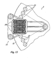
- Fig. 13 shows a second embodiment of the glass processing machine according to the invention.
- illustrated glass processing machine 1 is as in Fig. 1 and 2 illustrated glass processing machine, with the difference that instead of a linear motor, three linear motors are arranged side by side, so that three glass articles can be produced simultaneously in a work cycle.
- the linear motors 18 have a rectangular cross section, so that with the same power and height of the pitch of the shapes of a group can be reduced to each other, whereby a turntable smaller dimensions and thus smaller inertia is made possible with correspondingly higher dynamics and increased number of cycles.
- Each three adjacent glass molds 12 are arranged on the turntable in a line, so that the linear motors 18 form a compact unit.
Landscapes
- Engineering & Computer Science (AREA)
- Chemical & Material Sciences (AREA)
- Manufacturing & Machinery (AREA)
- Materials Engineering (AREA)
- Organic Chemistry (AREA)
- Power Engineering (AREA)
- Physics & Mathematics (AREA)
- Combustion & Propulsion (AREA)
- Electromagnetism (AREA)
- Mechanical Engineering (AREA)
- Linear Motors (AREA)
Abstract
Description
- Die Erfindung betrifft einen elektrischen Linearmotor.
- Linearmotore hoher Leistung werden zunehmend anstelle hydraulischer Antriebe in Glasformmaschinen zum Direktantrieb eines Pressstempels eingesetzt.
- Die
EP 1 330 417 B1 beschreibt eine Glasformmaschine mit einem Drehtisch, auf dem Glasformen kreisförmig angeordnet sind. Über dem Drehtisch ist ein elektrischer Linearmotor angeordnet, der einen Pressstempel direkt antreibt. Der für einen hinreichend leistungsfähigen elektrischen Linearmotor erforderliche Platzbedarf setzt jedoch dem Einsatz des Linearmotors hinsichtlich kurzer Taktzeiten und Mehrfachanordnungen des Linearmotors Grenzen. - Die
US 2006/0181157 A1 beschreibt ein lineares elektrodynamisches System für die Umwandlung mechanischer Bewegung in elektrische Energie oder umgekehrt. Der Stator dieses Systems weist mehrere ringförmig angeordnete elektrische Spulen auf, die mit sternförmig auf einer Achse angeordneten Magnetgruppen zusammenwirken. Es handelt sich also um mehrere parallel geschaltete Lineargeneratoren bzw. Linearmotore. - Aufgabe der vorliegenden Erfindung ist es, einen hinsichtlich der Leistungsfähigkeit und der Abmessungen verbesserten elektrischen Linearmotor anzugeben.
- Erfindungsgemäß wird diese Aufgabe mit dem Gegenstand des Anspruchs 1 gelöst.
- Es wird ein elektrischer Linearmotor mit einem Stator und einem Läufer vorgeschlagen, wobei der Stator elektrisch beaufschlagbare Statorwicklungen und eine unter Wirkung der Statorwicklungen aktive Statorfläche aufweist und der Läufer Permanentmagnete und eine von magnetischen Feldlinien durchgriffene aktive Läuferfläche aufweist, wobei der Läufer relativ zum Stator linear in eine bestimmte Linearrichtung geführt ist unter Ausbildung eines Luftspalts zwischen der aktiven Läuferfläche und der aktiven Statorfläche, wobei vorgesehen ist, dass die aktive Läuferfläche und/oder die aktive Statorfläche uneben und nicht konstant gekrümmt ausgebildet sind bzw. ist und mindestens eine sich entlang der Linearrichtung längs erstreckende Erhebung und/oder mindestens eine sich entlang der Linearrichtung längs erstreckende Vertiefung aufweisen bzw. aufweist.
- Die aktive Läuferfläche ist die Läuferfläche, die aktiv zur Läuferbewegung beiträgt und über die die Kräfte zwischen Stator und Läufer übertragen werden. Aus der übertragenen Kraft und der aktiven Läuferfläche kann die in der aktiven Läuferfläche auftretende Flächenbelastung bestimmt werden. Die aktive Statorfläche ist zunächst eine potentiell aktive Fläche, denn infolge der Linearbewegung des Läufers relativ zum Stator ist immer nur der Anteil der aktiven Statorfläche aktiv, der mit der aktiven Läuferfläche korrespondiert. Die aktive Statorfläche ist daher größer als die aktive Läuferfläche, jedoch ist die Flächenbelastung der aktiven Statorfläche so hoch wie die Flächenbelastung der aktiven Läuferfläche, weil immer nur der der aktiven Läuferfläche entsprechende Abschnitt der aktiven Statorfläche belastet ist.
- Die aktive Läuferfläche ist gebildet aus der Länge bzw. der Umfangslänge des Läuferkerns und der längs der Linearachse erstreckten aktiven Höhe. Die Erhöhungen und Vertiefungen falten die aktive Läuferfläche bzw. Statorfläche auf, so dass die Umfangslänge steigt und bei gleicher aktiver Höhe die aktive Fläche vergrößert ist. Die so entstandene aktive Fläche kann bei bevorzugten Ausführungen vereinfacht durch das Attribut "wellenförmig" beschrieben werden.
- Der erfindungsgemäße Linearmotor zeichnet sich dadurch aus, dass er wegen der vorzugsweise wellenförmig gefalteten aktiven Außenfläche des Läufers gegenüber Linearmotoren nach dem Stand der Technik bei gleicher Bauhöhe eine höhere Kraft entfaltet oder bei gleicher Kraftentfaltung eine geringere Bauhöhe aufweisen kann und/oder schmaler ausgebildet sein kann.
- Weiter kann der Linearmotor auch eine verringerte Masse und/oder eine geringere Schwingungsanfälligkeit aufweisen.
- Der erfindungsgemäße Linearmotor kann so beispielsweise mit einer höheren Taktfrequenz betrieben werden, so dass bei Einsatz beispielsweise in einer Glasformmaschine der Ausstoß an Glasformteilen erhöht werden kann.
- Ein weiterer Vorteil kann sein, dass mehrere der erfindungsgemäßen Linearmotore eng beieinander angeordnet sein können, weil sie bei gleich oder höherer Leistungsfähigkeit schmaler ausgebildet sein können, als Linearmotore nach dem Stand der Technik, so dass eine weitere Steigerung des Ausstoßes durch Parallelbearbeitung möglich ist.
- Der erfindungsgemäße Linearmotor kann auch an Drehtischen mit geringem Durchmesser eingesetzt werden, die gegenüber Drehtischen mit größerem Durchmesser mit einer höheren Taktfrequenz betreibbar sind, wodurch der Ausstoß an Glasartikeln erhöhbar ist.
- Es kann vorgesehen sein, dass die aktive Statorfläche und die aktive Läuferfläche im Querschnitt senkrecht zur Linearrichtung komplementär zueinander ausgebildet sind. Zwischen Innenwand des Stators und die Außenwand des Läufers kann so ein konstanter Luftspalt zwischen Stator und Läufer ausgebildet sein.
- Weiter kann vorgesehen sein, dass die Erhebungen und Vertiefungen in einem regelmäßigen Muster angeordnet sind.
- In einer weiteren Ausbildung kann vorgesehen sein, dass das Muster der Erhebungen und Vertiefungen symmetrisch zu einer längs zur Bewegungsrichtung angeordneten Längsebene ausgebildet ist.
- Weiter kann vorgesehen sein, dass die Erhebungen und/oder Vertiefungen im Querschnitt senkrecht zur linearen Bewegungsrichtung wellenförmig mit abgerundeten Wellenbergen und/oder Wellentälern oder mit plissierten Wellenbergen und/oder Wellentälern ausgebildet sind. Bei der plissierten Ausbildung handelt es sich um scharfkantige Erhebungen in der Art einer Plissee-Faltung, während die abgerundeten Ausführungen mit der Form von Wellblech vergleichbar sind.
- Es kann vorgesehen sein, dass der Läufer in einem Innenraum des Stators vom Stator umgeben oder an einer Außenseite des Stators den Stator umgebend linear geführt ist unter Ausbildung eines ringförmigen Luftspalts zwischen der aktiven Läuferfläche und der aktiven Statorfläche. Diese Bauform des Linearmotors kann auch als koaxialer Linearmotor bezeichnet werden. Koaxiale Linearmotoren haben den Vorteil, dass die Anziehungskräfte zwischen Stator und Läufer weitgehend kompensierbar sind, so dass die Lagerbelastung sinkt und weiter geringere Anforderungen an die Steifigkeit der Motorkonstruktion gestellt werden.
- Es kann vorgesehen sein, dass die aktiven Läuferfläche und/oder aktiven Statoriläche einen senkrecht zur linearen Bewegungsrichtung ausgebildeten Querschnitt mit im wesentlichen runder Grundkonfiguration aufweist, wobei die Kontur des Querschnitts zumindest abschnittsweise wellenförmig ist.
- Es kann insbesondere vorgesehen sein, dass die Grundkonfiguration des Querschnitts kreisrund ist.
- Es kann aber auch vorgesehen sein, dass die Grundkonfguration des Querschnitts elliptisch ist.
- Es ist auch möglich, dass die Grundkonfiguration des Querschnitts ein regelmäßiges Vieleck ist. Es kann sich beispielsweise um ein Quadrat oder Rechteck handeln, wobei durch die Wahl einer rechteckförmigen Grundkonfiguration schmale Linearmotore ausbildbar sind, die sich gut in einer Reihe nebeneinander anordnen lassen.
- In einer weiteren Ausbildung kann vorgesehen sein, dass der Läufer einen rechteckförmigen Querschnitt aufweist, dessen Außenkontur abschnittsweise ein wellenförmiges Profil aufweist, Beispielsweise kann vorgesehen sein, nur die Längsseiten des rechteckförmigen Querschnitts mit einem Profil auszubilden. Bevorzugt können für gegenüberliegende Abschnitte des Querschnitts spiegelbildliche Profile sein.
- Weiter kann vorgesehen sein, dass der Läufer in einem Innenraum des Stators vom Stator umgeben oder an einer Außenseite des Stators den Stator umgebend linear geführt ist unter Ausbildung eines ringförmigen Luftspalts zwischen der aktiven Läuferfläche und der aktiven Statorfläche und dass die aktive Läuferfläche und/oder die aktive Rotorfläche im Querschnitt senkrecht zur Linearrichtung ringförmig, aber nicht kreisringförmig ausgebildet sind bzw. ist, wobei der ringförmige Querschnitt die Kontur eines regelmäßigen oder unregelmäßigen Vielecks aufweist, dessen mindestens eine Ecke die mindestens eine Erhebung bildet oder der ringförmige, nicht kreisringförmige Querschnitt die Kontur einer Rundfläche mit über den Verlauf der Kontur variierten Krümmungsradius aufweist dessen mindestens ein Krümmungsmaximum mit minimalen Krümmungsradius die mindestens eine Erhebung bildet und/oder dessen mindestens ein Krümmungsminimum mit maximalen Krümmungsradius die mindestens eine Vertiefung bildet.
- Das Vieleck kann als Quadrat oder längliches Rechteck ausgebildet sein.
- Es kann auch vorgesehen sein, dass die Kontur der Rundfläche elliptisch oder eiförmig ausgebildet ist.
- Weiter kann vorgesehen sein, dass der Linearmotor folgende Leistüngsdaten aufweist: Nennkraft: 5 bis 20kN und/oder Spitzenkraft: 10 bis 40 kN und/oder Hub: 100 bis 1000 mm und/oder Geschwindigkeit: 0,1 bis 5 m/s.
- Der erfindungsgemäße Linearmotor kann für den Einsatz in einer Glasverarbeitungsmaschine vorgesehen sein, wobei der elektrische Linearmotor einen Pressenstempel und/oder einen Dosierplunger antreibt.
- Es kann vorgesehen sein, dass die Glasverarbeitungsmaschine einen Drehtisch mit Glasformen aufweist.
- Weiter kann der Drehtisch einen Schrittantrieb aufweisen, der es ermöglicht, die Glasformen taktweise zu bewegen.
- Es kann vorgesehen sein, dass die Glasformen mit konstantem Teilungsabstand kreisförmig auf dem Drehtisch angeordnet sind, wobei der Mittelpunkt des Teilkreises auf der Drehachse des Drehtisches liegt.
- Weiter kann vorgesehen sein, dass die Glasformen in Gruppen angeordnet sind und die Gruppen mit konstantem Teilungsabstand kreisförmig auf dem Drehtisch angeordnet sind, wobei der Mittelpunkt des Teilkreises auf der Drehachse des Drehtisches liegt. Es können beispielsweise drei Glasformen pro Gruppe vorgesehen sein, so dass gleichzeitig drei Glasformteile herstellbar sind, wobei für jede der Glasformen der Gruppe mindestens ein Linearmotor mit Pressstempel vorgesehen sein kann. Alternativ kann ein Linearmotor vorgesehen sein, der drei Pressstempel antreibt.
- Es kann vorgesehen sein, dass die Glasformen einer Gruppe auf einer Geraden angeordnet sind, wobei die Gerade eine Tangente oder Sekante an den Teilkreis bildet.
- Es kann weiter vorgesehen sein, dass der Drehtisch in eine Arbeitsphase schaltbar ist, in der der Drehtisch eine Position einnimmt, in der der mindestens eine Linearmotor über einer Glasform angeordnet ist, und dass der Drehtisch in eine Transportphase schaltbar ist, in der ein Schrittantrieb den Drehtisch um den Teilungsabstand dreht.
- In einer weiteren vorteilhaften Ausbildung kann vorgesehen sein, dass mehrere Linearmotore nebeneinander angeordnet sind, wie weiter oben ausgeführt.
- Es kann vorgesehen sein, dass die Linearmotore Läufer mit einem im Wesentlichen rechteckförmigen Querschnitt aufweisen.
- Weiter kann vorgesehen sein, dass die Linearmotore mit ihren Schmalseiten nebeneinander angeordnet sind.
- In einer weiteren bevorzugten Ausführung können die Linearmotore fluchtend nebeneinander angeordnet sein.
- Die Erfindung wird nun anhand von Ausführungsbeispielen näher erläutert. Es zeigen
- Fig. 1
- ein erstes Ausführungsbeispiel der erfindungsgemäßen Glasverarbeitungsmaschine mit einem koaxialen Linearmotor in einer schematischen Vorderansicht;
- Fig. 2
- die Glasverarbeitungsmaschine in
Fig. 1 in einer schematischen Draufsicht; - Fig. 3
- einen schematischen Querschnitt des Linearmotors in
Fig. 1 ; - Fig. 4
- eine schematische Schnittdarstellung des Linearmotors in
Fig. 1 ; - Fig. 5
- eine schematische Schnittdarstellung eines koaxialen Linearmotors nach dem Stand der Technik;
- Fig. 6
- eine erste Prinzipdarstellung zur Veranschaulichung des Magnetflussverlaufs in dem koaxialen Linearmotor;
- Fig. 7
- eine zweite Prinzipdarstellung zur Veranschaulichung des Magnetflussverlaufs in dem koaxialen Linearmotor;
- Fig. 8
- eine dritte Prinzipdarstellung zur Veranschaulichung des Magneiflussverlaufs in dem koaxialen Linearmotor;
- Fig. 9
- ein erstes Ausführungsbeispiel eines erfindungsgemäßen koaxialen Linearmotors mit länglichem Querschnitt in einer schematischen Schnittdarstellung;
- Fig. 10
- ein zweites Ausführungsbeispiel eines erfindungsgemäßen koaxialen Linearmotors mit länglichem Querschnitt in einer schematischen Schnittdarstellung;
- Fig. 11
- ein drittes Ausführungsbeispiel eines erfindungsgemäßen koaxialen Linearmotors mit länglichem Querschnitt in einer schematischen Schnittdarstellung;
- Fig. 12
- ein viertes Ausführungsbeispiel eines erfindungsgemäßen koaxialen Linearmotors mit länglichem Querschnitt in einer schematischen Schnittdarstellung;
- Fig. 13
- ein zweites Ausführungsbeispiel der erfindungsgemäßen Glasverarbeitungsmaschine in einer schematischen Draufsicht (Teilansicht).
-
Fig. 1 und 2 zeigen eine Glasverarbeitungsmaschine 1 zur Herstellung von Glasformkörpern aus geschmolzenen Glastropfen. - Auf einem Drehtisch 11, der einen in den
Fig. 1 und 2 nicht dargestellten Antrieb aufweist, sind auf einem Teilkreis Pressformen 12 mit gleichem Teilungsabstand angeordnet. In dem inFig. 1 und 2 dargestellten Ausführungsbeispiel sind 12 Pressformen auf dem Teilkreis angeordnet, so dass der Teilungsabstand 30° ist. Der Drehtisch 11 ist folglich im Transporttakt um 30° schaltbar. In dem Ausführungsbeispiel wird der Drehtisch im Transporttakt um 30° im Uhrzeigersinn gedreht. - Ein Speiserkopf 14 ist über einem Rinnensystem 13 angeordnet, dessen Austrittsabschnitt im Arbeitstakt über einer Pressform 12 angeordnet ist.
- Eine Pressstation 15 ist über dem Drehtisch 11 angeordnet und weist eine obere Werkzeugaufnahme 16 auf, an deren dem Drehtisch 11 zugewandten Endabschnitt ein Pressstempel 17 angeordnet ist. An der Werkzeugaufnahme 16 ist ein Federkorb 17f mit einem Deckring angeordnet, der von dem Pressstempel 17 durchgreifbar ist. Wenn der Pressstempel 17 in die Pressform abgesenkt ist, verschließt der Deckring die Pressform und formt den Oberrand des in der Pressform geformten Glasformkörpers aus. Die Pressstation 15 ist um einen Teilungsabstand versetzt stromabwärts hinter dem Rinnensystem 13 angeordnet. Der Pressstempel 17 fluchtet im Arbeitstakt mit einer der Pressformen 12. Die Werkzeugaufnahme 16 ist mit dem Läufer eines koaxialen Linearmotors 18 starr verbunden, Der Stator des Linearmotors 18 ist mit dem Gestell der Glasverarbeitungsmaschine 1 verbunden.
- Im Arbeitsablauf der Glasverarbeitungsmaschine wird im Speiser 14 ein Glastropfen gebildet und unterhalb des Speiserauslasses von einer in den
Fig. 1 und 2 nicht dargestellten Schere abgeschnitten. Dieser Glastropfen hat die Masse des zu produzierenden Glasartikel. Nach dem Scherenschnitt fällt der Glastropfen in das Rinnensystem 13 und fällt vom Auslass des Rinnensystems 13 in eine in der Speiseposition des Drehtisches 11 bereitgestellte leere Pressform 12. Sobald der Glastropfen in der Pressform 12 abgelegt ist, startet der Transporttakt des Drehtisches 11 und die nunmehr mit dem Glastropfen gefüllte Pressform 12 gelangt in die Pressposition unter der Pressstation 15. - Der Pressstempel 17 fährt nach unten, und der Glastropfen wird verpresst, bis die Kavität zwischen der Innenwand der Pressform 12 und der Außenwand des Pressstempels 17 mit schmelzflüssiger Glasmasse ausgefüllt ist. Der Pressstempel verweilt in dieser Lage solange, bis die Glasmasse genügend abgekühlt ist, um formstabil zu bleiben, um die weiteren Prozessschritte bis zur Entnahme des Glasartikels sicherzustellen,
- Nach dem Pressen findet auf den der Pressstation 15 folgenden Positionen bis zur Entnahme des Glasartikels im Wesentlichen die Glas- und Formenkühlung statt.
- Danach wird der gekühlte Glasartikel aus der Pressform 12 entnommen und in der Regel einer Feuerpoliermaschine zugeführt. Auf der Feuerpoliermaschine werden Pressgrate verschmolzen und wird die Oberfläche der Glasartikel durch Aufschmelzen der Randschicht optisch verbessert.
- Die
Fig. 3 und4 zeigen den schematischen Aufbau eines zylinderförmig aufgebauten Linearmotors 18.Fig. 3 zeigt einen schematischen Querschnitt durch den Linearmotor 18,Fig. 4 einen schematische Schnittdarstellung des Linearmotors inFig. 1 . -
Fig. 3 zeigt in einer schematischen räumlichen Darstellung den Aufbau des Linearmotors 18. Der zylinderförmig aufgebaute Linearmotor 18 weist einen außen liegenden Stator 18s und einem in dem Stator 18s linear geführten Läufer 181 auf. Der Linearmotor 18 weist von außen nach innen folgenden Aufbau auf: einen Statorkern 18sk mit Spulenzähnen, eine in dem Statorkern 18sk angeordnete Statorwicklung 18w, ringförmig angeordnete Permanentmagnete, die einen von mehren Läufermagneten 18m bilden, und einen Läuferkem 181k, auf oder in dem die Läufermagnete 18 m angeordnet sind. Zwischen dem Läufer 181 und dem Stator 18s ist ein Luftspalt 181s ausgebildet. Der Läuferkem 181k ist von einer Motorachse 18a durchgriffen, die in zwei Linearlagern 18al gelagert ist. Der der Glasformmaschine zugewandte Endabschnitt der Motorachse 18a ist als Abtrieb 18ab bezeichnet. Der Linearmotor 18 weist ein Gehäuse 18g auf, in dem der Stator 18s sowie die Linearlager 18al angeordnet sind. Das Gehäuse 18g ist von einer Kühleinrichtung 18k durchgriffen, die inFig. 3 symbolisch eingezeichnet ist. Das Gehäuse ist über die Pressstation 15 starr mit dem Gestell der Glasformmaschine verbunden. - Wie in
Fig. 3 zu erkennen, sind der Läufer 181 und der Stator 18s an ihrem Außenumfang bzw. Innenumfang wellenförmig ausgebildet, so dass der jeweilige Umfang größer ist als bei kreisförmiger Ausbildung.Fig. 4 zeigt in einer Schnittdarstellung senkrecht zur Motorachse, wobei der Schnitt durch eine Statorwicklung 18w gelegt ist, dass auch die Statorwicklungen 18w wellenförmig ausgebildet sind.Fig. 5 zeigt im Vergleich einen nach dem Stand der Technik ausgebildeten Linearmotor mit kreisringförmigem Luftspalt ohne Erhebungen und Vertiefungen in der Luftspalttläche. - Der Läuferkern 181k kann aus weichmagnetischem Vollmaterial ausgebildet sein. Der Statorkern 18sk ist aus aufeinander gestapelten Polschuhscheiben aus weichmagnetischem Material gebildet. Der Statorkern 18sk weist Aussparungen auf, in welche die Statorwicklungen 18w eingebracht sind und die in Achsrichtung der Linearbewegung des Läufers 181, im Weiteren Linearachsrichtung genannt, zwischen benachbarten Statorwicklungen 18w Spulenzähne ausbilden (
Fig. 3 ). Die zwischen den stromdurchflossenen Statorwicklungen 18w und den Läufermagneten 18m ausgebildeten magnetischen Feldlinien verlaufen durch das weichmagnetische Material des Stator- bzw. Läuferkerns und treten im Bereich des Luftspalts vom Statorkern in den Läuferkem über und umgekehrt. - Die Läufermagnete 18m sind in Linearachsrichtung voneinander beabstandet angeordnet (siehe
Fig. 3 ). Die Abstände der Läufermagnete 18m zueinander werden als Polteilung bezeichnet. Analog dazu weisen die zwischen den Statorwicklungen 18w angeordneten Spulenzähne eine Polteilung auf, wobei die beiden Polteilungen nicht übereinstimmen. Mit diesem Teilungsunterschied erzeugt ein weiter unten näher beschriebenes Wanderfeld die Antriebskraft. Vereinfacht kann gesagt werden, dass sich im Betrieb beispielsweise zwei momentan gegenüberstehende Südpole abstoßen, während ein versetzter Nordpol des Stators den nächst folgenden Südpol des Läufers anzieht. - Der zwischen dem Statorkern 18s und dem Läuferkern 18l ausgebildete radiale Luftspalt 18ls sollte so klein wie möglich sein. Übliche Luftspalte betragen zwischen 0,8 und 1,5 mm. Dabei stehen -/+ 0,1 mm Luftspalt in Relation zu +/-3% Antriebskraft, d. h. bei Verringerung des Luftspalts 18ls um 0,1 mm steigt die Antriebskraft um 3 %.
- Die als Permanentmagnete ausgebildeten Läufermagnete 18m sind aus Materialien mit hohem Energieprodukt, wie beispielsweise aus Neodym-Eisen-Bor (NdFeB) oder Samarium-Cobalt (SmCo) hergestellt. In Linearachsrichtung benachbarte Läufermagnete 18m weisen eine entgegengesetzte magnetische Polarität auf.
- Die
Fig. 6 bis 8 zeigen in schematischen Darstellungen drei prinzipielle Ausführungen koaxialer Linearmotore. - In allen drei Beispielen sind die Statorwicklungen 18w für Dreiphasenstrom ausgelegt (U, V, W) und erzeugen im bestromten Zustand das magnetische Wanderfeld, das die in Linearachsrichtung übereinander angeordneten Läufermagnete 18m mitnimmt.
-
Fig. 6 zeigt ein Ausführungsbeispiel des Linearmotors 18, bei dem die Läufermagnete 18m radial polarisiert sind. Aufeinanderfolgende Läufermagnete 18m weisen eine unterschiedliche Polarität auf, also N, S, N usw. Die Läufermagnete 18m sind auf den Läuferkem 18lk aufgeklebt. - Der Statorkern 18s weist Spulenzähne auf, die von jeweils mindestens einer Statorwicklung 18w umschlossen sind (U, V, W).
- In
Fig. 6 eingezeichnete Feldlinien verdeutlichen den magnetischen Fluss, der außerhaib der Magnete und Wicklungen durch magnetisch leitfähiges Material läuft und in sich geschlossene Feldlinien aufweist. Die Statorbleche, die den Statorkern 18sk bilden, müssen folglich auch radial ausgerichtet sein und vergleichbar mit Tortenstücken mit keilförmigem Querschnitt ausgebildet sein. Eine solche Anordnung hat jedoch den Nachteil, dass der Aufwand zur Herstellung und Schichtung der Statorbleche vergleichsweise hoch ist. Der Läuferkern 18lk kann als massiver magnetisch leitender Kern ausgebildet sein. -
Fig. 7 zeigt ein zweites Ausführungsbeispiel des Linearmotors 18, bei dem die Läufermagnete 18m radial polarisiert sind. Aufeinanderfolgende Läufermagnete 18m weisen eine unterschiedliche Polarität auf, also N, S, N usw. Die Läufermagnete 18m sind auf den Läuferkem 18lk aufgeklebt. - Der Statorkern 18sk ist nun aus axial aufeinandergeschichteten Polschuhscheiben gleicher Dicke gebildet, die in einen zylinderförmigen Mantel eingelegt sind, so dass sich ein einfacher Aufbau ergibt, Bei ungleichmäßiger Dicke kann sich eine Reduzierung der Rastkräfte des Linearmotors 18 ergeben. Die Statorwicklungen 18w sind zwischen den Polschuhscheiben angeordnet.
-
Fig. 8 zeigt ein drittes Ausführungsbeispiel des Linearmotors 18, bei dem die Läufermagnete 18m axial polarisiert sind. Die Läufermagnete 18m sind in den Läuferkem 18lk eingelegt, wobei zwischen den Läufermagneten 18m zu Stapeln angeordnete ringförmige Polschuhscheiben eingelegt sind, wodurch der Kernaufbau des Läufers 18l analog zu dem des Stators 18s ist. Dieser Aufbau kann bevorzugt sein, wobei die Läufermagnete 18m aus gleichartigen Segmenten ausgebildet sein können, die dicht an dicht zu einem Ring angeordnet sind, wie weiter oben inFig. 4 gezeigt. - Zwischen dem Statorkern 18sk und dem Läuferkern 18lk treten sehr hohe Anziehungskräfte auf, die bei Linearmotoren mit nichtkoaxialem Aufbau insbesondere im Dauerbetrieb zu Verformungen des Läufers und/oder Stators führen können, so dass Stator und Läufer zur Berührung kommen, wobei hoher Verschleiß eintreten kann. Durch den koaxialen Aufbau des Linearmotors 18 tritt eine fast vollständige Kraftkompensation ein, so dass die hohen Anziehungskräfte zwischen Statorkern 18sk und Läuferkern 18lk vergleichsweise kleine Verformungen hervorrufen und die Läuferlager weit weniger belasten.
- Für die Leistungsfähigkeit des Linearmotors entscheidend ist ein minimaler Luftspalt und eine maximale aktive Fläche, in der die Kraftübertragung realisiert ist. Die aktive Fläche wird charakterisiert durch das Produkt aus der Umfangslänge des Läuferkerns und der längs der Linearachse erstrecken aktiven Höhe. Für einen zylinderförmigen Läufer nach dem Stand der Technik (
Fig. 5 ) gilt:
mit A = aktive Fläche, D = Durchmesser des Läuferkerns und h = aktive Höhe. Die aktive Läuferfläche ist die Läuferfläche, die aktiv zur Läuferbewegung beiträgt und über die die Kräfte zwischen Stator und Läufer übertragen werden. Aus der übertragenen Kraft und der aktiven Läuferfläche kann die in der aktiven Läuferfläche auftretende Flächenbelastung bestimmt werden. Die aktive - Statorfläche ist zunächst eine potentiell aktive Fläche, denn infolge der Linearbewegung des Läufers relativ zum Stator ist immer nur der Anteil der aktiven Statorfläche aktiv, der mit der aktiven Läuferfläche korrespondiert. Die aktive Statorfläche ist daher größer als die aktive Läuferfläche, jedoch ist die Flächenbelastung der aktiven Statorfläche so hoch wie die Flächenbelastung der aktiven Läuferfläche, weil immer nur der der aktiven Läuferfläche entsprechende Abschnitt der aktiven Statorfläche belastet ist.
- Demgegenüber weist der in
Fig. 3 und4 dargestellte erfindungsgemäße Linearmotor 18 eine gegenüber einem Linearmotor des Standes der Technik vergrößerte Umfangslänge auf, wodurch die aktive Fläche vergrößert ist. Die aktive Fläche weist Erhebungen und Vertiefungen auf. Die Erhöhungen und Vertiefungen falten die aktive Läuferfläche bzw. Statorfläche auf, so dass die Umfangslänge steigt und bei gleicher aktiver Höhe die aktive Fläche vergrößert ist. Die so entstandene aktive Fläche kann vereinfacht durch das Attribut "wellenförmig" beschrieben werden, Der Läufer 18l ist im Querschnitt sternförmig ausgebildet, gleichermaßen ist die Innenkontur des Stators 18s im Querschnitt sternförmig ausgebildet und folglich ist auch die Statorwicklung 18w sternförmig ausgebildet. Es ist aber auch möglich, dass die Statorwicklung 18w kreisförmig und nur die Innenkontur des Stators 18s sternförmig ausgebildet ist. - Ein nach
Fig. 3 ausgebildeter Linearmotor mit einem Außendurchmesser von 200 mm und einem aktiven Durchmesser von 140 mm weist eine aktive Umfangslänge von 762 mm auf. Demgegenüber weist ein nach dem Stand der Technik ausgebildeter Linearmotor gleicher Abmessung bei gleichem aktiven Durchmesser nur eine aktive Umfangslänge von 440 mm auf. Durch die Erfindung wird hier eine Steigerung der Motorkraft auf 760/440 = 172 %, d. h. um 72 % erreicht. - Die
Fig. 9 bis 12 zeigen Ausführungsbeispiele koaxialer Linearmotore mit rechteckförmigem Läuferquerschnitt. -
Fig. 9 zeigt ein erstes Ausführungsbeispiel eines erfindungsgemäßen Linearmotors mit rechteckförmigem Läuferquerschnitt, der im folgenden als Vergleichsmaßstab herangezogen wird. Ein derartiger Linearmotor mit einer Läuferbreite b weist gegenüber einem Linearmotor mit kreisförmigem Querschnitt und einem Läuferdurchmesser b bereits eine aktive Fläche auf, die mindestens um 27 % (bei quadratischem Querschnitt) größer ist als bei dem Linearmotor nach dem Stand der Technik. Die Spitzenkraft des Linearmotors inFig. 9 beträgt Fs = 35 kN, die spezielle Flächenkraftdichte im Luftspalt 8 N/cm2. Die erforderliche aktive Fläche beträgt somit A = 4 375 cm2. Der Läufer 18l weist einen rechteckigen Querschnitt auf und ist im rechteckförmigen Innenraum des Stators 18s unter Ausbildung eines Luftspalts geführt. Der Läufer 18l hat die Querschnittsabmessungen b x I = 70 x 360 mm, d. h. die aktive Umfangslänge des Läufers beträgt (2 x 70) + (2 x 360) mm = 860 mm. Die Höhe der aktiven Fläche beträgt 509 mm. -
Fig. 10 zeigt ein zweites Ausführungsbeispiel eines erfindungsgemäßen Linearmotors mit rechteckförmigem Läuferquerschnitt. - Der Linearmotor 18 weist einen im Querschnitt im Wesentlichen rechteckförmigen Läufer 18l auf, der an beiden Längsseiten ein wellenförmiges Profil aufweist, d. h. die Oberfläche des Läufers 18l ist wellblechartig mit Erhebungen und Vertiefungen ausgebildet, wodurch die aktive Umfangslänge gegenüber der Umfangslänge des in
Fig. 9 dargestellten Linearmotors weiter vergrößert ist. Die Umfangslänge ist in dem inFig. 10 dargestellten Ausführungsbeispiel von 860 mm auf 1400 mm vergrößert, so dass die aktive Höhe bei gleichen Leistungsparametern auf 313 mm verkürzt ist und die für die Steifigkeit relevante Höhe des Stators 18s von 1009 mm auf 813 mm gesenkt ist. - Die Stirnseiten des rechteckförmigen Läuferquerschnitts sind aus konstruktiven Gründen nicht gewellt ausgebildet und gehen mit einem nach außen gewölbten Bogenabschnitt in die gewellten Längsseiten über.
-
Fig. 11 zeigt ein drittes Ausführungsbeispiel eines erfindungsgemäßen Linearmotors mit rechteckförmigem Läuferquerschnitt. - Der Linearmotor 18 in
Fig. 11 ist wie der inFig. 10 beschriebene Linearmotor ausgebildet, mit dem Unterschied, dass die aktive Umfangslänge durch Verlängerung der Längsseiten des Läufers 18l auf 1450 mm vergrößert ist, und dass die Stirnseiten des rechteckförmigen Läuferquerschnitts mit einem nach innen gewölbten Bogenabschnitt in die gewellten Längsseiten übergehen. Die aktive Höhe ist nun bei gleichen Leistungsparametern auf 302 mm verkürzt und die für die Steifigkeit relevante Höhe des Stators 18s von 1009 mm auf 802 mm gesenkt. -
Fig. 12 zeigt ein viertes Ausführungsbeispiel eines erfindungsgemäßen Linearmotors mit rechteckförmigem Läuferquerschnitt. - Der Linearmotor 18 in
Fig. 12 ist wie der inFig. 10 beschriebene Linearmotor ausgebildet, mit dem Unterschied, dass die aktive Umfangslänge von 860 mm auf 1250 mm erhöht ist, obwohl die Längsseiten des Läufers 18l gegenüber dem inFig. 9 dargestellten Ausführung verkürzt sind, und dass die Stirnseiten des rechteckförmigen Läuferquerschnitts mit einem nach innen gewölbten Bogenabschnitt in die gewellten Längsseiten übergehen. Die aktive Höhe ist nun bei gleichen Leistungsparametern auf 350 mm verkürzt und die für die Steifigkeit relevante Höhe des Stators 18s von 1009 mm auf 850 mm gesenkt. - Die Läufermagnete in den Ausführungen in
Fig. 11 und 12 können wegen der speziellen Ausbildung des Läuferumfangs aus gleichartigen Permanentmagneten zusammengesetzt werden, so dass ein ebenso einfacher Aufbau möglich ist, wie weiter oben inFig. 4 dargestellt. - In der nachfolgenden Tabelle sind Parameter der in den
Fig. 9 bis 12 dargestellten Linearmotoren gegenübergestellt.Ausführungsbeispiel Fig. 7 Fig. 8 Fig. 9 Fig. 10 aktive Umfangslänge 860 mm 1400 mm 1450 mm 1250 mm aktive Höhe 509 mm 313 mm 302 mm 350 mm Läuferlänge 509 mm 313 mm 302 mm 350 mm aktiver Hub 500 mm 500 mm 500 mm 500 mm Länge I des Läuferquerschnitts 440 mm 440 mm 478 mm 416 mm Breite b des 150 mm 150 mm 150 mm 150 mm Läuferquerschnitts Höhe des Stators 1009 mm 813 mm 802 mm 850 mm relative aktive Umfangslänge 1,00 1,63 1,69 1,45 - Die gegenüber dem Vergleichsmotor kürzere Baulänge der Linearmotore in
Fig. 8 bis 10 erhöht die Steifigkeit des Linearmotors weiter und reduziert schädliche Schwingungen, so dass der Linearmotor mit höherer Taktzahl betreibbar ist, wodurch die Taktzeit des Drehtischs reduziert werden kann. -
Fig. 13 zeigt ein zweites Ausführungsbeispiel der erfindungsgemäßen Glasverarbeitungsmaschine. - Die in
Fig. 13 dargestellte Glasverarbeitungsmaschine 1 ist wie die inFig. 1 und 2 dargestellte Glasverarbeitungsmaschine aufgebaut, mit dem Unterschied, dass anstelle eines Linearmotors drei Linearmotore nebeneinander angeordnet vorgesehen sind, so dass in einem Arbeitstakt drei Glasartikel gleichzeitig herstellbar sind. - Die Linearmotore 18 weisen einen rechteckförmigen Querschnitt auf, so dass bei gleicher Leistung und Bauhöhe der Teilungsabstand der Formen einer Gruppe zueinander verringert werden kann, wodurch ein Drehtisch kleinerer Abmessungen und damit kleinerer Massenträgheit mit entsprechend höherer Dynamik und gesteigerter Taktzahl ermöglicht wird.
- Jeweils drei benachbarte Glasformen 12 sind auf dem Drehtisch in einer Linie angeordnet, so dass auch die Linearmotoren 18 eine kompakte Einheit bilden.
-
- 1
- Glasverarbeitungsmaschine
- 1 g
- Gestell
- 11
- Drehtisch
- 12
- Pressform
- 13
- Rinnensystem
- 14
- Speiserkopf
- 15
- Pressstation
- 16
- Werkzeugaufnahme
- 17
- Pressstempel
- 17f
- Federkorb
- 18
- koaxialer Linearmotor
- 18a
- Motorachse
- 18ab
- Abtrieb
- 18al
- Linearlager
- 18g
- Motorgehäuse
- 18k
- Kühleinrichtung
- 18l
- Läufer
- 18ls
- Luftspalt
- 18lk
- Läuferkern
- 18m
- Läufermagnet
- 18s
- Stator
- 18sk
- Statorkern
- 18w
- Statorwicklung
Claims (15)
- Elektrischer Linearmotor (18) mit einem Stator (18s) und einem Läufer (18l), wobei der Stator (18s) elektrisch beaufschlagbare Statorwicklungen (18w) und eine unter Wirkung der Statorwicklungen (18w) aktive Statortläche aufweist und der Läufer (18l) Permanentmagnete (18m) und eine von magnetischen Feldlinien durchgriffene aktive Läuferfläche aufweist, wobei der Läufer (18l) relativ zum Stator (18s) linear in eine bestimmte Linearrichtung geführt ist unter Ausbildung eines Luftspalts (18ls) zwischen der aktiven Läuferfläche und der aktiven Statorfläche,
dadurch gekennzeichnet,
dass die aktive Läuferfläche und/oder die aktive Statorfläche uneben und nicht konstant gekrümmt ausgebildet sind bzw. ist und mindestens eine sich entlang der Linearrichtung längs erstreckende Erhebung und/oder mindestens eine sich entlang der Linearrichtung längs erstreckende Vertiefung aufweisen bzw. aufweist, - Linearmotor nach Anspruch 1,
dadurch gekennzeichnet,
dass die aktive Statorfläche und die aktive Läuferfläche im Querschnitt senkrecht zur Linearrichtung komplementär zueinander ausgebildet sind. - Linearmotor nach einem der vorangehenden Ansprüche,
dadurch gekennzeichnet,
dass die aktive Läuferfläche und/oder die aktive Statorfläche mehrere Erhebungen und Vertiefungen in einem regelmäßigen Muster angeordnet aufweisen bzw. aufweist. - Linearmotor nach Anspruch 3,
dadurch gekennzeichnet,
dass das Muster der Erhebungen und Vertiefungen symmetrisch zu einer längs zur Bewegungsrichtung angeordneten Längsebene ausgebildet ist. - Linearmotor nach einem der vorangehenden Ansprüche,
dadurch gekennzeichnet,
dass die Erhebungen und/oder Vertiefungen im Querschnitt senkrecht zur linearen Bewegungsrichtung wellenförmig mit abgerundeten Wellenbergen und/oder Wellentälern oder mit plissierten Wellenbergen undloder Wellentälern ausgebildet sind. - Linearmotor nach einem der vorangehenden Ansprüche,
dadurch gekennzeichnet,
dass der Läufer (18l) in einem Innenraum des Stators (18s) vom Stator (18s) umgeben oder an einer Außenseite des Stators (18s) den Stator (18s) umgebend linear geführt ist unter Ausbildung eines ringförmigen Luftspalts zwischen der aktiven Läuferfläche und der aktiven Statorfläche. - Linearmotor nach Anspruch 6,
dadurch gekennzeichnet,
dass die aktive Läuferfläche und/oder aktive Statorfläche einen senkrecht zur linearen Bewegungsrichtung ausgebildeten Querschnitt mit im wesentlichen runder Grundkonfiguration aufweist, wobei die Kontur dieser Grundkonfiguration zumindest abschnittsweise wellenförmig ist. - Linearmotor nach einem der vorangehenden Ansprüche,
dadurch gekennzeichnet,
dass der Läufer (18l) in einem Innenraum des Stators (18s) vom Stator (18s) umgeben oder an einer Außenseite des Stators (18s) den Stator (18s) umgebend linear geführt ist unter Ausbildung eines ringförmigen Luftspalts zwischen der aktiven Läuferfläche und der aktiven Statortläche, und
dass die aktive Läuferfläche und/oder die aktive Rotorfläche im Querschnitt senkrecht zur Linearrichtung ringförmig, aber nicht kreisringförmig ausgebildet sind bzw. ist,
wobei der ringförmige Querschnitt die Kontur eines regelmäßigen oder unregelmäßigen Vielecks aufweist, dessen mindestens eine Ecke die mindestens eine Erhebung bildet'oder der ringförmige, nicht kreisringförmige Querschnitt die Kontur einer Rundfläche mit über den Verlauf der Kontur variierten Krümmungsradius aufweist dessen mindestens ein Krümmungsmaximum mit minimalen Krümmungsradius die mindestens eine Erhebung bildet und/oder dessen mindestens ein Krümmungsminimum mit maximalen Krümmungsradius die mindestens eine Vertiefung bildet. - Glasverarbeitungsmaschine mit mindestens einem elektrischen Linearmotor, der nach einem der vorangehenden Ansprüche ausgebildet ist,
dadurch gekennzeichnet,
dass der elektrische Linearmotor einen Pressenstempel und/oder einen Dosierplunger antreibt. - Glasverarbeitungsmaschine nach Anspruch 9
dadurch gekennzeichnet,
dass die Glasverarbeitungsmaschine einen Drehtisch (11) mit mehreren umfangsseitig angeordneten Glasformen (12) aufweist. - Glasverarbeitungsmaschine nach Anspruch 9 oder 10,
dadurch gekennzeichnet,
dass der Drehtisch (11) in eine Arbeitsphase schaltbar ist, in der der Drehtisch eine Position einnimmt, in der der mindestens eine Linearmotor (18) über einer Glasform (12) angeordnet ist, und dass der Drehtisch in eine Transportphase schaltbar ist, in der ein Schrittantrieb den Drehtisch (11) um den Teilungsabstand dreht. - Glasverarbeitungsmaschine nach einem der Ansprüche 9 bis 11,
dadurch gekennzeichnet,
dass mehrere Linearmotore (18) nebeneinander angeordnet sind. - Glasverarbeitungsmaschine nach Anspruch 12,
dadurch gekennzeichnet,
dass die Linearmotore (18) Läufer (18l) mit einem im Wesentlichen
rechteckförmigen Querschnitt aufweisen. - Glasverarbeitungsmaschine nach Anspruch 13,
dadurch gekennzeichnet,
dass die Linearmotore (18) mit ihren Schmalseiten nebeneinander angeordnet sind. - Glasverarbeitungsmaschine nach einem der Ansprüche 12 bis 14,
dadurch gekennzeichnet,
dass die Linearmotore (18) fluchtend nebeneinander angeordnet sind.
Priority Applications (1)
| Application Number | Priority Date | Filing Date | Title |
|---|---|---|---|
| EP10001197A EP2355314A1 (de) | 2010-02-05 | 2010-02-05 | Elektrischer Linearmotor |
Applications Claiming Priority (1)
| Application Number | Priority Date | Filing Date | Title |
|---|---|---|---|
| EP10001197A EP2355314A1 (de) | 2010-02-05 | 2010-02-05 | Elektrischer Linearmotor |
Publications (1)
| Publication Number | Publication Date |
|---|---|
| EP2355314A1 true EP2355314A1 (de) | 2011-08-10 |
Family
ID=42028162
Family Applications (1)
| Application Number | Title | Priority Date | Filing Date |
|---|---|---|---|
| EP10001197A Withdrawn EP2355314A1 (de) | 2010-02-05 | 2010-02-05 | Elektrischer Linearmotor |
Country Status (1)
| Country | Link |
|---|---|
| EP (1) | EP2355314A1 (de) |
Citations (8)
| Publication number | Priority date | Publication date | Assignee | Title |
|---|---|---|---|---|
| DE19811073A1 (de) * | 1998-03-13 | 1999-09-16 | Blum Gmbh | Zylindrischer, mehrphasiger Transversalflußaktor |
| DE10055080A1 (de) * | 2000-11-07 | 2002-05-16 | Bosch Gmbh Robert | Elektrische Linearmaschine |
| DE10156298A1 (de) * | 2000-11-20 | 2002-08-01 | Lg Electronics Inc | Kolbenmotor |
| US20020144519A1 (en) * | 2001-03-23 | 2002-10-10 | Gianclaudio Borsarelli | Punch assembly for producing hollow glass articles in a mold |
| US6701748B1 (en) * | 2000-10-06 | 2004-03-09 | Libbey Glass Inc. | Glassware machine |
| EP1596402A2 (de) * | 2004-03-26 | 2005-11-16 | Bose Corporation | Elektromagnetischer Aktor und zugehörige Steuerung |
| US20060181157A1 (en) | 2005-02-11 | 2006-08-17 | Infinia Corporation | Linear electrodynamic system and method |
| JP2006248869A (ja) * | 2005-03-14 | 2006-09-21 | Hoya Corp | モールドプレス成形装置、そのプレスヘッド、および光学素子の製造方法 |
-
2010
- 2010-02-05 EP EP10001197A patent/EP2355314A1/de not_active Withdrawn
Patent Citations (10)
| Publication number | Priority date | Publication date | Assignee | Title |
|---|---|---|---|---|
| DE19811073A1 (de) * | 1998-03-13 | 1999-09-16 | Blum Gmbh | Zylindrischer, mehrphasiger Transversalflußaktor |
| US6701748B1 (en) * | 2000-10-06 | 2004-03-09 | Libbey Glass Inc. | Glassware machine |
| EP1330417B1 (de) | 2000-10-06 | 2008-07-23 | LIBBEY GLASS Inc. | Maschine zur herstellung von glaswaren |
| DE10055080A1 (de) * | 2000-11-07 | 2002-05-16 | Bosch Gmbh Robert | Elektrische Linearmaschine |
| DE10156298A1 (de) * | 2000-11-20 | 2002-08-01 | Lg Electronics Inc | Kolbenmotor |
| US20020144519A1 (en) * | 2001-03-23 | 2002-10-10 | Gianclaudio Borsarelli | Punch assembly for producing hollow glass articles in a mold |
| EP1596402A2 (de) * | 2004-03-26 | 2005-11-16 | Bose Corporation | Elektromagnetischer Aktor und zugehörige Steuerung |
| US20060181157A1 (en) | 2005-02-11 | 2006-08-17 | Infinia Corporation | Linear electrodynamic system and method |
| US20080018179A1 (en) * | 2005-02-11 | 2008-01-24 | Infinia Corporation | Linear electrodynamic system and method |
| JP2006248869A (ja) * | 2005-03-14 | 2006-09-21 | Hoya Corp | モールドプレス成形装置、そのプレスヘッド、および光学素子の製造方法 |
Similar Documents
| Publication | Publication Date | Title |
|---|---|---|
| DE60211805T2 (de) | Statorkern für ein Magnetlager und Verfahren zu seiner Herstellung | |
| EP2951909B1 (de) | Rotor, reluktanzmaschine und herstellungsverfahren für den rotor | |
| DE112007000201T5 (de) | Geschlitzte Kerne für einen Motorstator, Motorstator, Synchronmotor des Permanentmagnetentyps, und Stanzverfahren durch Stanzstempel für geschlitzte Kerne | |
| DE102007002782A1 (de) | Drehantrieb mit geraden Primärteilsegmenten | |
| EP2831978B1 (de) | Vibrationsverhinderung bei synchronmaschinen | |
| EP2157328B1 (de) | Lagerungsanordnung für einen Maschinentisch mit magnetischer Entlastung | |
| WO2000001059A1 (de) | Synchronlinearmotor | |
| EP2963774B1 (de) | Mehrpoliges Bauteil für eine elektrische Maschine | |
| EP1858142A1 (de) | Linearmotor | |
| WO2016020120A2 (de) | Blech- oder sinterteil für einen stator oder einen läufer einer elektrischen maschine sowie verfahren zu dessen herstellung | |
| DE102012100332A1 (de) | Stator für eine rotierende elektrische Maschine und Verfahren zu seiner Herstellung | |
| EP2432722B1 (de) | Changiereinrichtung | |
| EP2523321A1 (de) | Zylindrischer Linearmotor mit geblechtem Ständer | |
| EP3934067A1 (de) | Wicklungssystem für eine elektrische maschine | |
| EP2122025B1 (de) | Galette | |
| EP3284157B1 (de) | Windenergieanlage und polpaket für einen synchrongenerator einer windenergieanlage sowie synchrongenerator | |
| EP3043456A1 (de) | Verfahren zur Herstellung eines Stator- oder Rotorelements für eine elektrische Maschine | |
| EP2355314A1 (de) | Elektrischer Linearmotor | |
| DE102019107136A1 (de) | Klauenpol-Stator für eine Transversalflussmaschine | |
| DE10150520B4 (de) | Elektrische Maschine | |
| EP3841659B1 (de) | Kompakte fertigungsstation zum zusammenfügen eines stators für einen elektromotor aus statorsegmenten | |
| EP2337195A2 (de) | Linearantrieb mit verbesserter Wirbelstromunterdrückung | |
| AT509183B1 (de) | Elektrischer motor mit rollendem läufer | |
| EP3679641B1 (de) | Rotierende elektrische maschine | |
| EP3054562A1 (de) | Elektrische Antriebsmaschine |
Legal Events
| Date | Code | Title | Description |
|---|---|---|---|
| PUAI | Public reference made under article 153(3) epc to a published international application that has entered the european phase |
Free format text: ORIGINAL CODE: 0009012 |
|
| AK | Designated contracting states |
Kind code of ref document: A1 Designated state(s): AT BE BG CH CY CZ DE DK EE ES FI FR GB GR HR HU IE IS IT LI LT LU LV MC MK MT NL NO PL PT RO SE SI SK SM TR |
|
| AX | Request for extension of the european patent |
Extension state: AL BA RS |
|
| 17P | Request for examination filed |
Effective date: 20120206 |
|
| 17Q | First examination report despatched |
Effective date: 20150825 |
|
| RIC1 | Information provided on ipc code assigned before grant |
Ipc: C03B 11/16 20060101ALI20170111BHEP Ipc: C03B 11/02 20060101ALI20170111BHEP Ipc: H02K 9/19 20060101ALN20170111BHEP Ipc: H02K 1/06 20060101ALN20170111BHEP Ipc: H02K 41/03 20060101AFI20170111BHEP Ipc: C03B 11/06 20060101ALI20170111BHEP Ipc: C03B 9/41 20060101ALI20170111BHEP Ipc: C03B 9/193 20060101ALI20170111BHEP Ipc: C03B 11/00 20060101ALI20170111BHEP |
|
| GRAP | Despatch of communication of intention to grant a patent |
Free format text: ORIGINAL CODE: EPIDOSNIGR1 |
|
| GRAJ | Information related to disapproval of communication of intention to grant by the applicant or resumption of examination proceedings by the epo deleted |
Free format text: ORIGINAL CODE: EPIDOSDIGR1 |
|
| INTG | Intention to grant announced |
Effective date: 20170223 |
|
| GRAP | Despatch of communication of intention to grant a patent |
Free format text: ORIGINAL CODE: EPIDOSNIGR1 |
|
| INTC | Intention to grant announced (deleted) | ||
| RIC1 | Information provided on ipc code assigned before grant |
Ipc: C03B 11/02 20060101ALI20170320BHEP Ipc: H02K 9/19 20060101ALN20170320BHEP Ipc: H02K 1/06 20060101ALN20170320BHEP Ipc: C03B 11/16 20060101ALI20170320BHEP Ipc: H02K 41/03 20060101AFI20170320BHEP Ipc: C03B 11/06 20060101ALI20170320BHEP Ipc: C03B 11/00 20060101ALI20170320BHEP Ipc: C03B 9/41 20060101ALI20170320BHEP Ipc: C03B 9/193 20060101ALI20170320BHEP |
|
| INTG | Intention to grant announced |
Effective date: 20170405 |
|
| STAA | Information on the status of an ep patent application or granted ep patent |
Free format text: STATUS: THE APPLICATION IS DEEMED TO BE WITHDRAWN |
|
| 18D | Application deemed to be withdrawn |
Effective date: 20170817 |