EP2355451B1 - Système distribué de surveillance maritime - Google Patents
Système distribué de surveillance maritime Download PDFInfo
- Publication number
- EP2355451B1 EP2355451B1 EP10152301A EP10152301A EP2355451B1 EP 2355451 B1 EP2355451 B1 EP 2355451B1 EP 10152301 A EP10152301 A EP 10152301A EP 10152301 A EP10152301 A EP 10152301A EP 2355451 B1 EP2355451 B1 EP 2355451B1
- Authority
- EP
- European Patent Office
- Prior art keywords
- data
- nodes
- group
- observation
- node
- Prior art date
- Legal status (The legal status is an assumption and is not a legal conclusion. Google has not performed a legal analysis and makes no representation as to the accuracy of the status listed.)
- Revoked
Links
- 238000000034 method Methods 0.000 claims description 85
- 230000008569 process Effects 0.000 claims description 54
- 230000004044 response Effects 0.000 claims description 41
- 238000004891 communication Methods 0.000 claims description 33
- 238000001514 detection method Methods 0.000 claims description 23
- 238000012545 processing Methods 0.000 claims description 19
- 230000007246 mechanism Effects 0.000 claims description 12
- 230000006870 function Effects 0.000 claims description 10
- 230000001364 causal effect Effects 0.000 claims description 9
- 230000008878 coupling Effects 0.000 claims description 4
- 238000010168 coupling process Methods 0.000 claims description 4
- 238000005859 coupling reaction Methods 0.000 claims description 4
- 230000004927 fusion Effects 0.000 description 23
- 238000013459 approach Methods 0.000 description 14
- 238000007499 fusion processing Methods 0.000 description 7
- 230000008901 benefit Effects 0.000 description 6
- 230000006978 adaptation Effects 0.000 description 5
- 230000006399 behavior Effects 0.000 description 5
- 238000002121 ultrasonic speckle velocimetry Methods 0.000 description 5
- 238000007726 management method Methods 0.000 description 4
- 238000013316 zoning Methods 0.000 description 4
- 239000003795 chemical substances by application Substances 0.000 description 3
- 238000001914 filtration Methods 0.000 description 3
- 230000006855 networking Effects 0.000 description 3
- 238000011179 visual inspection Methods 0.000 description 3
- XLYOFNOQVPJJNP-UHFFFAOYSA-N water Substances O XLYOFNOQVPJJNP-UHFFFAOYSA-N 0.000 description 3
- 208000034699 Vitreous floaters Diseases 0.000 description 2
- 230000000694 effects Effects 0.000 description 2
- 238000012423 maintenance Methods 0.000 description 2
- 206010000117 Abnormal behaviour Diseases 0.000 description 1
- 241000824719 Conops Species 0.000 description 1
- FAPWRFPIFSIZLT-UHFFFAOYSA-M Sodium chloride Chemical compound [Na+].[Cl-] FAPWRFPIFSIZLT-UHFFFAOYSA-M 0.000 description 1
- 230000009471 action Effects 0.000 description 1
- 230000002776 aggregation Effects 0.000 description 1
- 238000004220 aggregation Methods 0.000 description 1
- 238000004458 analytical method Methods 0.000 description 1
- 230000003466 anti-cipated effect Effects 0.000 description 1
- 230000003190 augmentative effect Effects 0.000 description 1
- 230000009286 beneficial effect Effects 0.000 description 1
- 238000006243 chemical reaction Methods 0.000 description 1
- 239000000470 constituent Substances 0.000 description 1
- 238000013499 data model Methods 0.000 description 1
- 230000007423 decrease Effects 0.000 description 1
- 238000005516 engineering process Methods 0.000 description 1
- 238000011156 evaluation Methods 0.000 description 1
- 239000000446 fuel Substances 0.000 description 1
- 230000005484 gravity Effects 0.000 description 1
- 231100001261 hazardous Toxicity 0.000 description 1
- 238000003384 imaging method Methods 0.000 description 1
- 230000006872 improvement Effects 0.000 description 1
- 238000011835 investigation Methods 0.000 description 1
- 238000013507 mapping Methods 0.000 description 1
- 230000003287 optical effect Effects 0.000 description 1
- 238000007781 pre-processing Methods 0.000 description 1
- 230000002035 prolonged effect Effects 0.000 description 1
- 230000005855 radiation Effects 0.000 description 1
- 238000011084 recovery Methods 0.000 description 1
- 238000012502 risk assessment Methods 0.000 description 1
- 239000011780 sodium chloride Substances 0.000 description 1
- 238000000638 solvent extraction Methods 0.000 description 1
- 230000002269 spontaneous effect Effects 0.000 description 1
- 230000003068 static effect Effects 0.000 description 1
- 230000009466 transformation Effects 0.000 description 1
- 239000003643 water by type Substances 0.000 description 1
Images







Classifications
-
- G—PHYSICS
- G01—MEASURING; TESTING
- G01S—RADIO DIRECTION-FINDING; RADIO NAVIGATION; DETERMINING DISTANCE OR VELOCITY BY USE OF RADIO WAVES; LOCATING OR PRESENCE-DETECTING BY USE OF THE REFLECTION OR RERADIATION OF RADIO WAVES; ANALOGOUS ARRANGEMENTS USING OTHER WAVES
- G01S7/00—Details of systems according to groups G01S13/00, G01S15/00, G01S17/00
- G01S7/003—Transmission of data between radar, sonar or lidar systems and remote stations
-
- H—ELECTRICITY
- H01—ELECTRIC ELEMENTS
- H01Q—ANTENNAS, i.e. RADIO AERIALS
- H01Q1/00—Details of, or arrangements associated with, antennas
- H01Q1/12—Supports; Mounting means
- H01Q1/1235—Collapsible supports; Means for erecting a rigid antenna
-
- H—ELECTRICITY
- H01—ELECTRIC ELEMENTS
- H01Q—ANTENNAS, i.e. RADIO AERIALS
- H01Q1/00—Details of, or arrangements associated with, antennas
- H01Q1/27—Adaptation for use in or on movable bodies
- H01Q1/34—Adaptation for use in or on ships, submarines, buoys or torpedoes
-
- H—ELECTRICITY
- H04—ELECTRIC COMMUNICATION TECHNIQUE
- H04L—TRANSMISSION OF DIGITAL INFORMATION, e.g. TELEGRAPHIC COMMUNICATION
- H04L67/00—Network arrangements or protocols for supporting network services or applications
- H04L67/01—Protocols
- H04L67/12—Protocols specially adapted for proprietary or special-purpose networking environments, e.g. medical networks, sensor networks, networks in vehicles or remote metering networks
- H04L67/125—Protocols specially adapted for proprietary or special-purpose networking environments, e.g. medical networks, sensor networks, networks in vehicles or remote metering networks involving control of end-device applications over a network
-
- H—ELECTRICITY
- H04—ELECTRIC COMMUNICATION TECHNIQUE
- H04L—TRANSMISSION OF DIGITAL INFORMATION, e.g. TELEGRAPHIC COMMUNICATION
- H04L67/00—Network arrangements or protocols for supporting network services or applications
- H04L67/50—Network services
- H04L67/52—Network services specially adapted for the location of the user terminal
-
- H—ELECTRICITY
- H04—ELECTRIC COMMUNICATION TECHNIQUE
- H04W—WIRELESS COMMUNICATION NETWORKS
- H04W84/00—Network topologies
- H04W84/18—Self-organising networks, e.g. ad-hoc networks or sensor networks
Definitions
- the present invention relates to the maritime surveillance application domain. It is a concern for government bodies, international organisations, commercial entities which operate maritime lines, and regular or occasional passengers as well, to be able to be reassured that navigation can be considered safe and secure. Different types of systems have been designed and deployed to this effect. Defense forces use coastal defence systems. Civilian authorities use Vessel Traffic Management Information Systems (VTMIS). Concepts common to these systems, even if their implementation may be different are: i) the use of sensors, mostly long range radars positioned on high points along the coast; ii) an operations centre which receives sensor data and presents them to operators; iii) intervention means the use of which may be decided by the human operators. But indeed, long range radars are costly to acquire, install, maintain and reposition.
- VTMIS Vessel Traffic Management Information Systems
- This last drawback renders a traditional maritime surveillance system difficult to reconfigure, for instance to obtain a better coverage in case of evolving threats. It is also a limitation of radars that they are good at detecting objects, but no so good at classifying and identifying objects. This may not be a problem where the surveillance system has only to deal with cooperative objects, which have normally to operate an Automatic Identification System (AIS) whereby they will permanently communicate to the VTMIS operations centre their identity, position and other data. It is a significant problem where non-cooperative objects try do deceive the surveillance system which makes it all the more necessary to correlate various sources of identification.
- AIS Automatic Identification System
- This latter invention is now improved to integrate the sensors in concert in a complete Observation Orient Decide Act (OODA) loop within a Command Control Communications Computers Intelligence Surveillance Reconnaissance (C4ISR) system with improved modularity, scalability and reconfiguration capabilities, most notably by providing a Distributed Surveillance System (DSS) based on modules which can be deployed and communicate between themselves, with an Operation Centre (OC) or with response platforms.
- DSS Distributed Surveillance System
- the present invention provides a distributed surveillance system comprising a group of at least a first and a second node each comprising at least two sensors, a reference module, a processing and storage module and a communication module, said system being characterised in that said communication module is configured to run a publish/subscribe process whereby said first node is configured to publish data for use by at least said second node and to subscribe to data published by at least said second node and in that said processing module is configured to produce a local operational picture from said first node data and/or a group operational picture from at least some of the subscribed local/group data stored in said processing and storage module from said communication module.
- each node comprises at least two sensors selected from a group comprising a radar, an AIS, an EO sensor, a passive sonar, a Sound Direction Finder, a Radio Direction Finder and an Electronic Support Measures (ESM).
- ESM Electronic Support Measures
- one of the nodes is borne by an USV platform.
- said USV platform is a catamaran equipped with a telescopic mast bearing at least an aerial sensor and a telescopic stem bearing at least a sonar sensor 1030b, 1030c).
- said telescopic mast and said telescopic stem are retracted when said catamaran is in transport mode and are jointly deployed by a coupling mechanism before said sensors operate in observation mode.
- said system is fit to be in communication with a command and control system to command and control response capabilities.
- said communication module comprises a LOS and a NLOS link.
- data are conveyed from data producing nodes to data consuming nodes by following a one-to-one or a one-to-many delivery tree.
- said processing and storage module is further configured to run an intention detection process whereby independent pieces of evidence are fused to compute the likelihood of a hypothesis.
- said intention detection process uses a rule-based anomaly detection sub-process to compute said pieces of evidence.
- said pieces of evidence are input into a causal reasoning sub-process based on Bayesian networks said causal reasoning sub-process running in the processing and storage module of one first node is configured to receive as input the local likelihood (860) from at least a second node and produces as output of the Bayesian network of the collaborative estimation of said first node, the group likelihood of a hypothesis.
- said group of nodes is configured to be in communication with a hierarchical structure of other groups through group gateways.
- the present invention provides a distributed surveillance method comprising a group of at least a first and a second observation processes, said processes each comprising at least two sensing sub-processes, a referencing sub-process, a computing and storage sub-process and a communication sub-process, said method being characterised in that, in said communication sub-process, said first observation process publishes data for use by at least said second observation process and can subscribe to data published by at least said second observation process and in that said processing sub-process produces a local operational picture from data output by said first observation process and/or a group operational picture from at least some of the data subscribed from the group stored by said processing and storage sub-process from said communication sub-process.
- At least first and second nodes are configured to automatically form a collaborative surveillance entity and subscribe/unsubscribe to data as a function at least of ranges defined around said nodes.
- at least some of the observation processes run on a subset of a group of vessels to be protected which navigate in an unprotected convoy.
- at least some of the observation processes run on a subset of a group of vessels to be protected and on protection vessels which sail in convoy.
- at least some of the observation processes run on vessels to be protected and on protection vessels each navigating in an area of responsibility.
- at least some of the observation processes run on vessels to be protected which navigate in a corridor, on protection vessels each sailing in an area of responsibility and on fixed platforms positioned in the corridor.
- At least some of the observation processes are configured to use as input data from a plurality of nodes.
- at least some of said plurality of nodes subscribe to the data output by the observation processes of at least some of the other nodes among said plurality of nodes.
- at least some of said plurality of nodes feed data as input to a observation process of one single node among said plurality of nodes.
- Another advantage of the invention is that it provides optimal match between required and available response time. Also, the system will offer minimum deployment cost due to the election of Commercial Off-The Shelf (COTS) equipment.
- COTS Commercial Off-The Shelf
- the system has also the advantage to implement a publish/subscribe paradigm on a network the topology of which may be automatically reconfigured while the nodes are moving.
- the nodes may be organised in a hierarchical structure of groups of nodes.
- the system is capable of running cooperative intention detection processes to compute the likelihood of a threat.
- One of the key advantages of the invention is to provide low cost distributed observation platforms, which deliver early warning thus allowing for a reduced number of response platforms.
- the system of the invention provides improved reconnaissance capability by allowing the possibility to include Electro Optic (EO) cameras at the surveillance nodes.
- EO Electro Optic
- Said EO cameras can be borne by unmanned platforms such as Unmanned Aerial Vehicles (UAV) or Unmanned Surface Vehicles (USV).
- UAV Unmanned Aerial Vehicles
- USV Unmanned Surface Vehicles
- a USV specifically advantageous for this purpose is a catamaran like-platform supporting a number of sensors fit for surveillance on an extensible (above water) mast and extensible (underwater) stem.
- AD Ad-hoc Distribution module AHRS Attitude Heading Reference System AIS Automatic Identification System AoR Area of Responsibility BF Beam Forming antenna BU Buoy C2 Command and Control C4ISR Command Control Communications Computers Intelligence Surveillance Reconnaissance COP Common Operational Picture COTS Commercial Off The Shelf DIFAR Directional Frequency And Ranging DSS Distributed Surveillance System E Evidence EO Electro Optic module ESM Electronic Support Measures FIC Fast Intercept Craft GG Group Gateway GNSS Global Navigation Satellite System GPS Global Positioning System HBW Hiqh Bandwidth radio HDSR High Definition Surveillance Radar HF High Frequency radio HIDAR High Instantaneous Dynamic Ranging HVU Hiqh Value Unit IGMP Internet Group Management Protocol IMO International Maritime Organisation IRTC International Recommended Transit Corridor LAN Local Area Network LOS Line Of Sight MANET Mobile Ad
- Figure 1 represents the general architecture of a DSS integrated in a C4ISR in a preferred embodiment of the invention.
- DSS Distributed Surveillance System
- Sensors in Concert is a surveillance system of the type described in the above mentioned patent application ( PCT/EP2009/060455 ). Its extended surveillance capabilities can be used in combination with C2- and response capabilities to form a C4lSR system suitable to support Maritime Protection missions.
- DSS provides continuous and complete surveillance of primarily surface objects in a potentially large maritime Area of Responsibility (AoR). 'Continuous and complete surveillance' means that 100% of the AoR is observed 100% of the time. Such a capability is desirable for Maritime Protection missions, but is difficult to realise. Current approaches to continuous and complete surveillance are either inadequate, expensive, or both:
- Eligible platforms for Boxes include pylons, spar-buoys or Unmanned Surface Vehicles (USV). But also Boxes can 'piggyback' on platforms such as commercial ships and oilrigs.
- the platform's primary task is to position the Box at sufficient height so that the optical horizon corresponds with the sensing range.
- Appropriate spatial deployment of the platforms results in continuous and complete coverage of the AoR by the sensing capabilities of the Box.
- An appropriate spatial deployment exists for any AoR, irrespective of its form and/or the presence of islands in the AoR.
- the combination of platform and Box will be called a DSS-node or a node in the sequel.
- a DSS thus consists of a number of nodes.
- a DSS-based C4lSR system is created when C2 and response capabilities are connected to the extended surveillance capability of DSS.
- the C2 capability can 'tap' data from the extended surveillance capability irrespective of its position in the AoR.
- each of them can 'tap' from the extended surveillance capability precisely the data that pertains to its sub-area.
- DSS-based C4lSR systems have the premise of being more cost efficient than current C4lSR approaches. This is enabled by the physical decoupling of the surveillance and response capabilities from the platforms they are implemented on.
- the surveillance capability is implemented on as many as needed platforms, which can be as cheap as possible.
- a DSS comprises at least two Boxes, 101, 102, 10i...10n (see Figure 1 ).
- a DSS in preferred embodiments of the invention will be configured to cover an AoR with adequate coverage to provide sufficient response time for the response means.
- a Box comprises a number of modules selected to be tailored to a specific mission.
- the preferred structure and composition of the Boxes will be explained in the comments to figure 3 hereunder.
- Some Boxes may be configured to play the role of an operation centre (OC), which controls the operations of a number of other nodes.
- Spar-buoys bearing a Box can be of the specific type disclosed by international patent application n ° PCT/EP/2009/06045 assigned to the same applicant.
- a C4lSR will also comprise one or more C2 platforms, 120, with response capabilities, 130.
- C2 platforms may be frigates that carry helicopters for response. Frigates are expensive means and are not available in large numbers in the zones where the piracy attacks are prevalent. Frigates can be replaced by Fast Intercept Crafts (FICs), which are less expensive.
- FICs Fast Intercept Crafts
- FIG. 2 represents the architecture of a DSS in a preferred embodiment of the invention.
- a Box 10i is connected to Box 10j and Box 10k by a wireless WAN (Wide Area Network). It can be connected to any other Box within range.
- WAN Wide Area Network
- the NLOS radio may have a covered range of about 100 km, limited by the available power and antenna configuration.
- a router, 220 performs the IP routing functions of the Box.
- the storage device in the router includes a database of the network topology, which is configured to allow, among other functions, performance of the specific handover functions, which are important for an optimised coverage of the AoR, as will be explained further down in the description.
- the topology database comprises the absolute coordinates of nodes and is updated in real time.
- a host processor and storage device, 230 is connected to the router and comprises at least the following processes:
- Figures 3a and 3b represent two types of a Box of a DSS in preferred embodiments of the invention.
- a first type of Box is represented on figure 3a .
- all modules are integrated in a single structure, with no possibility to easily decide to reconfigure the Box according to the specificities of a definite mission.
- its dimensions will be smaller than 1,50m diameter and less than 1,0 m height.
- Said Box will possibly comprise:
- a Box is composed of a number of modules which can be included or not according to the definite requirements of a node to accomplish a specific mission.
- the Box may comprise:
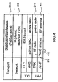
- Figure 4 represents the communications layers of a DSS in a preferred embodiment of the invention.
- the protocol layering well-known to those skilled in the art is shown.
- the stack of the preferred embodiment is shown.
- the structure of the protocol layers is an important feature of the invention, which characterises a Mobile Ad-hoc NETwork (MANET) according to an embodiment of the invention and is now described.
- the transport layer is implemented by the publish-subscribe middleware, 2340, in the Processing and storage module, which has been described hereinabove in connection with figure 2 .
- the network layer is IP-based and requires the following capabilities, 410:
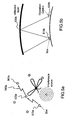
- Figures 5a and 5b illustrate the operation of the communications in a DSS in a preferred embodiment of the invention.
- Figure 5a illustrates the operation of LOS radios in a DSS.
- a node, 510a has 3 peers, 520a, 530a, 540a located within range of the BF antenna of the LOS radio, to which radiated power is focussed in beams for purpose of communication.
- the BF-antenna locks the beam to the peers as long as they are within LOS. This property is beneficial both when the peers move, and when the node's orientation w.r.t. northerly changes.
- Figure 5b illustrates the operation of a NLOS radio of a node 51 0b which can communicate with the OC, 520b, through the reflection layer, 530b.
- Figure 6 illustrates the inter-node operation of the communications in a DSS in a preferred embodiment of the invention.
- Another important feature of the system of the invention is to provide a canonical mechanism to distribute execution of applications over a group of Boxes of the DSS, a group being at least two Boxes of the DSS and at most all Boxes of the DSS.
- This mechanism contains the following three parts:
- the local execution is the fusion of sensor data at Box level, resulting in local surveillance picture.
- the group execution is the fusion of the local pictures of a group of Boxes into a group surveillance picture. Boxes can have either or both of two roles: Feeder and Collector.
- Feeder and Collector In figure 7a the situation is shown in which a Box has both roles.
- Figure 7b the situation is shown in which a Box has only the Feeder role, and in Figure 7c the Box has only the Collector role.
- the local execution is performed by the Box Fusion process, 2320, based on data captured by the Box' sensors, and processed in the adaptation process, 2310.
- the group execution is performed by a Collector, which collects the local fusion data, sent by all Feeders, to which the Collector has subscribed, and inputting it into a Group Fusion module, 630. Data is transferred from the Feeders to the Collector through Distribution middleware, 2340, 610, which communicate through the wireless WAN (LOS or NLOS radio links as explained hereinabove).
- a Collector which collects the local fusion data, sent by all Feeders, to which the Collector has subscribed, and inputting it into a Group Fusion module, 630.
- Data is transferred from the Feeders to the Collector through Distribution middleware, 2340, 610, which communicate through the wireless WAN (LOS or NLOS radio links as explained hereinabove).
- Data flows are controlled by Box Control module, 2330 and DSS Control module, 640. Both local execution and group execution of kinematic fusion is performed using algorithms known to the man skilled in the art, an example of which is given within the comments in relation to figures 7a .
- the Pub/Sub agent is capable of allowing a node to subscribe to certain data. A process for performing publication/subscription in a preferred manner used in this invention is described in European patent application No. EP1 0152278.7 filed this same day by the same applicant.
- the publishing node may announce to be published data using the Session Description Protocol (SDP) and/or the Session Announcement Protocol (SAP).
- SDP Session Description Protocol
- SAP Session Announcement Protocol
- the step of subscribing to data of interest to the node is performed by using the Internet Group Management Protocol (IGMP).
- IGMP Internet Group Management Protocol
- Kinematic fusion processes are processes whereby a single Box, acting on a stand alone basis or acting as a Collector from information possibly provided by multiple Feeders, compute a surveillance picture which provides information on tracks of targets computed from multiple sensors and/or multiple Boxes.
- the surveillance picture possibly supplemented with non real time data, such as information reports, will result in a Common Operational Picture or a COP to be displayed locally or at Collector level.
- FIG 7a a group kinematic fusion process of a system according to the invention is illustrated.
- a Collector, 710a performs a local fusion in its Box Fusion process, 2320, from the Box sensors S 1 ...S n , using algorithms known to the man skilled in the art.
- This Collector receives information from other Boxes through its Distribution middleware, 610. It then performs group fusion in its Group Fusion process, 630 from the output of the Box Fusion module, 2320, and of the other Boxes.
- the allocation of roles (Feeder, Collector) to Boxes allows for selection of a centralised or a distributed mode of operation: In a centralised mode, all Boxes within a group contribute their information to a Collector Box which processes it all and either displays locally a common surveillance/full operational picture or transfers it to an OC. In a distributed mode, all Boxes use the information of all the Boxes in the group to compute and display locally common surveillance/full operational picture.
- the canonical mechanism is applied to information fusion or Intention Detection, which is a process whereby the likelihood of a presumed intention of a suspect object related to a track, called a hypothesis, is determined using a probabilistic approach.
- the fusion processes in this application are therefore called estimation.
- the local execution is performed by the Individual estimation process, 820, which fuses so-called evidence, whose availability is further discussed hereunder, and outputs the local likelihood of a pre-defined hypothesis, for example the occurrence of a piracy attack on an object.
- the group execution is performed by the Collaborative estimation process, 830, with the local likelihood of neighbouring Boxes as input evidence, and with the group likelihood of a hypothesis as output.
- the evidence E 1 ...E n play the same role in intention detection as the sensors do in the kinematic fusion.
- Each individual element E i is individually and independently produced.
- the Individual Estimation process, 820, and the Collaborative Estimation process, 830, are also described further down in relation with figure 8 and figure 9 .
- Intention detection may be useful for counter-piracy missions in which High Value Units (HVU) must be protected against piracy attacks.
- Useful pictures of the crew and their potential weapons of a suspect target may serve as evidence, 940, for the individual estimation process, 820.
- Kinematic information (local surveillance picture), 910 serves as evidence, 940, after being processed, for example by a rule-based anomaly engine, 930. Based on a set of rules which are included in this rule-based anomaly engine, a set of possible events are determined.
- An example of a rule-based anomaly engine is disclosed by the European patent application published under n° EP2081163 which is assigned to the applicant of the instant application.
- engine 930 can be detected by engine 930 from various inputs: validity check of AIS information; violation of an alert area, a warning area, a keep out area; kinematics investigation; history footprint evaluation; tactical risk analysis; deviation from route plan; trade pattern analysis; rendez-vous recognition; reaction elicit; deviation from standard track.
- Evidence 940
- Said causal reasoning engine is best implemented, in a preferred embodiment of the system of the invention, using probabilistic models, for instance Bayesian networks.
- belief propagation algorithms are implemented in a manner, which is known to the man skilled in the art to calculate the likelihood, 860, of a hypothesis.
- the Bayesian network of the causal reasoning engine can be fed with soft-evidence, being the local likelihoods, each calculated by and retrieved from a number of collaborative Boxes.
- This causal reasoning engine then performs the collaborative estimation 830.
- Boxes positioned on different platforms, said Boxes being composed of different sensors, will greatly improve the diversity and independence of the data input into the collaborative Bayesian network and, therefore, the reliability of group likelihood, 860.
- intention detection of an object is preferably implemented in a DSS according to the invention.
- the likelihood of predefined hypothesis intentions is calculated by the causal reasoning component using various forms of evidence as input.
- evidence obtained by visual inspection of suspect objects.
- Such visual inspection is generally called reconnaissance, which can be included within DSS. It is implemented in various ways, two of which are described below. In both situations it is assumed that, based on their kinematic behavior as detected by sensors of the DSS, an object (the adversary) is suspected of threatening another object (the victim) under protection of the system.
- EO-cameras are included in Boxes. The Boxes completely or partly surrounding an adversary can take snapshots when the adversary is within range of the EO-camera.
- the UAV is of a hand-launched type so that it is able to launch it from relatively small response platforms like Fast Intercept Crafts (FIC). Recovery of such UAVs is possible by sea landing. Though the launching platform may be far from the location of the adversary, the UAV will be part of the DSS network because it will always be connected to the Box that tracks the adversary. At a height of up to hundred meters and being quiet, the UAV can covertly take snapshots from the adversary. These snapshots are routed through the DSS network to provide evidence, which is input to the intention detection capability.
- FIC Fast Intercept Crafts
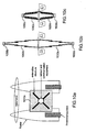
- FIG 10a, 10b and 10c represent three views of an Unmanned Surface Vehicle for use as a projection surveillance platform in an embodiment of the invention.
- an embodiment of particular interest in the context of the current invention is a specific Unmanned Surface Vehicle (USV) as a platform for a Box.
- USVs are interesting platforms for their unmanned and therefore cheap operation with long uninterrupted operational shifts.
- USVs are not of interest as a platform for sensors, and thus also for DSS, because of the relatively small height that the sensors can be positioned at. Higher positioning of the sensors renders the USV unstable in its pitch movement, which hampers severely sensor operation.
- USVs are modified to incorporate an inventive physical structure, which positions the sensor and communication equipment at the appropriate positions, and also provides the required pitch stability.
- a catamaran 1010a can be modified to include an extensible stem, 1020b, 1020c, and an extensible mast, 1040b, 1040c.
- the physical structure enables extension into the water, known as the extensible stem, 1020b, 1020c.
- This positions a sonar sensor 1030b, 1030c (PS-module) at the appropriate depth, and provides stability to the platform as a whole by applying a ballast weight to the lowest part of the extensible stem.
- the physical structure further enables extension into the air, known as the extensible mast, 1040b, 1040c.
- This positions the Box, 1050b, 1050c at the appropriate height.
- the stem and the mast consist of 3-4 sections of 3-4m each, so that the extended length corresponds to the height and depth as used with other platforms.
- There are various mechanisms to extend the mast which are all well known to those skilled in the art. Possible mechanisms include telescoping the segments and unfolding the segments.
- Simultaneous extension of the stem and the mast is achieved by coupling the extension mechanisms of the stem and the mast.
- a possible coupling mechanism uses gravity, i.e., when the stem is released the weight of the ballast at the same time drags the telescopic segments of the stem downwards and may at the same time send hydraulic pressure upwards to deploy the telescopic segments of the mast.
- Said physical structure can only be coupled when it can freely extend both into the water and into the air.
- the floater structure and hull of most USVs prevents such coupled extension. Due to the space between its floaters, this is not the case of a catamaran, which proves to be an excellent platform for such a physical structure.
- the EO module of the Box carried by an UAV/USV to confirm by direct visual inspection the information about a potential threat in the area where the UAV/USV is sent.
- the data from the EO module and the other modules of the Box on board the UAV/USV can then be input in the collaborative intention detection module of a group of nodes associated to the projection platform, thus greatly increasing reliability of detection and reconnaissance and the available response time.
- FIGS 11a, 11b and 11c illustrate the cooperation of Boxes organised in groups in an embodiment of the invention.
- a DSS of the invention consists of N Boxes, Box 1 ...Box i ... Box N .
- the N Boxes can be organised in groups at n hierarchical levels, where the group performs Group Fusion and/or Collaborative Estimation.
- Such groupings are mappings on the physical set of Boxes constituting the DSS.
- Figure 11.a shows a DSS, 1110a, which comprises two hierarchical levels: an upper level comprising one group only G 1,1 , 1120a, which comprises Boxes 1121 a, 1122a, 1123a, 1124a and 1125a; and a lower level comprising three groups G 0,1 , G 0,2 , G 0,3 .
- group G 0,1 , 1130a comprises Boxes 1131 a, 1123a, 1133a and 1134a.
- a group comprises at least one Box, which acts as a gateway for the group (Group Gateway or GG).
- a group gateway speaks on behalf of the group in a hierarchically higher level. Therefore, GG 1134a and GG 1121 a are one and the same Box.
- FIGs 11b and 11c illustrate the recursive application of the said canonical mechanism to obtain inter-group operation.
- GGs of level i form, possibly with one or more other Boxes, a group Gi+1,k at level i+1.
- the GGs perform the Feeder role at level i and the Collector role at level i+1.
- the latter is for the purpose of performing Group Fusion or Collaborative Estimation in a hierarchically manner.
- the GGs may also act as a hierarchical Feeder, only sending data to a higher level OC, as exemplified by Figure 11.c .
- a hierarchical group structure allows excellent scalability of the system of the invention through partitioning (m x n instead of N x N communications) and layering (less data sent to higher levels).
- the system of the invention may operate in a peer mode (which is a one group system). Such a system operates preferably in a distributed mode. It is highly robust but not scalable because all Boxes are active at the same time.
- the system of the invention also provides excellent flexibility to the following aspects:
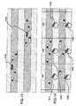
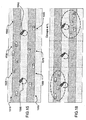
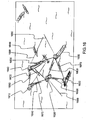
- FIGS 12 through 16 illustrate five Concepts of Operation (CONOPS) for counter piracy missions. They will be commented upon jointly hereunder.
- a specific CONOPS defines for instance in the context of a specific mission the Project Statement, the Proposed Solution, the Proposed Support Environment, the Operating Concept and the Operational scenarios (see for example European patent application n ° EP2081163 already cited). Since all the missions of protecting High-Value Units (HVUs) against piracy attack as illustrated in figures 12 through 16 have much in common, the CONOPS will mostly differ in their Operational scenarios. Some commonalities in the CONOPSes to use this invention have already been described.
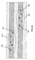
- HVUs In the first example of figure 12 , HVUs travel in convoys 1210, 1220. The Boxes are located on some of the HVUs, 1211, 1212, 1221, 1222. Each HVU receives a local Surveillance Picture (SP) from all other HVUs in the convoy.
- SP Surveillance Picture
- SA Situation Awareness
- SA is improved by fusion and/or intention detection performed at convoy level, but HVUs can only respond to a threat by evasive action.
- each convoy 1210, 1220 is accompanied by a navy ship 1310, 1320 which at the same time carries a Box and is a response platform.
- the navy ships get a convoy SP and the scope of their SA is their convoy.
- the navy ships provide response capabilities, which are improved in comparison to solutions of the prior art by the cooperation between the nodes of each convoy.
- the third example of figure 14 is a shipping lane divided in zones (each zone has been defined with a width of around 30 NM in the example of the figure by taking into consideration the required response time and the interconnectivity). There is a Box on each HVU (only some of them when the HVUs travel in convoys). At least one navy ship 1410, 1420, 1430, 1440, 1450, 1460 is responsible for a zone. They will normally not patrol too long distances to save on fuel. The scope of the SA is the zone.
- the fourth example of figure 15 is a shipping lane.
- fixed platforms (spar-type buoys for instance) 1510, 1520, 1530, 1540, 1550, 1560, 1570, 1580 are deployed along the lane to form a corridor.
- Navy ships 1590, 15A0 in an adequate number for a required response time are positioned within the corridor.
- the navy ships can respond to any incident in time.
- Platforms are positioned to provide early warning.
- the SA scope is the zone.
- FIG 16 illustrates the CONOPS of the second example ( Figure 13 ) in a more detailed manner.
- frigates are equipped with helicopters. Shipping companies rightfully state that security at sea is the responsibility of the navies, and that they will therefore not take equipment on board to provide security. Navies, on the other hand, may claim to offer cost-effective security to the HVUs when they host capabilities for extended surveillance. Therefore, a DSS approach to counter-piracy uses the HVUs themselves as platforms for the Boxes. A convoy of HVUs then forms the extended surveillance capability.
- frigates that carry helicopters are used as C2 and response platforms, but now their number is solely determined by the required response time and the velocity of the used response resources.
- the number of frigates with helicopters is only three.
- the Boxes are deployed on both the HVUs 1610, 1620 and the frigates 1630, 1640,1650.
- the beams 16A0, 16B0, 16C0, 16D0, 16E0, 16F0, 16G0 represent the sensing capabilities and the flashes 1660, 1670, 1680, 1690 represent the communication among Boxes.
- the figure captures the moment where the approaching fast boat 16H0 has already been classified as a threat and the helicopter has taken off for counter measures.
- An alternative to frigates is to use Fast Intercept Crafts (FIC) as C2 and response platform. Due to their lower speed than the helicopters on frigates, a larger number of FICs is required. But since FICs have dramatic lower operating cost than frigates, the total C4ISR operating cost decreases significantly.
- FIC Fast Intercept Crafts
- Figure 17 illustrates a fifth CONOPS for use of a DSS in an embodiment of the invention.
- the scenario is the threatening of a nation's integrity due to a dispute over their natural resources.
- Oil fields provide the means to access these natural resources.
- an oil field in the Arabic Gulf consisting of several oilrigs 1710, 1720, 1730, a loading terminal 1740 and oil pipes 1750, 1760, 1770 interconnecting them as displayed on the figure.
- Such a structure can be prone to terrorism or capture.
- the total area covered by an oil field can be 100x100km, which requires an extended surveillance capability for continuous and complete surveillance.
- the Boxes can be positioned on the rigs.
- Boxes can be positioned on spar-buoys 1780, 1790, 17A0, 17B0. Even a combination of rigs and buoys is possible, as shown in the figure. Like in the illustrations of counter-piracy of figure 16 , the beams indicate surveillance and the flashes indicate communication. In addition, the buoys have passive sonar indicated by the concentric circles. The threat is formed by a couple of divers suspected to sabotage an oilrig. The divers have been transported by jetski's, which have been detected by both the radar and the sonar. FICs are chosen as C2 and response platforms (not shown in the figure). The size of the oil field and the required response time determine the number of FICs needed. Each of the FICs can 'tap' only the data from the extended surveillance capability that is relevant to its portion of the oil field. The FIC closest to the threat will take appropriate counter-measures.
- FIG. 18 through 20 illustrate examples of zoning approaches by a DSS in various embodiments of the invention. They will be commented upon jointly hereunder.
- a key feature of the system of the invention is to provide scalable and reconfigurable zone approaches. To provide these features, the system makes use of the underlying topology of the ad-hoc network made up by the DSS-nodes. The network as a whole remains untouched, while the application acts on subsets of the network. Important basic information for the applications is the topology database, which contains the geographic position of each node, and the type of node (surveillance, response, or both). Input for such a database can be achieved by modifying the routing process to include geo-position and node-type in the routing message exchange.
- the common denominator of all such applications is that the subscription behaviour of a node running an application is determined by a geographic or rule-based function of the topology:
Landscapes
- Engineering & Computer Science (AREA)
- Computer Networks & Wireless Communication (AREA)
- Radar, Positioning & Navigation (AREA)
- Remote Sensing (AREA)
- Physics & Mathematics (AREA)
- General Physics & Mathematics (AREA)
- Health & Medical Sciences (AREA)
- Computing Systems (AREA)
- General Health & Medical Sciences (AREA)
- Medical Informatics (AREA)
- Signal Processing (AREA)
- Alarm Systems (AREA)
Claims (20)
- Système distribué de surveillance comprenant un groupe d'au moins un premier (10i) et un second (10j) noeud, comprenant chacun au moins deux capteurs (310a, 320a, 320b, 340b), un module de référence (330a, 330b), un module de communication (340a, 310b) configuré pour exécuter un processus de publication/abonnement (2350) en vertu duquel ledit premier noeud est configuré pour publier des données destinées à être utilisées par au moins ledit second noeud et pour s'abonner à des données publiées par au moins ledit second noeud et un module de traitement et de stockage (350a, 310b) configuré pour générer une image opérationnelle locale à partir desdites données du premier noeud et/ou une image opérationnelle de groupe (250) à partir d'au moins certaines des données locales/de groupe d'abonnement stockées dans ledit module de traitement et de stockage depuis ledit module de communication, ledit système étant caractérisé en ce que les au moins premier et second noeuds sont configurés pour former automatiquement une entité de surveillance collaborative et s'abonner /se désabonner à des données en fonction d'au moins des plages définies autour desdits noeuds.
- Système distribué de surveillance selon la revendication 1, caractérisé en ce que chaque noeud comprend au moins deux capteurs choisis dans un groupe comprenant un radar, un AIS, un capteur électro-optique, un sonar passif, un goniomètre sonore, un radiogoniomètre et des mesures de soutien électronique (ESM).
- Système distribué de surveillance selon l'une quelconque des revendications 1 à 2, caractérisé en ce que l'un des noeuds est porté par une plate-forme USV (1010a).
- Système distribué de surveillance selon la revendication 3, caractérisé en ce que ladite plate-forme USV est un catamaran équipé d'un mât télescopique (1040b, 1040c) portant au moins un capteur d'antenne et un tube télescopique (1020b, 1020c) portant au moins un capteur sonar (1 030b, 1030c).
- Système distribué de surveillance selon la revendication 4, caractérisé en ce que ledit mât télescopique et ledit tube télescopique sont rétractés lorsque ledit catamaran est en mode transport et sont conjointement déployés grâce à un mécanisme de couplage avant que lesdits capteurs ne fonctionnent dans le mode d'observation.
- Système distribué de surveillance selon l'une quelconque des revendications 1 à 5, caractérisé en ce que ledit système est adapté pour être en communication avec un système de commande et de contrôle (120) pour commander et contrôler les capacités de réponse (130).
- Système distribué de surveillance selon l'une quelconque des revendications 1 à 6, caractérisé en ce que ledit module de communication comprend une liaison LOS (211) et une liaison NLOS (212).
- Système distribué de surveillance selon l'une quelconque des revendications 1 à 7, caractérisé en ce que, dans ledit processus de publication/abonnement, les données sont acheminées depuis les noeuds producteurs de données vers les noeuds consommateurs de données en suivant une arborescence de distribution biunivoque ou injective.
- Système distribué de surveillance selon l'une quelconque des revendications 1 à 8, caractérisé en ce que ledit module de traitement et de stockage (350a, 310b) est en outre configuré pour exécuter un processus de détection d'intention dans lequel des éléments de preuve indépendants sont fusionnés pour calculer la probabilité d'une hypothèse (860).
- Système distribué de surveillance selon la revendication 9, caractérisé en ce que ledit processus de détection d'intention utilise un sous-processus de détection d'anomalies à base de règles (930) pour calculer lesdits éléments de preuve.
- Système distribué de surveillance selon la revendication 10, caractérisé en ce que lesdits éléments de preuve sont entrés dans un sous-processus de raisonnement causal (950) basé sur des réseaux de Bayes, ledit sous-processus de raisonnement causal s'exécutant dans le module de traitement et de stockage d'un premier noeud et étant configuré pour recevoir comme entrée la probabilité locale (860) d'au moins un second noeud et produisant comme sortie du réseau de Bayes de l'estimation collaborative dudit premier noeud, la probabilité de groupe d'une hypothèse.
- Système distribué de surveillance selon l'une quelconque des revendications 1 à 11, caractérisé en ce que ledit groupe (1120a) de noeuds est configuré pour être en communication avec une structure hiérarchique d'autres groupes (1130a, 1140a, 1150a) par le biais de passerelles de groupes (1121 a, 1134a ; 1124a, 1154a ; 1125a, 1144a).
- Procédé de surveillance distribué comprenant un groupe d'au moins un premier et un second processus d'observation, lesdits processus comprenant chacun au moins deux sous-processus de détection, un sous-processus de référencement, un sous-processus de communication, en vertu desquels ledit premier processus d'observation publie des données destinées à être utilisées par au moins ledit second processus d'observation et peut s'abonner à des données publiées par au moins ledit second processus d'observation et un sous-processus de calcul et de stockage capable de générer une image opérationnelle locale à partir de données produites par ledit premier processus d'observation et/ou une image opérationnelle de groupe à partir d'au moins certaines des données d'abonnement provenant du groupe stocké par ledit sous-processus de traitement et de stockage dudit sous-processus de communication, ledit procédé étant caractérisé en ce qu'au moins certains des processus d'observation sont configurés pour former automatiquement des groupes de processus de surveillance collaborative et pour s'abonner/se désabonner à des données à l'intérieur de chaque groupe en fonction d'au moins des plages définies autour de noeuds exécutant les processus de surveillance.
- Procédé de surveillance distribué selon la revendication 13, caractérisé en ce qu'au moins certains des processus d'observation s'exécutent sur un sous-ensemble d'un groupe de navires à protéger qui naviguent dans un convoi non protégé.
- Procédé de surveillance distribué selon la revendication 13, caractérisé en ce qu'au moins certains des processus d'observation s'exécutent sur un sous-ensemble d'un groupe de navires à protéger et sur des navires de protection qui naviguent en convoi.
- Procédé de surveillance distribué selon la revendication 13, caractérisé en ce qu'au moins certains des processus d'observation s'exécutent sur des navires à protéger et sur des navires de protection navigant chacun dans une zone de responsabilité.
- Procédé de surveillance distribué selon la revendication 13, caractérisé en ce qu'au moins certains des processus d'observation s'exécutent sur des navires de protection navigant chacun dans une zone de responsabilité et sur des plates-formes fixes positionnées dans un couloir devant être protégé.
- Procédé de surveillance distribué selon l'une quelconque des revendications 13 à 17, caractérisé en ce qu'au moins certains des processus d'observation sont configurés pour utiliser des données d'entrée issues d'une pluralité de noeuds.
- Procédé de surveillance distribué selon la revendication 18, caractérisé en ce qu'au moins certains de ladite pluralité de noeuds s'abonnent aux données générées grâce aux processus d'observation d'au moins certains des autres noeuds parmi ladite pluralité de noeuds.
- Procédé de surveillance distribué selon la revendication 18, caractérisé en ce qu'au moins certains de ladite pluralité de noeuds envoient des données sous forme d'entrée à un processus d'observation d'un seul noeud parmi ladite pluralité de noeuds.
Priority Applications (2)
| Application Number | Priority Date | Filing Date | Title |
|---|---|---|---|
| EP10152301A EP2355451B1 (fr) | 2010-02-01 | 2010-02-01 | Système distribué de surveillance maritime |
| PCT/EP2011/051001 WO2011092167A1 (fr) | 2010-02-01 | 2011-01-25 | Système de surveillance maritime distribué |
Applications Claiming Priority (1)
| Application Number | Priority Date | Filing Date | Title |
|---|---|---|---|
| EP10152301A EP2355451B1 (fr) | 2010-02-01 | 2010-02-01 | Système distribué de surveillance maritime |
Publications (2)
| Publication Number | Publication Date |
|---|---|
| EP2355451A1 EP2355451A1 (fr) | 2011-08-10 |
| EP2355451B1 true EP2355451B1 (fr) | 2013-01-09 |
Family
ID=42341361
Family Applications (1)
| Application Number | Title | Priority Date | Filing Date |
|---|---|---|---|
| EP10152301A Revoked EP2355451B1 (fr) | 2010-02-01 | 2010-02-01 | Système distribué de surveillance maritime |
Country Status (2)
| Country | Link |
|---|---|
| EP (1) | EP2355451B1 (fr) |
| WO (1) | WO2011092167A1 (fr) |
Cited By (4)
| Publication number | Priority date | Publication date | Assignee | Title |
|---|---|---|---|---|
| WO2016036312A1 (fr) * | 2014-09-04 | 2016-03-10 | Concorde Asia Pte. Ltd. | Système et procédé de surveillance de sécurité en mer |
| US10379218B1 (en) | 2016-04-19 | 2019-08-13 | Scientific Innovations, Inc. | Self-locating system and methods for multistatic active coherent sonar |
| US11423667B1 (en) * | 2021-12-31 | 2022-08-23 | Sea Machines Robotics, Inc. | Geolocating an object using a single camera |
| US11734590B2 (en) | 2020-06-16 | 2023-08-22 | Northrop Grumman Systems Corporation | System and method for automating observe-orient-decide-act (OODA) loop enabling cognitive autonomous agent systems |
Families Citing this family (13)
| Publication number | Priority date | Publication date | Assignee | Title |
|---|---|---|---|---|
| DE102012213881A1 (de) | 2012-08-06 | 2014-02-06 | Thales Deutschland Gmbh | Vorrichtung zum Erfassen und/oder Überwachen eines Umfelds eines Seefahrzeugs |
| US10285141B1 (en) | 2012-09-19 | 2019-05-07 | Safeco Insurance Company Of America | Data synchronization across multiple sensors |
| RU2558666C2 (ru) * | 2013-11-06 | 2015-08-10 | Закрытое акционерное общество "Научно-производственный центр "Аквамарин" | Многопозиционный комплекс с автономными радиолокационными терминалами и гидроакустическими зондами для мониторинга надводного, подводного и воздушного пространства акваторий |
| ES2899311T3 (es) * | 2017-07-07 | 2022-03-10 | Bae Systems Plc | Posicionamiento de un conjunto de vehículos |
| EP3425337A1 (fr) * | 2017-07-07 | 2019-01-09 | BAE SYSTEMS plc | Positionnement d'un ensemble de véhicules |
| WO2019035877A2 (fr) * | 2017-08-15 | 2019-02-21 | Blue Skies Holdings, Llc, D/B/A Blue Skies Ocean Systems | Système et procédé permettant de détecter des menaces contre des biens commerciaux maritimes, l'environnement et l'infrastructure industrielle/commerciale côtière |
| CN108415414B (zh) * | 2018-01-12 | 2021-04-27 | 伍斯龙 | 一种分布式自动行车导航系统 |
| KR102723325B1 (ko) * | 2022-07-04 | 2024-10-29 | 엘아이지넥스원 주식회사 | 음향 정보 공유 방법 및 그를 위한 장치 |
| GR1010558B (el) * | 2022-12-28 | 2023-10-16 | A.S. Prote Maritime Ltd Ιδιωτικη Επιχειρηση Παροχης Υπηρεσιων Ασφαλειας & Συμβουλευτικων Υπηρεσιων, | Συστημα επιτηρησης θαλασσιων περιοχων με τη χρηση συστηματων μη επανδρωμενων αεροσκαφων (σμηεα) για την αποφυγη και προληψη της πειρατειας σε εμπορικα πλοια |
| CN117579666B (zh) * | 2024-01-17 | 2024-03-19 | 北京恒润安科技有限公司 | 一种基于云平台的水库防汛抗旱应急管理系统 |
| EP4644943A1 (fr) * | 2024-05-02 | 2025-11-05 | BAE SYSTEMS plc | Améliorations apportées à des systèmes radar et relatives à ceux-ci |
| GB2640717A (en) * | 2024-05-02 | 2025-11-05 | Bae Systems Plc | Improvements in and relating to RADAR systems |
| WO2025229313A1 (fr) * | 2024-05-02 | 2025-11-06 | Bae Systems Plc | Améliorations apportées à des systèmes radar et se rapportant à ceux-ci |
Family Cites Families (1)
| Publication number | Priority date | Publication date | Assignee | Title |
|---|---|---|---|---|
| ATE531019T1 (de) | 2008-01-21 | 2011-11-15 | Thales Nederland Bv | Sicherheits- und sicherungssystem gegen mehrfachbedrohung und bestimmungsverfahren dafür |
-
2010
- 2010-02-01 EP EP10152301A patent/EP2355451B1/fr not_active Revoked
-
2011
- 2011-01-25 WO PCT/EP2011/051001 patent/WO2011092167A1/fr not_active Ceased
Cited By (7)
| Publication number | Priority date | Publication date | Assignee | Title |
|---|---|---|---|---|
| WO2016036312A1 (fr) * | 2014-09-04 | 2016-03-10 | Concorde Asia Pte. Ltd. | Système et procédé de surveillance de sécurité en mer |
| US9953513B2 (en) | 2014-09-04 | 2018-04-24 | Concorde Asia Pte. Ltd. | Offshore security monitoring system and method |
| EP3188964A4 (fr) * | 2014-09-04 | 2018-06-13 | Concorde Asia Pte. Ltd. | Système et procédé de surveillance de sécurité en mer |
| US10379218B1 (en) | 2016-04-19 | 2019-08-13 | Scientific Innovations, Inc. | Self-locating system and methods for multistatic active coherent sonar |
| US11734590B2 (en) | 2020-06-16 | 2023-08-22 | Northrop Grumman Systems Corporation | System and method for automating observe-orient-decide-act (OODA) loop enabling cognitive autonomous agent systems |
| US11423667B1 (en) * | 2021-12-31 | 2022-08-23 | Sea Machines Robotics, Inc. | Geolocating an object using a single camera |
| WO2023129699A1 (fr) * | 2021-12-31 | 2023-07-06 | Sea Machines Robotics, Inc. | Géolocalisation d'un objet à l'aide d'une seule caméra |
Also Published As
| Publication number | Publication date |
|---|---|
| WO2011092167A1 (fr) | 2011-08-04 |
| EP2355451A1 (fr) | 2011-08-10 |
Similar Documents
| Publication | Publication Date | Title |
|---|---|---|
| EP2355451B1 (fr) | Système distribué de surveillance maritime | |
| Höyhtyä et al. | Connectivity for autonomous ships: Architecture, use cases, and research challenges | |
| Rødseth et al. | Communication architecture for an unmanned merchant ship | |
| Carson-Jackson | Satellite AIS–developing technology or existing capability? | |
| US11171713B2 (en) | Wireless communication relay system for unmanned vehicles | |
| US20160147223A1 (en) | System and Method for Control of Autonomous Marine Vessels | |
| Wahl et al. | New possible roles of small satellites in maritime surveillance | |
| NO333567B1 (no) | Fremgangsmate og system for maritim, hoyhastighets bredbandskommunikasjonsnettverk-oppbygging | |
| CN119380583A (zh) | 多网融合船岸通信系统及基于船舶物联网的智能船舶远程驾驶控制系统 | |
| Plass et al. | Current situation and future innovations in Arctic communications | |
| Cairns | AIS and long range identification & tracking | |
| Soldi et al. | Monitoring of underwater critical infrastructures: The Nord Stream and other recent case studies | |
| EP2329291B1 (fr) | Capteurs à l unisson pour une surveillance maritime | |
| Sarkodie et al. | A survey of advanced marine communication and navigation technologies: developments and strategies | |
| RU125723U1 (ru) | Береговая пространственно распределенная многопозиционная радиолокационная станция с автономными радиолокационными терминалами для мониторинга акваторий | |
| KR102120779B1 (ko) | 무인기를 이용한 해수면 모니터링 방법 및 장치 | |
| JP2024145783A (ja) | 航行支援システム、仮想基地局、船舶情報端末、航行支援方法及びプログラム | |
| Nohara et al. | Affordable high-performance radar networks for homeland security applications | |
| CN116088367A (zh) | 一种无人舰艇航行控制系统、方法、计算机设备及介质 | |
| Ilcev | Integration of Maritime Radio and Satellite Automatic Identification Systems (AIS). | |
| RU2558666C2 (ru) | Многопозиционный комплекс с автономными радиолокационными терминалами и гидроакустическими зондами для мониторинга надводного, подводного и воздушного пространства акваторий | |
| CN115623024A (zh) | 基于卫星通信的智能无人艇群海上应用系统及工作方法 | |
| Hasbi | Maritime surveillance with small satellites | |
| Healey et al. | Collaborative unmanned vehicles for maritime domain awareness | |
| RU125720U1 (ru) | Береговая пространственно распределенная многопозиционная радиолокационная станция с автономными радиолокационными терминалами для мониторинга акваторий |
Legal Events
| Date | Code | Title | Description |
|---|---|---|---|
| PUAI | Public reference made under article 153(3) epc to a published international application that has entered the european phase |
Free format text: ORIGINAL CODE: 0009012 |
|
| AK | Designated contracting states |
Kind code of ref document: A1 Designated state(s): AT BE BG CH CY CZ DE DK EE ES FI FR GB GR HR HU IE IS IT LI LT LU LV MC MK MT NL NO PL PT RO SE SI SK SM TR |
|
| AX | Request for extension of the european patent |
Extension state: AL BA RS |
|
| 17P | Request for examination filed |
Effective date: 20120210 |
|
| GRAP | Despatch of communication of intention to grant a patent |
Free format text: ORIGINAL CODE: EPIDOSNIGR1 |
|
| GRAS | Grant fee paid |
Free format text: ORIGINAL CODE: EPIDOSNIGR3 |
|
| GRAC | Information related to communication of intention to grant a patent modified |
Free format text: ORIGINAL CODE: EPIDOSCIGR1 |
|
| GRAA | (expected) grant |
Free format text: ORIGINAL CODE: 0009210 |
|
| AK | Designated contracting states |
Kind code of ref document: B1 Designated state(s): AT BE BG CH CY CZ DE DK EE ES FI FR GB GR HR HU IE IS IT LI LT LU LV MC MK MT NL NO PL PT RO SE SI SK SM TR |
|
| REG | Reference to a national code |
Ref country code: GB Ref legal event code: FG4D |
|
| REG | Reference to a national code |
Ref country code: AT Ref legal event code: REF Ref document number: 593297 Country of ref document: AT Kind code of ref document: T Effective date: 20130115 Ref country code: CH Ref legal event code: EP |
|
| REG | Reference to a national code |
Ref country code: IE Ref legal event code: FG4D |
|
| REG | Reference to a national code |
Ref country code: DE Ref legal event code: R096 Ref document number: 602010004475 Country of ref document: DE Effective date: 20130314 |
|
| REG | Reference to a national code |
Ref country code: SE Ref legal event code: TRGR |
|
| REG | Reference to a national code |
Ref country code: NL Ref legal event code: T3 |
|
| PG25 | Lapsed in a contracting state [announced via postgrant information from national office to epo] |
Ref country code: SI Free format text: LAPSE BECAUSE OF FAILURE TO SUBMIT A TRANSLATION OF THE DESCRIPTION OR TO PAY THE FEE WITHIN THE PRESCRIBED TIME-LIMIT Effective date: 20130109 |
|
| REG | Reference to a national code |
Ref country code: AT Ref legal event code: MK05 Ref document number: 593297 Country of ref document: AT Kind code of ref document: T Effective date: 20130109 |
|
| REG | Reference to a national code |
Ref country code: LT Ref legal event code: MG4D |
|
| PG25 | Lapsed in a contracting state [announced via postgrant information from national office to epo] |
Ref country code: ES Free format text: LAPSE BECAUSE OF FAILURE TO SUBMIT A TRANSLATION OF THE DESCRIPTION OR TO PAY THE FEE WITHIN THE PRESCRIBED TIME-LIMIT Effective date: 20130420 Ref country code: BG Free format text: LAPSE BECAUSE OF FAILURE TO SUBMIT A TRANSLATION OF THE DESCRIPTION OR TO PAY THE FEE WITHIN THE PRESCRIBED TIME-LIMIT Effective date: 20130409 Ref country code: IS Free format text: LAPSE BECAUSE OF FAILURE TO SUBMIT A TRANSLATION OF THE DESCRIPTION OR TO PAY THE FEE WITHIN THE PRESCRIBED TIME-LIMIT Effective date: 20130509 Ref country code: BE Free format text: LAPSE BECAUSE OF FAILURE TO SUBMIT A TRANSLATION OF THE DESCRIPTION OR TO PAY THE FEE WITHIN THE PRESCRIBED TIME-LIMIT Effective date: 20130109 Ref country code: LT Free format text: LAPSE BECAUSE OF FAILURE TO SUBMIT A TRANSLATION OF THE DESCRIPTION OR TO PAY THE FEE WITHIN THE PRESCRIBED TIME-LIMIT Effective date: 20130109 Ref country code: NO Free format text: LAPSE BECAUSE OF FAILURE TO SUBMIT A TRANSLATION OF THE DESCRIPTION OR TO PAY THE FEE WITHIN THE PRESCRIBED TIME-LIMIT Effective date: 20130409 Ref country code: AT Free format text: LAPSE BECAUSE OF FAILURE TO SUBMIT A TRANSLATION OF THE DESCRIPTION OR TO PAY THE FEE WITHIN THE PRESCRIBED TIME-LIMIT Effective date: 20130109 |
|
| PG25 | Lapsed in a contracting state [announced via postgrant information from national office to epo] |
Ref country code: LV Free format text: LAPSE BECAUSE OF FAILURE TO SUBMIT A TRANSLATION OF THE DESCRIPTION OR TO PAY THE FEE WITHIN THE PRESCRIBED TIME-LIMIT Effective date: 20130109 Ref country code: PT Free format text: LAPSE BECAUSE OF FAILURE TO SUBMIT A TRANSLATION OF THE DESCRIPTION OR TO PAY THE FEE WITHIN THE PRESCRIBED TIME-LIMIT Effective date: 20130509 Ref country code: GR Free format text: LAPSE BECAUSE OF FAILURE TO SUBMIT A TRANSLATION OF THE DESCRIPTION OR TO PAY THE FEE WITHIN THE PRESCRIBED TIME-LIMIT Effective date: 20130410 Ref country code: PL Free format text: LAPSE BECAUSE OF FAILURE TO SUBMIT A TRANSLATION OF THE DESCRIPTION OR TO PAY THE FEE WITHIN THE PRESCRIBED TIME-LIMIT Effective date: 20130109 Ref country code: FI Free format text: LAPSE BECAUSE OF FAILURE TO SUBMIT A TRANSLATION OF THE DESCRIPTION OR TO PAY THE FEE WITHIN THE PRESCRIBED TIME-LIMIT Effective date: 20130109 |
|
| PG25 | Lapsed in a contracting state [announced via postgrant information from national office to epo] |
Ref country code: MC Free format text: LAPSE BECAUSE OF NON-PAYMENT OF DUE FEES Effective date: 20130228 Ref country code: HR Free format text: LAPSE BECAUSE OF FAILURE TO SUBMIT A TRANSLATION OF THE DESCRIPTION OR TO PAY THE FEE WITHIN THE PRESCRIBED TIME-LIMIT Effective date: 20130109 |
|
| PLBI | Opposition filed |
Free format text: ORIGINAL CODE: 0009260 |
|
| PG25 | Lapsed in a contracting state [announced via postgrant information from national office to epo] |
Ref country code: DK Free format text: LAPSE BECAUSE OF FAILURE TO SUBMIT A TRANSLATION OF THE DESCRIPTION OR TO PAY THE FEE WITHIN THE PRESCRIBED TIME-LIMIT Effective date: 20130109 Ref country code: CZ Free format text: LAPSE BECAUSE OF FAILURE TO SUBMIT A TRANSLATION OF THE DESCRIPTION OR TO PAY THE FEE WITHIN THE PRESCRIBED TIME-LIMIT Effective date: 20130109 Ref country code: RO Free format text: LAPSE BECAUSE OF FAILURE TO SUBMIT A TRANSLATION OF THE DESCRIPTION OR TO PAY THE FEE WITHIN THE PRESCRIBED TIME-LIMIT Effective date: 20130109 Ref country code: SK Free format text: LAPSE BECAUSE OF FAILURE TO SUBMIT A TRANSLATION OF THE DESCRIPTION OR TO PAY THE FEE WITHIN THE PRESCRIBED TIME-LIMIT Effective date: 20130109 Ref country code: EE Free format text: LAPSE BECAUSE OF FAILURE TO SUBMIT A TRANSLATION OF THE DESCRIPTION OR TO PAY THE FEE WITHIN THE PRESCRIBED TIME-LIMIT Effective date: 20130109 |
|
| PLAX | Notice of opposition and request to file observation + time limit sent |
Free format text: ORIGINAL CODE: EPIDOSNOBS2 |
|
| 26 | Opposition filed |
Opponent name: ATLAS ELEKTRONIK GMBH Effective date: 20131004 |
|
| PG25 | Lapsed in a contracting state [announced via postgrant information from national office to epo] |
Ref country code: CY Free format text: LAPSE BECAUSE OF FAILURE TO SUBMIT A TRANSLATION OF THE DESCRIPTION OR TO PAY THE FEE WITHIN THE PRESCRIBED TIME-LIMIT Effective date: 20130109 |
|
| REG | Reference to a national code |
Ref country code: IE Ref legal event code: MM4A |
|
| PG25 | Lapsed in a contracting state [announced via postgrant information from national office to epo] |
Ref country code: IT Free format text: LAPSE BECAUSE OF FAILURE TO SUBMIT A TRANSLATION OF THE DESCRIPTION OR TO PAY THE FEE WITHIN THE PRESCRIBED TIME-LIMIT Effective date: 20130109 |
|
| REG | Reference to a national code |
Ref country code: DE Ref legal event code: R026 Ref document number: 602010004475 Country of ref document: DE Effective date: 20131004 |
|
| PG25 | Lapsed in a contracting state [announced via postgrant information from national office to epo] |
Ref country code: IE Free format text: LAPSE BECAUSE OF NON-PAYMENT OF DUE FEES Effective date: 20130201 |
|
| PLAF | Information modified related to communication of a notice of opposition and request to file observations + time limit |
Free format text: ORIGINAL CODE: EPIDOSCOBS2 |
|
| PLBB | Reply of patent proprietor to notice(s) of opposition received |
Free format text: ORIGINAL CODE: EPIDOSNOBS3 |
|
| PG25 | Lapsed in a contracting state [announced via postgrant information from national office to epo] |
Ref country code: MT Free format text: LAPSE BECAUSE OF FAILURE TO SUBMIT A TRANSLATION OF THE DESCRIPTION OR TO PAY THE FEE WITHIN THE PRESCRIBED TIME-LIMIT Effective date: 20130109 |
|
| REG | Reference to a national code |
Ref country code: CH Ref legal event code: PL |
|
| PG25 | Lapsed in a contracting state [announced via postgrant information from national office to epo] |
Ref country code: LI Free format text: LAPSE BECAUSE OF NON-PAYMENT OF DUE FEES Effective date: 20140228 Ref country code: CH Free format text: LAPSE BECAUSE OF NON-PAYMENT OF DUE FEES Effective date: 20140228 |
|
| PG25 | Lapsed in a contracting state [announced via postgrant information from national office to epo] |
Ref country code: SM Free format text: LAPSE BECAUSE OF FAILURE TO SUBMIT A TRANSLATION OF THE DESCRIPTION OR TO PAY THE FEE WITHIN THE PRESCRIBED TIME-LIMIT Effective date: 20130109 |
|
| PG25 | Lapsed in a contracting state [announced via postgrant information from national office to epo] |
Ref country code: TR Free format text: LAPSE BECAUSE OF FAILURE TO SUBMIT A TRANSLATION OF THE DESCRIPTION OR TO PAY THE FEE WITHIN THE PRESCRIBED TIME-LIMIT Effective date: 20130109 |
|
| PG25 | Lapsed in a contracting state [announced via postgrant information from national office to epo] |
Ref country code: LU Free format text: LAPSE BECAUSE OF NON-PAYMENT OF DUE FEES Effective date: 20130201 Ref country code: MK Free format text: LAPSE BECAUSE OF FAILURE TO SUBMIT A TRANSLATION OF THE DESCRIPTION OR TO PAY THE FEE WITHIN THE PRESCRIBED TIME-LIMIT Effective date: 20130109 Ref country code: HU Free format text: LAPSE BECAUSE OF FAILURE TO SUBMIT A TRANSLATION OF THE DESCRIPTION OR TO PAY THE FEE WITHIN THE PRESCRIBED TIME-LIMIT; INVALID AB INITIO Effective date: 20100201 |
|
| REG | Reference to a national code |
Ref country code: FR Ref legal event code: PLFP Year of fee payment: 7 |
|
| RDAF | Communication despatched that patent is revoked |
Free format text: ORIGINAL CODE: EPIDOSNREV1 |
|
| STAA | Information on the status of an ep patent application or granted ep patent |
Free format text: STATUS: THE PATENT HAS BEEN GRANTED |
|
| REG | Reference to a national code |
Ref country code: FR Ref legal event code: PLFP Year of fee payment: 8 |
|
| APBM | Appeal reference recorded |
Free format text: ORIGINAL CODE: EPIDOSNREFNO |
|
| APBP | Date of receipt of notice of appeal recorded |
Free format text: ORIGINAL CODE: EPIDOSNNOA2O |
|
| APAH | Appeal reference modified |
Free format text: ORIGINAL CODE: EPIDOSCREFNO |
|
| APBQ | Date of receipt of statement of grounds of appeal recorded |
Free format text: ORIGINAL CODE: EPIDOSNNOA3O |
|
| REG | Reference to a national code |
Ref country code: FR Ref legal event code: PLFP Year of fee payment: 9 |
|
| PGFP | Annual fee paid to national office [announced via postgrant information from national office to epo] |
Ref country code: SE Payment date: 20200210 Year of fee payment: 11 Ref country code: DE Payment date: 20200121 Year of fee payment: 11 |
|
| PGFP | Annual fee paid to national office [announced via postgrant information from national office to epo] |
Ref country code: FR Payment date: 20200127 Year of fee payment: 11 |
|
| REG | Reference to a national code |
Ref country code: DE Ref legal event code: R064 Ref document number: 602010004475 Country of ref document: DE Ref country code: DE Ref legal event code: R103 Ref document number: 602010004475 Country of ref document: DE |
|
| APBU | Appeal procedure closed |
Free format text: ORIGINAL CODE: EPIDOSNNOA9O |
|
| RDAG | Patent revoked |
Free format text: ORIGINAL CODE: 0009271 |
|
| STAA | Information on the status of an ep patent application or granted ep patent |
Free format text: STATUS: PATENT REVOKED |
|
| REG | Reference to a national code |
Ref country code: FI Ref legal event code: MGE |
|
| 27W | Patent revoked |
Effective date: 20201204 |
|
| GBPR | Gb: patent revoked under art. 102 of the ep convention designating the uk as contracting state |
Effective date: 20201204 |
|
| PGFP | Annual fee paid to national office [announced via postgrant information from national office to epo] |
Ref country code: NL Payment date: 20210125 Year of fee payment: 12 |
|
| PGFP | Annual fee paid to national office [announced via postgrant information from national office to epo] |
Ref country code: GB Payment date: 20210120 Year of fee payment: 12 |
|
| REG | Reference to a national code |
Ref country code: SE Ref legal event code: ECNC |