EP2355643A1 - Hilfsvorrichtung zur Ableitung durch Wärmeleitung, die über eine elektronische Karte gesteuert wird - Google Patents
Hilfsvorrichtung zur Ableitung durch Wärmeleitung, die über eine elektronische Karte gesteuert wird Download PDFInfo
- Publication number
- EP2355643A1 EP2355643A1 EP11153868A EP11153868A EP2355643A1 EP 2355643 A1 EP2355643 A1 EP 2355643A1 EP 11153868 A EP11153868 A EP 11153868A EP 11153868 A EP11153868 A EP 11153868A EP 2355643 A1 EP2355643 A1 EP 2355643A1
- Authority
- EP
- European Patent Office
- Prior art keywords
- heat
- conduction
- conduction part
- heat pipe
- heat sink
- Prior art date
- Legal status (The legal status is an assumption and is not a legal conclusion. Google has not performed a legal analysis and makes no representation as to the accuracy of the status listed.)
- Granted
Links
Images


Classifications
-
- H—ELECTRICITY
- H05—ELECTRIC TECHNIQUES NOT OTHERWISE PROVIDED FOR
- H05K—PRINTED CIRCUITS; CASINGS OR CONSTRUCTIONAL DETAILS OF ELECTRIC APPARATUS; MANUFACTURE OF ASSEMBLAGES OF ELECTRICAL COMPONENTS
- H05K7/00—Constructional details common to different types of electric apparatus
- H05K7/20—Modifications to facilitate cooling, ventilating, or heating
- H05K7/20709—Modifications to facilitate cooling, ventilating, or heating for server racks or cabinets; for data centers, e.g. 19-inch computer racks
- H05K7/208—Liquid cooling with phase change
- H05K7/20809—Liquid cooling with phase change within server blades for removing heat from heat source
Definitions
- the present invention relates to an auxiliary device for evacuation by conduction of the heat produced by an electronic card. It applies in particular to the cooling of modular computers comprising several removable conduction cooled electronic cards.
- the electronic cards are subject to interoperability standards or standards that define, in three dimensions, the dimensional characteristics of the cards and slides into which these cards are inserted. These design constraints hinder the production of elongated, thicker or multiple heat barriers that would optimize thermal exchanges between the card and the chassis.
- Various elements can be used to cool an electronic card and its components by thermal conduction.
- An electronic card generally includes points having a higher temperature than the rest of the card. These hot spots generally correspond to the places where certain components are located, for example processors. To improve the evacuation of heat from these hot spots, it is possible to use heat pipes. These are long cylinders, often metal (for example copper or aluminum) containing a fluid such as water. This water is in equilibrium between its gaseous phase and its liquid phase, in the absence of any other gas. In the portion of the heat pipe located near the component to be cooled, the water heats and vaporizes by storing energy from the heat emitted by this component. This gas then rises heat pipe to arrive near a cooling system where it will be cooled, until it condenses to become a liquid again, and give energy to the ambient air in the form of heat.
- heat pipes are long cylinders, often metal (for example copper or aluminum) containing a fluid such as water. This water is in equilibrium between its gaseous phase and its liquid phase, in the absence of any other gas. In the portion of the heat pipe located near the component to
- a French patent application referenced under the publication number FR2925254 proposes a device for cooling an electronic card using heat pipes. This device makes it possible to evacuate the heat produced by electronic components of the card by transferring this heat towards the points of contact between the card and the slide of the frame in which it is inserted.
- the heat exchange surface available between the card and the chassis is limited by the standardized size of the slide. Then, it is not intended for an optional installation. In other words, it can not be installed on a card with a standard heat sink, and once the device is installed on a card, it can not be removed without having to change the associated heat sink again. to the card or chassis in which it is inserted. Finally, this device does not guarantee independence of the thermal discharge paths to the cold point.
- An object of the invention is to provide efficient means of evacuation of the heat produced by an electronic card while retaining its removable character and respecting the dimensional constraints imposed by the standards.
- the subject of the invention is an auxiliary device for conductive evacuation of the heat produced by one or more components of an electronic card mounted in at least one slide formed in a frame external to said card, said frame forming a wall.
- the device comprising a heat sink covering all or part of said card, the device comprising at least a first heat conduction part mounted to capture the calories produced by one or more components, a heat pipe connecting said first piece with a second piece thermal conduction, characterized in that the heat pipe is disposed in a plane substantially parallel and external to the drain thermal, the heat pipe being provided with an elasticity giving the second heat conduction part a mobility, the device comprising clamping means able to press the second movable part against a portion of said cold wall located away from said slide.
- the clamping means may comprise at least two movable parts relative to each other, a first part being fixed to the second heat conduction part, a second part being held stationary relative to the heat sink.
- the device comprises, on the heat sink, blocking means configured to hold the clamping means and the second heat conduction member in place when clamping said second piece of conduction is performed against the cold wall.
- the first heat conduction part, the second heat conduction part and the heat pipe are formed of a single piece.
- the first heat conduction part is a conductive material block attached to a side of the heat sink near a hot spot.
- At least one heat conduction part may be a cover closing an opening formed in the heat sink, said cover being placed in contact with a hot point of the electronic card.
- the heat pipe is U-shaped in a plane parallel to the plane formed by the heat sink, the first end of the U being connected to the first conduction part, the second end of the U being connected to the second conduction part.
- the heat pipe forms a closed loop in contact with the first heat conduction part and the second heat conduction part.
- the heat pipe connects a first conduction part mounted near a first hot spot to a second conduction part mounted near a cold wall, the heat pipe connecting the second piece of heat. conduction to a third conduction part mounted near a second hot spot, the third conduction part to a fourth conduction part mounted near a cold wall, said fourth part being connected by the heat pipe to the first conduction part.
- the invention also relates to a conduction cooled electronic card comprising a device as described above.
- the device according to the invention can be used in addition to the cooling device already in place; it allows more heat to be evacuated while being compatible with standard rails in electronic card chassis. It exploits the relative elasticity of the heat pipe to be able, at first, to insert the electronic card provided with the device according to the invention, in a frame, then in a second step, to actuate the clamping means to form an auxiliary evacuation path calories from the hot spot to the cold wall.
- An advantage of the device according to the invention is that the parallel auxiliary evacuation path of the colors makes it possible to better cool the card by lowering the thermal resistance of the card towards the cold wall, despite the difficulty of increasing the heat exchange surface between the drain and the cold wall due to the normalization of the dimensions of the basic devices.
- the device according to the invention comprises in particular the advantage of being mounted optionally, that is to say of being able to be mounted or removed easily from the card and the heat sink. It is thus possible to conceive several contexts of use of the electronic card: a first context in which the device according to the invention is not necessary and a second context in which some components heat more and must benefit from an escape route additional. Moreover, the device can be installed for different card formats. The process of manufacturing and storing products using electronic cards is thus simplified.
- Another advantage of the device according to the invention is that it retains the independence between the different paths of evacuation of the calories, and this, on the entirety of the paths, that is to say hot spots until cold wall.
- the device according to the invention makes it possible to independently transfer heat from a component to a cold wall.
- the device according to the invention can be used in the context of a system for preheating an electronic component, by adapting the device disclosed in the French patent application published under the number FR2929070 .
- a heating resistor can be placed so as to raise the temperature of the assembly formed by the heat pipe, the first heat conduction part and the component, without transmitting the calories to the whole of the electronic card.
- the heating resistor can then be placed on the cold wall, and no longer on the electronic board, which can facilitate the design of the preheating device and its power supply.
- the device according to the invention benefits from good heat transfer performance thanks, on the one hand, to an exchange surface with the potentially large cold wall, and, on the other hand, to the presence of a single thermal interface. at the capacitor of each cooling path (the interface being the passage between the second heat conduction part and the cold wall).
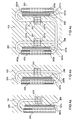
- the figure 1 an electronic card in section surmounted by a heat sink without the device according to the invention.
- the electronic card 100 comprises a printed circuit 101 and several components 111, 112, 113 constituting hot spots.
- a heat sink 103 which in the example is specially adapted to the electronic card 100, is mounted above the components 111, 112, 113 so as to collect the heat dissipated by them.
- the heat sink 103 comes into contact with the slides 107a, 107b of the frame 109 in which the card 100 is inserted.
- the figure 2 an electronic card provided with the cooling device according to the invention.
- the device comprises a first heat conduction part 201, a second heat conduction part 203, a heat pipe 205 connecting the two heat conduction parts 201, 203, and clamping means 207.
- the first heat conduction part 201 is contiguous with the side of the heat sink 103 which is opposite the side in contact with the components 111, 112, 113 of the card 100.
- the first heat conduction part 201 is kept under pressure on the heat sink 103, near a hot spot, for example, above a component 211.
- the first heat conduction part 201 may, for example, be a metal bar screwed on the heat sink 103 or maintained by a spring effect device. The tightening must ensure a good thermal conduction between the conduction part 201 and the hot spot.
- the first heat conduction part 201 ' is placed directly in contact with the hot spot - for example, on a component 213 -.
- a heat conduction part 201, 203 may be a block, for example a solid metal parallelepiped 201, 203, that this part is a bar 201 fixed on the heat sink 103 or that it takes the form of a hood 201 'shutter an opening formed in the heat sink 103, the hood 201 'then being in direct contact with the hot spot 213.
- the choice between the use of a bar 201 or a hood 201' is carried out in particular according to the shape and the uniformity of the thermal density of the area to be cooled. In the case of an isolated component requiring a specific cooling path, the cover 201 ', in direct contact with the component, will be preferred.
- the heat captured by the first heat conduction part 201 must then be evacuated; the heat pipe 205 is used for this purpose.
- the heat pipe 205 may be a pipe of rectangular curved section for connecting the two heat conduction parts 201, 203.
- the heat pipe 205 is curved in a plane parallel to the heat sink 103, the long side of the pipe being positioned in a plane orthogonal to the curvature plane.
- the height H 1 between the upper face of the heat sink 103 and the lower face of the slide corresponding to the slot located above the electronic card 100 may be approximately equal to 5 mm, the height H 2 between the face lower the heat sink 103 and the lower face of the same slide being, for example, equal to 10mm.
- the heat pipe 205 makes it possible to drive the calories coming from the hot point 211 and transmitted to the first heat conduction part 201 to the second heat conduction part 203.
- the first heat conduction part 201, the heat pipe 205, and the second heat conduction part 203 are one and the same piece of shaped material.
- the second heat conduction part 203 is placed at an edge of the electronic card 200, close to a cold wall, in the example the frame 109, so that by pressing the second conduction part thermal 203 against the cold side wall 109, a heat exchange surface is created.
- the heat pipe 205 has, depending on the material in which it is made, its length and the shape that has been given to it, a certain flexibility that gives mobility to the second heat conduction part 203.
- the heat pipe 205 must benefit from a freedom of movement, and therefore should not, for example, be fully embedded in the heat sink 103.
- the second heat conduction part 203 can move slightly in a plane parallel to the heat sink 103 and according to an axis substantially connecting the two pieces of conductions 201, 203.
- the clamping means 207 are arranged against the side of the second conduction piece 203 which is opposite the cold wall 109.
- the clamping means 207 comprise for example a expandable system type "wedge lock", this type of system comprising two movable parts relative to each other, these two parts apart for example by turning a screw of ser rage.
- a first part 207a of the wedge lock is attached to the second heat conduction part 203 and a second part 207b of the wedge lock is held stationary relative to the heat sink 103, for example via a stop 208.
- the stop 208 can be formed on the heat sink 103 to retain the means of clamping 207 and guide the second heat conduction part 203 in the desired axis of displacement.
- the mobility of the second conduction part 203 associated with the clamping system 207 allows the device according to the invention to take at least two different positions: an open position in which the two moving parts 207a, 207b of the clamping means 207 are brought together, the second conduction part 203 then being separated from the cold wall 109, and a locked position in which the two parts 207a, 207b of the wedge lock are spaced, the second conduction part 203 then being pressed against the cold wall 109 to complete the path thermal evacuation.
- a protuberance 209 may be formed in the heat sink 103 at the ends close to the slides 107a, 107b to prevent the card 200 from being moved, by counter-thrusting effect, in the direction opposite to the direction of movement of the first part mobile 207a of the wedge lock; the protrusion 209 thus makes it possible to block the electronic card during the locking of the clamping means 207.
- the first heat conduction part 201, 201 ' can be integrated with the heat sink 103.
- the first half 207a of the wedge lock 207 can be integrated into the second piece of thermal conduction 203 to reduce the number of moving parts and facilitate the mounting of the device.
- the Figures 3a, 3b, 3c , 3d have several possible configurations of association between thermal conductor bars and a heat pipe of the device according to the invention.
- the first and second heat conducting parts 201, 203 are metal bars seen from above.
- the figure 3a has a first configuration in which the two bars 203 are connected by a heat pipe 205 of short length shaped U and parallel to the plane of the heat sink 103.
- Each end of the heat pipe 205 is embedded in a bar 201, 203, so as to leave, thanks to the elasticity of the heat pipe 205, a certain mobility to the bar 203 attached to the wedge lock 207 and the heat pipe 205, as indicated by the arrow 301.
- a small empty space can be reserved between the heat pipe 205 and each of the bars 201, 203, at the ends 201, 203a of the bars, to leave a play heat pipe 205.
- This configuration has the advantage of simplicity.
- the figure 3b has a second configuration in which the heat pipe 205 is longer than in the first configuration.
- This configuration has the advantage of greater flexibility of the heat pipe 205, thanks to its greater length.
- the figure 3c has a third configuration in which the heat pipe 205 passes through each of the bars 201, 203.
- the heat pipe 205 connects the first end 201a of the first bar 201 to the second end 203b of the second bar 203 and the first end 203a of the second bar 203 at the second end 201b of the first bar 201, said bars 201, 203 being traversed by the heat pipe 205 so as to optimize the heat exchange.
- This configuration has the particular advantage of being more independent of gravity or of another acceleration force than the first and the second configuration, and thus of facilitating the displacement of the drops of fluid contained in the heat pipe 205 to an evaporator .(hotspot). This configuration can be useful when the card is subjected to accelerations, for example if it is embedded in an aircraft.
- FIGS. 4a, 4b, 4c , 4d have several possible configurations of association between covers and heat conducting bars and a heat pipe of the device according to the invention.
- the figure 4a has a fourth configuration in which the first conduction part is a cover 201 'and the second conduction part is a bar 203. One end of the cover 201' and one end of the bar 203 are connected by a heat pipe 205. As the first configuration illustrated in figure 3a this configuration has the advantage of simplicity.
- the figure 4b has a fifth configuration in which the first conduction part is a hood 201 'and the second conduction part is a bar 203.
- the figure 4c has a sixth configuration comprising two covers 201 ', 201 ", two bars 203, 203' Each bar 203, 203 'is placed against a cold wall and each cover 201', 201" is placed on a hot spot.
- the first end 201'a of the first cover 201 ' is connected to the first end 203a of the first bar 203, the second end 203b of the first bar being connected to the second end 201 "b of the second cover 201", the first end 201 " a being connected to the first end 203a 'of the second bar 203', the second end 203b 'of the second bar 203' being connected to the second end 201b 'of the first cover 201'
- This fifth configuration makes it possible to dispense with the problems of acceleration or gravity, especially when the direction of acceleration or gravity is perpendicular to the slides and is in the plane of the heat sink 103: if the cooling to the cold wall against which is placed the first bar 203 is thwarted by the acceleration, it will be strengthened towards the cold wall against which is placed the second bar 203 ', and vice versa.
- the device according to the invention is well adapted to the new design standards of modular computers, which tend to increase the available distance between two slots (that is to say two locations) consecutive card.
- the device according to the invention can advantageously be used within the framework of the VPX standard (VITA-46), VITA being the acronym for VME INTERNATIONAL TRADE ASSOCIATION.
- VITA-46 is the name of a standard developed by VITA.
Landscapes
- Engineering & Computer Science (AREA)
- Computer Hardware Design (AREA)
- General Engineering & Computer Science (AREA)
- Physics & Mathematics (AREA)
- Thermal Sciences (AREA)
- Microelectronics & Electronic Packaging (AREA)
- Cooling Or The Like Of Electrical Apparatus (AREA)
- Cooling Or The Like Of Semiconductors Or Solid State Devices (AREA)
Applications Claiming Priority (1)
| Application Number | Priority Date | Filing Date | Title |
|---|---|---|---|
| FR1000525A FR2956280A1 (fr) | 2010-02-09 | 2010-02-09 | Dispositif auxiliaire d'evacuation par conduction de la chaleur produite par une carte electronique |
Publications (2)
| Publication Number | Publication Date |
|---|---|
| EP2355643A1 true EP2355643A1 (de) | 2011-08-10 |
| EP2355643B1 EP2355643B1 (de) | 2012-11-28 |
Family
ID=42299643
Family Applications (1)
| Application Number | Title | Priority Date | Filing Date |
|---|---|---|---|
| EP11153868A Active EP2355643B1 (de) | 2010-02-09 | 2011-02-09 | Hilfsvorrichtung zur Ableitung durch Wärmeleitung, die über eine elektronische Karte gesteuert wird |
Country Status (4)
| Country | Link |
|---|---|
| US (1) | US8570749B2 (de) |
| EP (1) | EP2355643B1 (de) |
| CA (1) | CA2730881A1 (de) |
| FR (1) | FR2956280A1 (de) |
Cited By (1)
| Publication number | Priority date | Publication date | Assignee | Title |
|---|---|---|---|---|
| FR3060939A1 (fr) * | 2016-12-15 | 2018-06-22 | Thales | Systeme de drainage thermique |
Families Citing this family (18)
| Publication number | Priority date | Publication date | Assignee | Title |
|---|---|---|---|---|
| US8913391B2 (en) * | 2012-01-30 | 2014-12-16 | Alcatel Lucent | Board-level heat transfer apparatus for communication platforms |
| US9036353B2 (en) | 2012-11-26 | 2015-05-19 | Northrop Grumman Systems Corporation | Flexible thermal interface for electronics |
| US9253925B1 (en) * | 2013-01-11 | 2016-02-02 | L-3 Communications Corp. | Panel for enhancing thermal conduction in an electronic assembly |
| US9144178B2 (en) | 2013-03-01 | 2015-09-22 | International Business Machines Corporation | Selective clamping of electronics card to coolant-cooled structure |
| US10928139B1 (en) | 2013-08-16 | 2021-02-23 | Advanced Cooling Technologies, Inc. | Assembly and process for heat transfer with three surfaces |
| KR102186842B1 (ko) * | 2014-05-26 | 2020-12-04 | 엘지전자 주식회사 | 이동 단말기 |
| CA2954439A1 (en) * | 2014-07-08 | 2016-01-14 | Adc Technologies Inc. | Robust redundant-capable leak-resistant cooled enclosure wall |
| US9370090B2 (en) * | 2014-09-29 | 2016-06-14 | General Electric Company | Circuit card assembly and method of manufacturing thereof |
| US9706668B2 (en) * | 2014-10-24 | 2017-07-11 | Samsung Electro-Mechanics Co., Ltd. | Printed circuit board, electronic module and method of manufacturing the same |
| US10225953B2 (en) | 2014-10-31 | 2019-03-05 | Thermal Corp. | Vehicle thermal management system |
| US9965003B2 (en) * | 2015-07-09 | 2018-05-08 | Htc Corporation | Electronic assembly and electronic device |
| US9835382B2 (en) * | 2015-09-16 | 2017-12-05 | Acer Incorporated | Thermal dissipation module |
| US9668335B1 (en) * | 2016-02-22 | 2017-05-30 | Arris Enterprises Llc | Heat sink fastener and corresponding systems and methods |
| CN205909724U (zh) * | 2016-06-27 | 2017-01-25 | 富瑞精密组件(昆山)有限公司 | 组合式热管及应用该组合式热管的电子装置 |
| US10602635B2 (en) * | 2018-01-19 | 2020-03-24 | Lockheed Martin Corporation | Two-phase fluid-actuated cooling device, system, and method |
| DE102021203625A1 (de) | 2021-04-13 | 2022-10-13 | Robert Bosch Gesellschaft mit beschränkter Haftung | Elektronikbaugruppe eines Kraftfahrzeugs |
| CN113286466B (zh) * | 2021-05-21 | 2022-05-31 | 中国电子科技集团公司第二十九研究所 | 一种低剖面电子模块的一体化锁紧、导热结构 |
| US12604437B2 (en) | 2023-08-21 | 2026-04-14 | Rockwell Collins, Inc. | Compact modular hybrid heat exchanger (CMH2X) |
Citations (5)
| Publication number | Priority date | Publication date | Assignee | Title |
|---|---|---|---|---|
| US20060044760A1 (en) * | 2004-08-31 | 2006-03-02 | Debabrata Pal | Integrated heat removal and vibration damping for avionic equipment |
| FR2907634A1 (fr) * | 2006-10-24 | 2008-04-25 | Thales Sa | Boitier electrique a cartes electroniques comportant des caloducs |
| EP2061296A1 (de) * | 2007-11-16 | 2009-05-20 | GE Aviation Systems LLC | Leitungsgekühlte Leiterplattenanordnung |
| FR2925254A1 (fr) | 2007-12-18 | 2009-06-19 | Thales Sa | Dispositif de refroidissement d'une carte electronique par conduction a l'aide de caloducs,et procede de fabrication correspondant. |
| FR2929070A1 (fr) | 2008-03-18 | 2009-09-25 | Kontron Modular Computers Sa | Dispositif de prechauffage d'un composant refroidi par conduction et/ou par convection |
Family Cites Families (11)
| Publication number | Priority date | Publication date | Assignee | Title |
|---|---|---|---|---|
| US4867235A (en) * | 1986-10-20 | 1989-09-19 | Westinghouse Electric Corp. | Composite heat transfer means |
| DE4028003A1 (de) * | 1990-09-04 | 1992-03-05 | Messerschmitt Boelkow Blohm | Klemmelement zur halterung von elektronik-karten |
| US6765798B1 (en) * | 2003-06-19 | 2004-07-20 | Curtiss-Wright Controls, Inc. | Electronic thermal management utilizing device with deflectable, two-leg conductive member; and with elastic, thermally-conductive material there between |
| US20060109631A1 (en) * | 2004-11-02 | 2006-05-25 | Data Device Corporation | Method and apparatus for connecting circuit cards employing a cooling technique to achieve desired temperature thresholds and card alignment |
| US7345877B2 (en) * | 2005-01-06 | 2008-03-18 | The Boeing Company | Cooling apparatus, system, and associated method |
| US8174828B2 (en) * | 2006-02-06 | 2012-05-08 | Parker-Hannifin Corporation | Narrow gap spray cooling in a globally cooled enclosure |
| US7349221B2 (en) * | 2006-07-20 | 2008-03-25 | Honeywell International Inc. | Device for increased thermal conductivity between a printed wiring assembly and a chassis |
| US8223494B2 (en) * | 2007-12-31 | 2012-07-17 | General Electric Company | Conduction cooled circuit board assembly |
| US7787249B2 (en) * | 2009-02-03 | 2010-08-31 | Honeywell International Inc. | Systems and methods for printed board assembly isolated heat exchange |
| US8223497B2 (en) * | 2009-09-10 | 2012-07-17 | Honeywell International Inc. | Thermal bridge extensions for a module-chassis interface |
| WO2011119926A2 (en) * | 2010-03-25 | 2011-09-29 | Porreca Paul J | Conduction-cooled apparatus and methods of forming said apparatus |
-
2010
- 2010-02-09 FR FR1000525A patent/FR2956280A1/fr not_active Withdrawn
-
2011
- 2011-02-08 US US13/022,733 patent/US8570749B2/en active Active
- 2011-02-08 CA CA2730881A patent/CA2730881A1/en not_active Abandoned
- 2011-02-09 EP EP11153868A patent/EP2355643B1/de active Active
Patent Citations (5)
| Publication number | Priority date | Publication date | Assignee | Title |
|---|---|---|---|---|
| US20060044760A1 (en) * | 2004-08-31 | 2006-03-02 | Debabrata Pal | Integrated heat removal and vibration damping for avionic equipment |
| FR2907634A1 (fr) * | 2006-10-24 | 2008-04-25 | Thales Sa | Boitier electrique a cartes electroniques comportant des caloducs |
| EP2061296A1 (de) * | 2007-11-16 | 2009-05-20 | GE Aviation Systems LLC | Leitungsgekühlte Leiterplattenanordnung |
| FR2925254A1 (fr) | 2007-12-18 | 2009-06-19 | Thales Sa | Dispositif de refroidissement d'une carte electronique par conduction a l'aide de caloducs,et procede de fabrication correspondant. |
| FR2929070A1 (fr) | 2008-03-18 | 2009-09-25 | Kontron Modular Computers Sa | Dispositif de prechauffage d'un composant refroidi par conduction et/ou par convection |
Cited By (1)
| Publication number | Priority date | Publication date | Assignee | Title |
|---|---|---|---|---|
| FR3060939A1 (fr) * | 2016-12-15 | 2018-06-22 | Thales | Systeme de drainage thermique |
Also Published As
| Publication number | Publication date |
|---|---|
| FR2956280A1 (fr) | 2011-08-12 |
| CA2730881A1 (en) | 2011-08-09 |
| US20120069526A1 (en) | 2012-03-22 |
| US8570749B2 (en) | 2013-10-29 |
| EP2355643B1 (de) | 2012-11-28 |
Similar Documents
| Publication | Publication Date | Title |
|---|---|---|
| EP2355643B1 (de) | Hilfsvorrichtung zur Ableitung durch Wärmeleitung, die über eine elektronische Karte gesteuert wird | |
| EP2223583B1 (de) | Vorrichtung zur kühlung einer elektronikkarte mittels leitung mit heizrohren und entsprechendes herstellungsverfahren | |
| EP2653021B1 (de) | Kühlung einer elektronischen vorrichtung | |
| EP2770809B1 (de) | Elektronische Karte | |
| CA2393069A1 (fr) | Coffre pour convertisseur de puissance | |
| WO2010118971A1 (fr) | Boîtier pour carte électronique embarquée | |
| WO2015155426A1 (fr) | Armoire electrique destinee aux applications en milieux a risques | |
| FR2870667A1 (fr) | Dispositif de conversion de puissance | |
| US4660132A (en) | Cooling device for mounting and protecting an optical element | |
| EP2362720B1 (de) | Elektronisches module und elektronische Anordnung umfassend dieses Modul | |
| FR2689361A1 (fr) | Dispositif de refroidissement de circuit inductif. | |
| EP2861928B1 (de) | Temperaturregelungsvorrichtung | |
| EP4324311A1 (de) | Modulare elektronische vorrichtung mit optimierter kühlung | |
| EP3549164B1 (de) | Vorrichtung zur beseitigung von wärme | |
| WO2013135595A1 (fr) | Calculateur et radiateur pour ce calculateur | |
| EP4064807B1 (de) | Kühlvorrichtung für elektronische komponenten | |
| FR2636490A1 (fr) | Dispositif de liaison mecanique et thermique pour carte de circuits electroniques | |
| WO2024002586A1 (fr) | Système de plaquage d'un serveur sur un bloc métallique | |
| FR3167032A1 (fr) | Boîtier étanche configuré pour recevoir un ou plusieurs composants | |
| FR2942366A1 (fr) | Capot de protection pour disque dur extractible | |
| FR2965141A1 (fr) | Carte electronique a refroidissement diphasique, equipement electronique incorporant une telle carte et aeronef incorporant un tel equipement | |
| FR3062711A1 (fr) | Dispositif de chauffage electrique de fluide pour vehicule automobile | |
| FR2641663A1 (fr) | Boitier pour composants hybrides | |
| FR2683029A1 (fr) | Dispositif de regulation de temperature pour boitier. |
Legal Events
| Date | Code | Title | Description |
|---|---|---|---|
| PUAI | Public reference made under article 153(3) epc to a published international application that has entered the european phase |
Free format text: ORIGINAL CODE: 0009012 |
|
| AK | Designated contracting states |
Kind code of ref document: A1 Designated state(s): AL AT BE BG CH CY CZ DE DK EE ES FI FR GB GR HR HU IE IS IT LI LT LU LV MC MK MT NL NO PL PT RO RS SE SI SK SM TR |
|
| AX | Request for extension of the european patent |
Extension state: BA ME |
|
| 17P | Request for examination filed |
Effective date: 20120214 |
|
| GRAP | Despatch of communication of intention to grant a patent |
Free format text: ORIGINAL CODE: EPIDOSNIGR1 |
|
| GRAS | Grant fee paid |
Free format text: ORIGINAL CODE: EPIDOSNIGR3 |
|
| GRAA | (expected) grant |
Free format text: ORIGINAL CODE: 0009210 |
|
| AK | Designated contracting states |
Kind code of ref document: B1 Designated state(s): AL AT BE BG CH CY CZ DE DK EE ES FI FR GB GR HR HU IE IS IT LI LT LU LV MC MK MT NL NO PL PT RO RS SE SI SK SM TR |
|
| REG | Reference to a national code |
Ref country code: GB Ref legal event code: FG4D Free format text: NOT ENGLISH |
|
| REG | Reference to a national code |
Ref country code: CH Ref legal event code: EP |
|
| REG | Reference to a national code |
Ref country code: AT Ref legal event code: REF Ref document number: 586738 Country of ref document: AT Kind code of ref document: T Effective date: 20121215 |
|
| REG | Reference to a national code |
Ref country code: IE Ref legal event code: FG4D Free format text: LANGUAGE OF EP DOCUMENT: FRENCH |
|
| REG | Reference to a national code |
Ref country code: DE Ref legal event code: R096 Ref document number: 602011000504 Country of ref document: DE Effective date: 20130124 |
|
| REG | Reference to a national code |
Ref country code: AT Ref legal event code: MK05 Ref document number: 586738 Country of ref document: AT Kind code of ref document: T Effective date: 20121128 |
|
| REG | Reference to a national code |
Ref country code: NL Ref legal event code: VDEP Effective date: 20121128 |
|
| REG | Reference to a national code |
Ref country code: LT Ref legal event code: MG4D |
|
| PG25 | Lapsed in a contracting state [announced via postgrant information from national office to epo] |
Ref country code: SE Free format text: LAPSE BECAUSE OF FAILURE TO SUBMIT A TRANSLATION OF THE DESCRIPTION OR TO PAY THE FEE WITHIN THE PRESCRIBED TIME-LIMIT Effective date: 20121128 Ref country code: FI Free format text: LAPSE BECAUSE OF FAILURE TO SUBMIT A TRANSLATION OF THE DESCRIPTION OR TO PAY THE FEE WITHIN THE PRESCRIBED TIME-LIMIT Effective date: 20121128 Ref country code: NO Free format text: LAPSE BECAUSE OF FAILURE TO SUBMIT A TRANSLATION OF THE DESCRIPTION OR TO PAY THE FEE WITHIN THE PRESCRIBED TIME-LIMIT Effective date: 20130228 Ref country code: LT Free format text: LAPSE BECAUSE OF FAILURE TO SUBMIT A TRANSLATION OF THE DESCRIPTION OR TO PAY THE FEE WITHIN THE PRESCRIBED TIME-LIMIT Effective date: 20121128 Ref country code: ES Free format text: LAPSE BECAUSE OF FAILURE TO SUBMIT A TRANSLATION OF THE DESCRIPTION OR TO PAY THE FEE WITHIN THE PRESCRIBED TIME-LIMIT Effective date: 20130311 |
|
| PG25 | Lapsed in a contracting state [announced via postgrant information from national office to epo] |
Ref country code: PT Free format text: LAPSE BECAUSE OF FAILURE TO SUBMIT A TRANSLATION OF THE DESCRIPTION OR TO PAY THE FEE WITHIN THE PRESCRIBED TIME-LIMIT Effective date: 20130328 Ref country code: PL Free format text: LAPSE BECAUSE OF FAILURE TO SUBMIT A TRANSLATION OF THE DESCRIPTION OR TO PAY THE FEE WITHIN THE PRESCRIBED TIME-LIMIT Effective date: 20121128 Ref country code: GR Free format text: LAPSE BECAUSE OF FAILURE TO SUBMIT A TRANSLATION OF THE DESCRIPTION OR TO PAY THE FEE WITHIN THE PRESCRIBED TIME-LIMIT Effective date: 20130301 Ref country code: SI Free format text: LAPSE BECAUSE OF FAILURE TO SUBMIT A TRANSLATION OF THE DESCRIPTION OR TO PAY THE FEE WITHIN THE PRESCRIBED TIME-LIMIT Effective date: 20121128 Ref country code: LV Free format text: LAPSE BECAUSE OF FAILURE TO SUBMIT A TRANSLATION OF THE DESCRIPTION OR TO PAY THE FEE WITHIN THE PRESCRIBED TIME-LIMIT Effective date: 20121128 |
|
| PG25 | Lapsed in a contracting state [announced via postgrant information from national office to epo] |
Ref country code: AT Free format text: LAPSE BECAUSE OF FAILURE TO SUBMIT A TRANSLATION OF THE DESCRIPTION OR TO PAY THE FEE WITHIN THE PRESCRIBED TIME-LIMIT Effective date: 20121128 |
|
| PG25 | Lapsed in a contracting state [announced via postgrant information from national office to epo] |
Ref country code: EE Free format text: LAPSE BECAUSE OF FAILURE TO SUBMIT A TRANSLATION OF THE DESCRIPTION OR TO PAY THE FEE WITHIN THE PRESCRIBED TIME-LIMIT Effective date: 20121128 Ref country code: DK Free format text: LAPSE BECAUSE OF FAILURE TO SUBMIT A TRANSLATION OF THE DESCRIPTION OR TO PAY THE FEE WITHIN THE PRESCRIBED TIME-LIMIT Effective date: 20121128 Ref country code: RS Free format text: LAPSE BECAUSE OF FAILURE TO SUBMIT A TRANSLATION OF THE DESCRIPTION OR TO PAY THE FEE WITHIN THE PRESCRIBED TIME-LIMIT Effective date: 20121128 Ref country code: SK Free format text: LAPSE BECAUSE OF FAILURE TO SUBMIT A TRANSLATION OF THE DESCRIPTION OR TO PAY THE FEE WITHIN THE PRESCRIBED TIME-LIMIT Effective date: 20121128 Ref country code: CZ Free format text: LAPSE BECAUSE OF FAILURE TO SUBMIT A TRANSLATION OF THE DESCRIPTION OR TO PAY THE FEE WITHIN THE PRESCRIBED TIME-LIMIT Effective date: 20121128 Ref country code: BG Free format text: LAPSE BECAUSE OF FAILURE TO SUBMIT A TRANSLATION OF THE DESCRIPTION OR TO PAY THE FEE WITHIN THE PRESCRIBED TIME-LIMIT Effective date: 20130228 |
|
| PG25 | Lapsed in a contracting state [announced via postgrant information from national office to epo] |
Ref country code: RO Free format text: LAPSE BECAUSE OF FAILURE TO SUBMIT A TRANSLATION OF THE DESCRIPTION OR TO PAY THE FEE WITHIN THE PRESCRIBED TIME-LIMIT Effective date: 20121128 Ref country code: NL Free format text: LAPSE BECAUSE OF FAILURE TO SUBMIT A TRANSLATION OF THE DESCRIPTION OR TO PAY THE FEE WITHIN THE PRESCRIBED TIME-LIMIT Effective date: 20121128 |
|
| BERE | Be: lapsed |
Owner name: KONTRON MODULAR COMPUTERS S.A. Effective date: 20130228 |
|
| PG25 | Lapsed in a contracting state [announced via postgrant information from national office to epo] |
Ref country code: MC Free format text: LAPSE BECAUSE OF NON-PAYMENT OF DUE FEES Effective date: 20130228 |
|
| PLBE | No opposition filed within time limit |
Free format text: ORIGINAL CODE: 0009261 |
|
| STAA | Information on the status of an ep patent application or granted ep patent |
Free format text: STATUS: NO OPPOSITION FILED WITHIN TIME LIMIT |
|
| 26N | No opposition filed |
Effective date: 20130829 |
|
| PG25 | Lapsed in a contracting state [announced via postgrant information from national office to epo] |
Ref country code: CY Free format text: LAPSE BECAUSE OF FAILURE TO SUBMIT A TRANSLATION OF THE DESCRIPTION OR TO PAY THE FEE WITHIN THE PRESCRIBED TIME-LIMIT Effective date: 20121128 |
|
| REG | Reference to a national code |
Ref country code: IE Ref legal event code: MM4A |
|
| REG | Reference to a national code |
Ref country code: DE Ref legal event code: R097 Ref document number: 602011000504 Country of ref document: DE Effective date: 20130829 |
|
| PG25 | Lapsed in a contracting state [announced via postgrant information from national office to epo] |
Ref country code: IE Free format text: LAPSE BECAUSE OF NON-PAYMENT OF DUE FEES Effective date: 20130209 Ref country code: BE Free format text: LAPSE BECAUSE OF NON-PAYMENT OF DUE FEES Effective date: 20130228 Ref country code: HR Free format text: LAPSE BECAUSE OF FAILURE TO SUBMIT A TRANSLATION OF THE DESCRIPTION OR TO PAY THE FEE WITHIN THE PRESCRIBED TIME-LIMIT Effective date: 20130731 Ref country code: AL Free format text: LAPSE BECAUSE OF FAILURE TO SUBMIT A TRANSLATION OF THE DESCRIPTION OR TO PAY THE FEE WITHIN THE PRESCRIBED TIME-LIMIT Effective date: 20121128 |
|
| PG25 | Lapsed in a contracting state [announced via postgrant information from national office to epo] |
Ref country code: MT Free format text: LAPSE BECAUSE OF FAILURE TO SUBMIT A TRANSLATION OF THE DESCRIPTION OR TO PAY THE FEE WITHIN THE PRESCRIBED TIME-LIMIT Effective date: 20121128 |
|
| REG | Reference to a national code |
Ref country code: CH Ref legal event code: PL |
|
| PG25 | Lapsed in a contracting state [announced via postgrant information from national office to epo] |
Ref country code: LI Free format text: LAPSE BECAUSE OF NON-PAYMENT OF DUE FEES Effective date: 20140228 Ref country code: CH Free format text: LAPSE BECAUSE OF NON-PAYMENT OF DUE FEES Effective date: 20140228 |
|
| PG25 | Lapsed in a contracting state [announced via postgrant information from national office to epo] |
Ref country code: SM Free format text: LAPSE BECAUSE OF FAILURE TO SUBMIT A TRANSLATION OF THE DESCRIPTION OR TO PAY THE FEE WITHIN THE PRESCRIBED TIME-LIMIT Effective date: 20121128 |
|
| PG25 | Lapsed in a contracting state [announced via postgrant information from national office to epo] |
Ref country code: TR Free format text: LAPSE BECAUSE OF FAILURE TO SUBMIT A TRANSLATION OF THE DESCRIPTION OR TO PAY THE FEE WITHIN THE PRESCRIBED TIME-LIMIT Effective date: 20121128 |
|
| PG25 | Lapsed in a contracting state [announced via postgrant information from national office to epo] |
Ref country code: MK Free format text: LAPSE BECAUSE OF FAILURE TO SUBMIT A TRANSLATION OF THE DESCRIPTION OR TO PAY THE FEE WITHIN THE PRESCRIBED TIME-LIMIT Effective date: 20121128 Ref country code: LU Free format text: LAPSE BECAUSE OF NON-PAYMENT OF DUE FEES Effective date: 20130209 Ref country code: HU Free format text: LAPSE BECAUSE OF FAILURE TO SUBMIT A TRANSLATION OF THE DESCRIPTION OR TO PAY THE FEE WITHIN THE PRESCRIBED TIME-LIMIT; INVALID AB INITIO Effective date: 20110209 |
|
| REG | Reference to a national code |
Ref country code: FR Ref legal event code: PLFP Year of fee payment: 6 |
|
| PG25 | Lapsed in a contracting state [announced via postgrant information from national office to epo] |
Ref country code: IS Free format text: LAPSE BECAUSE OF FAILURE TO SUBMIT A TRANSLATION OF THE DESCRIPTION OR TO PAY THE FEE WITHIN THE PRESCRIBED TIME-LIMIT Effective date: 20121128 |
|
| REG | Reference to a national code |
Ref country code: FR Ref legal event code: PLFP Year of fee payment: 7 |
|
| REG | Reference to a national code |
Ref country code: FR Ref legal event code: PLFP Year of fee payment: 8 |
|
| PGFP | Annual fee paid to national office [announced via postgrant information from national office to epo] |
Ref country code: IT Payment date: 20210126 Year of fee payment: 11 |
|
| PG25 | Lapsed in a contracting state [announced via postgrant information from national office to epo] |
Ref country code: IT Free format text: LAPSE BECAUSE OF NON-PAYMENT OF DUE FEES Effective date: 20220209 |
|
| PGFP | Annual fee paid to national office [announced via postgrant information from national office to epo] |
Ref country code: GB Payment date: 20260119 Year of fee payment: 16 |
|
| PGFP | Annual fee paid to national office [announced via postgrant information from national office to epo] |
Ref country code: DE Payment date: 20260114 Year of fee payment: 16 |
|
| PGFP | Annual fee paid to national office [announced via postgrant information from national office to epo] |
Ref country code: FR Payment date: 20260121 Year of fee payment: 16 |