EP4064807B1 - Kühlvorrichtung für elektronische komponenten - Google Patents
Kühlvorrichtung für elektronische komponenten Download PDFInfo
- Publication number
- EP4064807B1 EP4064807B1 EP22164351.3A EP22164351A EP4064807B1 EP 4064807 B1 EP4064807 B1 EP 4064807B1 EP 22164351 A EP22164351 A EP 22164351A EP 4064807 B1 EP4064807 B1 EP 4064807B1
- Authority
- EP
- European Patent Office
- Prior art keywords
- locking
- frame
- cooling device
- holding
- plate
- Prior art date
- Legal status (The legal status is an assumption and is not a legal conclusion. Google has not performed a legal analysis and makes no representation as to the accuracy of the status listed.)
- Active
Links
Images



Classifications
-
- H—ELECTRICITY
- H05—ELECTRIC TECHNIQUES NOT OTHERWISE PROVIDED FOR
- H05K—PRINTED CIRCUITS; CASINGS OR CONSTRUCTIONAL DETAILS OF ELECTRIC APPARATUS; MANUFACTURE OF ASSEMBLAGES OF ELECTRICAL COMPONENTS
- H05K7/00—Constructional details common to different types of electric apparatus
- H05K7/14—Mounting supporting structure in casing or on frame or rack
- H05K7/1401—Mounting supporting structure in casing or on frame or rack comprising clamping or extracting means
- H05K7/1402—Mounting supporting structure in casing or on frame or rack comprising clamping or extracting means for securing or extracting printed circuit boards
- H05K7/1404—Mounting supporting structure in casing or on frame or rack comprising clamping or extracting means for securing or extracting printed circuit boards by edge clamping, e.g. wedges
-
- H—ELECTRICITY
- H05—ELECTRIC TECHNIQUES NOT OTHERWISE PROVIDED FOR
- H05K—PRINTED CIRCUITS; CASINGS OR CONSTRUCTIONAL DETAILS OF ELECTRIC APPARATUS; MANUFACTURE OF ASSEMBLAGES OF ELECTRICAL COMPONENTS
- H05K7/00—Constructional details common to different types of electric apparatus
- H05K7/14—Mounting supporting structure in casing or on frame or rack
- H05K7/1422—Printed circuit boards receptacles, e.g. stacked structures, electronic circuit modules or box like frames
- H05K7/1424—Card cages
-
- H—ELECTRICITY
- H05—ELECTRIC TECHNIQUES NOT OTHERWISE PROVIDED FOR
- H05K—PRINTED CIRCUITS; CASINGS OR CONSTRUCTIONAL DETAILS OF ELECTRIC APPARATUS; MANUFACTURE OF ASSEMBLAGES OF ELECTRICAL COMPONENTS
- H05K7/00—Constructional details common to different types of electric apparatus
- H05K7/20—Modifications to facilitate cooling, ventilating, or heating
- H05K7/2039—Modifications to facilitate cooling, ventilating, or heating characterised by the heat transfer by conduction from the heat generating element to a dissipating body
- H05K7/20409—Outer radiating structures on heat dissipating housings, e.g. fins integrated with the housing
- H05K7/20418—Outer radiating structures on heat dissipating housings, e.g. fins integrated with the housing the radiating structures being additional and fastened onto the housing
-
- H—ELECTRICITY
- H05—ELECTRIC TECHNIQUES NOT OTHERWISE PROVIDED FOR
- H05K—PRINTED CIRCUITS; CASINGS OR CONSTRUCTIONAL DETAILS OF ELECTRIC APPARATUS; MANUFACTURE OF ASSEMBLAGES OF ELECTRICAL COMPONENTS
- H05K7/00—Constructional details common to different types of electric apparatus
- H05K7/20—Modifications to facilitate cooling, ventilating, or heating
- H05K7/20536—Modifications to facilitate cooling, ventilating, or heating for racks or cabinets of standardised dimensions, e.g. electronic racks for aircraft or telecommunication equipment
- H05K7/20545—Natural convection of gaseous coolant; Heat transfer by conduction from electronic boards
-
- F—MECHANICAL ENGINEERING; LIGHTING; HEATING; WEAPONS; BLASTING
- F16—ENGINEERING ELEMENTS AND UNITS; GENERAL MEASURES FOR PRODUCING AND MAINTAINING EFFECTIVE FUNCTIONING OF MACHINES OR INSTALLATIONS; THERMAL INSULATION IN GENERAL
- F16B—DEVICES FOR FASTENING OR SECURING CONSTRUCTIONAL ELEMENTS OR MACHINE PARTS TOGETHER, e.g. NAILS, BOLTS, CIRCLIPS, CLAMPS, CLIPS OR WEDGES; JOINTS OR JOINTING
- F16B2/00—Friction-grip releasable fastenings
- F16B2/02—Clamps, i.e. with gripping action effected by positive means other than the inherent resistance to deformation of the material of the fastening
- F16B2/06—Clamps, i.e. with gripping action effected by positive means other than the inherent resistance to deformation of the material of the fastening external, i.e. with contracting action
- F16B2/065—Clamps, i.e. with gripping action effected by positive means other than the inherent resistance to deformation of the material of the fastening external, i.e. with contracting action using screw-thread elements
Definitions
- Such electronic components are for example used in the field of transport and the proper cooling of these components is generally critical to ensure the proper operation of a vehicle.
- cooling devices In the field of rail transport, cooling devices are known, for example, comprising a casing accommodating plates of electronic components. Such plates of electronic components generate heat which it is essential to evacuate from the case.
- One of the aims of the invention is then to propose a cooling device that is easy to install and inexpensive.
- the subject of the invention is a cooling device according to claim 1.
- a cooling device comprising a holding element which can be brought into its holding configuration by simple bending is particularly advantageous because of the simplicity of bringing the holding element from its release configuration to its holding configuration, and vice versa.
- Such a device cooling is also particularly inexpensive to produce, especially because of the small number of components it comprises.
- the cooling device comprises one or more of the characteristics of claims 2 to 7, taken separately or in any technically possible combination.
- a vehicle (not shown) comprises an electronic system 10.
- the vehicle is for example a railway vehicle such as a high-speed train, a regional train, a tramway or a metro.
- the vehicle is a road vehicle such as a bus.
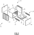
- the electronic system 10 comprises an electronic component plate 12, also called an electronic card, and a cooling device 14.
- the electronic component plate 12 comprises at least one electronic component 16 and at least one heat-conducting plate 18.
- the electronic component plate 12 comprises at least one edge 20, extending peripherally from the electronic component plate 12.
- the edge 20 is substantially flat and the thickness of edge 20 is for example between 1 mm and 10 mm.
- the electronic component 16 is for example an electronic card such as a microprocessor.
- the electronic component 16 is capable of generating heat.
- the electronic component 16 is for example attached to the heat-conducting plate 18 and secured to the heat-conducting plate 18.
- the heat-conducting plate 18 is for example a plate formed from a heat-conducting material, such as aluminum for example.
- the heat-conducting plate 18 is configured to conduct the heat generated by the electronic component 16.
- a portion of the heat-conducting plate 18 preferably forms the edge 20 of the electronic component plate 12.
- the cooling device 14 includes a frame 22 and a locking device 23.
- the cooling device 14 preferably includes at least one cover 24, preferably at least one heat sink 26 and preferably at least one heat pipe 28.
- the electronic system 10 comprises a main electronic card called the "mother” card (not shown) assembled at a bottom of the cooling device 14 and able to be covered by the cover 24.
- the mother electronic card is able to be connected to several plates of electronic components 12 forming secondary electronic cards called “daughter” cards.
- the motherboard allows the daughterboards to communicate with each other, and has output connectors to communicate with the outside.
- the frame 22 comprises a plurality of walls 30.
- the frame 22 comprises four walls forming a parallelepiped defining two openings on two opposite faces of said parallelepiped.
- Frame 22 includes at least one slide slot 32.
- the slide slot 32 is intended to receive one or the edge 20 of the electronic component plate 12.
- the slide slot extends for example in one of the walls 30 of the frame 22, and opens onto an interior of the frame 22.
- the slide slot 32 is delimited by a bottom 33.
- the distance between the bottom 33 of the slide slot 32 and an inner face 34 of the frame defines a slide slot depth p .
- the depth p of slide slot 32 is for example between 5 mm and 50 mm.
- the slide slot 32 is bounded by a locking face 35 and a pressure face 36 opposite the locking face 35.
- the pressure face 36 is preferably parallel to the locking face 35.
- the pressure faces 36 and latch 35 preferably connect the inner face 34 of the frame to the bottom 33 of the slide slot 32.
- the pressure face 36 and the latch face 35 define between them a height h of the slide slot 32.
- the height h of slide slot 32 is preferably between 5 mm and 30 mm.
- the height h is greater than the thickness of the edge 20.
- the frame 22 comprises a plurality of pairs of slide slots 32.
- Each pair of slide slots 32 is formed by two slide slots 32 whose pressure faces 36 and locking faces 35 extend along the same respective plane .
- the two slide slots 32 of a pair of slide slots 32 extend for example in two walls 30 of the frame 22 being opposite one another.
- a same electronic component plate 12 preferably extends in the two slide slots 32 of a same pair of slide slots 32.
- the locking device 23 is intended to hold the electronic component plate 12 in position in the frame 22.
- the locking device 23 includes a holding element 38 and preferably includes a locking element 40.
- the holding element 38 is intended to be housed in the slide slot 32.
- the holding element 38 has a generally elongated shape.
- the holding element 38 is for example elongated along a longitudinal axis X-X' parallel to a longitudinal direction defined by the slide slot 32, so that the holding element 38 extends longitudinally in the slide slot 32 .
- the cooling device preferably comprises a plurality of locking devices 23, one locking device 23 being disposed in each slide slot 32 of the frame.
- a locking device 23 is in particular arranged in each slide slot 32 of a pair of slide slots 32, the locking devices being intended to hold in position two opposite edges 20 of the electronic component plate 12.
- the holding element 38 is flexible.
- the angular stiffness in bending of the holding element 38, for deformation in a direction perpendicular to the pressure 36 and locking 35 faces when the holding element 38 is in a slide slot 32, is preferably between 0.1 Nmrad -1 and 50 Nmrad -1 .
- Holder 38 has a holding configuration, in which holder 38 is flexed so as to press edge 20 of electronic component board 12 against pressure face 36 when board 12 is inserted into the slide slot 32.
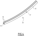
- An alternative holding member 38 in its flexed configuration is shown in figure 4 .
- the holding element 38 When it is in its holding configuration, the holding element 38 bears, on one side, against the locking face 35, and on the other side against the edge 20 of the plate 12, so that it presses the edge 20 of the plate 12 against the pressure face 36. In other words, the edge 20 of the plate 12 is sandwiched between the pressure face 36 and the element holding 38.
- Holder 38 has a release configuration, wherein holder 38 is upright and allows movement of plate 12 within slide slot 32 when plate 12 is inserted into slide slot 32. straightened, we mean that the holding element 38 is substantially rectilinear in the longitudinal direction.
- the edge 20 of the plate 12 is arranged between the holding element 38 and the pressure face 36 and is movable relative to the frame 22.
- the plate 12 is for example movable substantially in translation along the longitudinal axis X-X' by relative to the holding element 38 and relative to the frame 22 allowing rapid dismantling of the plate 12.
- a clearance between the pressure face 36, the holding element 38 and the plate 12 allows for example the displacement of the edge of the plate 12 with respect to the pressure face 36 and the holding element 38.
- the sum of the height of the holding element 38 added to the thickness of the edge 20 of the plate 12 is less than the height h of the slot, to allow free movement of the plate 12 in the slide.
- the holding element 38 is a channel 42. Such holding element 38 is further illustrated holding the electronic component plate 12 from the top of the figure 2 .
- the U-section 42 extends along the longitudinal axis X-X'.
- the U-shaped channel 42 comprises a channel base 44, the channel base 44 corresponding to a section of the channel forming the base of the U of the U-shaped channel 42, as well as legs 46 of channel, extending from the base to form the U-shaped profile.
- the U-shaped profile 42 delimits a profile volume 47 extending between the tabs 46 of the profile.
- the holding element 38 is preferably an extrusion part in a conductive material such as aluminum or copper, or else in a spring steel.
- the holding element 38 of the picture 3 has a more complex shape allowing unidirectional buckling.
- the holding member can be a square tube having top openings.
- the retaining element 38 directly retains a retaining bar 48 of the locking element 23.
- the U-shaped channel forming the holding element 38 When in its holding configuration 44, the U-shaped channel forming the holding element 38 is flexed perpendicular to the channel base 44, in the same direction as the channel legs 46, as illustrated in the figure below. figure 4 .
- the edge 20 of the electronic component plate 12 is clamped between the profile base 44 and the pressure face 36 when the U-shaped profile forming the holding element 38 is in its holding configuration, the tabs 46 of the profile U bearing against the locking face 35.
- the locking element 40 is movable between an unlocking position and a locking position.
- the locking element 40 When it is in its locking position, the locking element 40 maintains the holding element 38 in its holding configuration.
- the locking element 40 is connected to the holding element 38 so that the locking element 40 drives the holding element 38 towards its holding configuration when it passes from its unlocked position to its locked position. and so that the locking element 40 drives the holding element 38 towards its release configuration when it passes from its locking position to its unlocking position.
- the locking element 40 comprises a locking bar 48, a locking member 50 and a clamping member 52.
- the locking element comprises for example at least one spacer 54.
- the locking bar 48 extends substantially parallel to the longitudinal axis X-X'.
- the locking bar 48 extends for example in the profile volume 47.
- the locking bar 48 comprises a first end 56 and a second end 58.
- the first end 56 and the second end 58 of the locking bar 48 are for example threaded.
- the holding element 38 comprises a punching/stamping capable of holding the locking bar 48 of the locking device 23 in the holding element 38 when the latter is manipulated or else in the locking configuration. This prevents the locking bar 48 from moving away from the holding element 38 and the locking bar 48 coming out of the profile volume 47, for example.
- the locking member 50 is disposed at the first end 56 of the locking bar 48.
- the locking member 50 is configured to be stationary relative to the locking bar 48 when a force is applied along the longitudinal axis X-X' on blocking member 50.
- the locking member 50 is for example screwed onto the first end 56 of the locking bar 48.
- the clamping member 52 is disposed at the second end 58 of the locking bar 48.
- the clamping member 52 is longitudinally movable relative to the locking bar 48, to move the locking element 40 between its unlocking positions and locking.
- the position of the locking element 40 is in particular determined by the gap between the clamping member 52 and the locking member 50.
- the unlocking position corresponding to a position of the clamping member 52 relative to the locking member 50 in which the gap between the locking member 50 and the clamping member 52 is greater than said gap, when the locking element 40 is in a locking position.
- the clamping member 52 is for example screwed onto the second end 58 of the locking bar 48.
- the locking element 40 is for example movable between its locking and unlocking positions respectively by screwing, unscrewing, of the locking member. clamp 52 on the locking bar 48.
- the gap between the clamping member 52 and the locking member 50 when the locking element 40 is in its unlocked position is for example greater than the longitudinal length of the U-section 42 when the U-section forming the the holding element 38 is in its release configuration.
- the U-section is then free between the clamping member 52 and the blocking member 50, the U-section 42 being in a straightened position in which it is substantially rectilinear along the longitudinal axis X-X'.
- the gap between the clamping member 52 and the locking member 50 when the locking element 40 is in its locking position is for example less than the longitudinal length of the U-section 42 when the U-section forming the the holding element 38 is in its holding configuration.
- the locking element 48 is in its locking position, the U-section 42 is clamped longitudinally between the clamping member 52 and the locking member 50, the longitudinal clamping of the U-section 42 causing the bending of said section U-shaped perpendicular to the longitudinal axis X-X'.
- the spacer 54 is for example placed between the locking member 50 and the U-section 42. Alternatively, or in addition, the spacer 54 is placed between the clamping member 52 and the U-section 42.
- the spacer 54 is for example configured to allow rotation of the clamping member 52 and/or of the locking member 50 while distributing the longitudinal clamping force exerted by the clamping member 52 and of the locking member 50 at the ends of the U-shaped section 42.
- the spacer 54 is for example smooth and makes it possible, for example, to contain the screwing friction between the clamping member 52 and the U-shaped section 42.
- the heat pipe 28 is arranged on the electronic component plate 12.
- the heat pipe is for example part of the electronic component plate 12.
- the heat pipe 28 electrically connects at least one or the electronic component 16 to the heat conducting section 18.
- the cover 24 is configured to be fixed on the frame 22.
- the cooling device 14 comprises two covers fixed to the frame 22.
- the at least one lid 24 and the frame together define a sealed interior volume 60 when the or each lid 24 is fixed to the frame 22.
- Each lid 24 extends for example opposite an opening of the frame 22 to close the frame. 22 and together define the sealed interior volume 60.
- the at least one heat sink 26 extends outside the interior volume.
- the at least one heat sink 26 is attached to frame 22 and/or cover 24.
- the at least one heat sink 26 is configured to dissipate the heat transmitted by the frame 22 to an exterior of the frame.
- the at least one heat sink 26 is for example a finned heat sink as shown in figure 1 .
- at least one heat sink 26 is a liquid sink (not shown).
- a cooling device 14 as aforesaid is provided, the locking devices disposed in a pair of slide slots 32 being provided with their retaining elements 38 in a releasing configuration and their locking elements 40 in an unlocking position, the or the cover(s) 24 being placed away from the frame 22.
- An electronic component plate 12 is then inserted into each of the slider slots 32 of the pair of slider slots 32.
- the edges 20 of the electronic component plate 12 are slid between the holder 38 and the pressure face 36 into each of the slide slots 32 of the pair of slide slots 32.
- the locking element 40 is then moved from its unlocked position to its locked position to bring the holding element from its release configuration to its holding configuration.
- the holding element 38 in its holding configuration is flexed so as to press the edges 20 of the electronic component plate 12 against the pressure face 36.
- the or each cover 24 is then fixed to the frame 22 so as to define the sealed interior volume 60.
- the assembly/disassembly and the maintenance of the component plate 12 is carried out by access to the covers 24.
- the heat generated by each electronic component 16 is conducted into the plate 12.
- the plate 12 is pressed against the pressure face 36 so that the heat is conducted from the plate 12 to the frame 22.
- the heat is then preferably transmitted by conduction from the frame to at least one heat sink to dissipate the heat outside the frame.
- This embodiment proposes integrating the holding element 38 into the frame 22 to reduce the number of parts and make the device more compact. It also makes it possible to carry out a locking by one or the other of the ends of the holding element 38.
- the holding element 38 comprises a flat bar 62 with a longitudinal axis XX' instead of a U-section 42. Such a holding element 38 is further illustrated now at the level of the electronic component plate 12 of the bottom of the there picture 2
- the locking element 40 comprises at least two fasteners 64 instead of a locking bar 48, a locking member 50 and a clamping member 42.
- Each fastener 64 is configured to be screwed into frame 22 to move locking member 40 between its unlocked and locked positions.
- the flat bar 62 is clamped longitudinally between the two fastening members 64 when the locking element 40 is in its locking position, the longitudinal clamping of the flat bar 62 causing the bending of said flat bar 62.
- the flat bar 62 is a piece made in one piece, for example sheet metal advantageously in a conductive material such as spring steel.
- the flat bar 62 comprises for example a main section and two end sections, the main section being connected at its ends to the two end sections by two folds.
- the main sections extend for example substantially perpendicular to the main section.
- Each end section comprises for example a region for receiving a fastener 64, the flat bar 62 thus being configured to accommodate the fasteners 64.
- the fastener 64 is for example a screw intended to be screwed into the frame 22 and to pass through the flat bar 62.
- the fixing member 64 is configured to bring the two ends of the flat bar 62 together so as to flex the flat bar 62.
- Flat bar 62 is preferably made by simple sheet metal processes such as bending and stamping.
- the flat bar 62 is substantially longer than the depth of the frame 22, in order to move the ends of the flat bar relative to each other and to move the holding element 38 between its holding and release.
Landscapes
- Engineering & Computer Science (AREA)
- Microelectronics & Electronic Packaging (AREA)
- Physics & Mathematics (AREA)
- Thermal Sciences (AREA)
- Aviation & Aerospace Engineering (AREA)
- Cooling Or The Like Of Electrical Apparatus (AREA)
- Encapsulation Of And Coatings For Semiconductor Or Solid State Devices (AREA)
- Cooling Or The Like Of Semiconductors Or Solid State Devices (AREA)
Claims (7)
- Vorrichtung zum Kühlen (14) mindestens einer Platte elektronischer Komponenten (12), umfassend:- ein Gestell (22), umfassend mindestens einen Führungsschlitz (32) zum Aufnehmen eines Rand (20) der Platte (12), wobei der Führungsschlitz (32) durch eine Verriegelungsfläche (35) und eine Druckfläche (36) gegenüber der Verriegelungsfläche (35) begrenzt ist,- eine Verriegelungsvorrichtung (23), die dazu dient, die Platte (12) in dem Gestell (22) in Position zu halten,die Verriegelungsvorrichtung (23) umfassend ein Halteelement (38) zum Aufnehmen in dem Führungsschlitz (32), wobei das Halteelement (38) flexibel ist und vorzugsweise eine allgemein längliche Form aufweist, wobei das Halteelement (38) eine Haltekonfiguration, in der das Halteelement (38) gebogen ist, um den Rand (20) der Platte (12) gegen die Druckfläche (36) zu drücken, wenn der Rand der Platte (12) in dem Führungsschlitz (32) aufgenommen ist, und eine Freigabekonfiguration, in der das Halteelement (38) aufgerichtet ist und eine Bewegung der Platte (12) in dem Führungsschlitz (32) zulässt, aufweist,die Verriegelungsvorrichtung (23) umfassend ein Verriegelungselement (40), das mit dem Halteelement (38) verbunden ist und zwischen einer Entriegelungsposition und einer Verriegelungsposition beweglich ist, sodass das Verriegelungselement (40) das Halteelement (38) in seine Haltekonfiguration treibt, wenn es von seiner Entriegelungsposition in seine Verriegelungsposition bewegt wird, und das Halteelement (38) in seine Freigabekonfiguration treibt, wenn es von seiner Verriegelungsposition in seine Entriegelungsposition bewegt wird, unddadurch gekennzeichnet ist, dass das Halteelement Folgendes umfasst:- ein U-Profil (42) mit einer Längsachse (X-X'), das ein Profilvolumen (47) begrenzt; und wobei das Verriegelungselement (40) Folgendes umfasst:- eine Verriegelungsstange (48), die sich in das Profilvolumen (47) erstreckt,- ein Blockierelement (50), das an einem ersten Ende (56) der Verriegelungsstange (48) angeordnet ist, und- ein Klemmelement (52), das an einem zweiten Ende (58) der Verriegelungsstange (48) angeordnet ist,wobei das Klemmelement (52) in Längsrichtung in Bezug auf die Verriegelungsstange (48) verschiebbar ist, um das Verriegelungselement (40) zwischen seiner Entriegelungsposition und seiner Verriegelungsposition zu bewegen, wobei das U-Profil (42) in Längsrichtung zwischen dem Klemmelement (52) und dem Blockierelement (50) eingeklemmt wird, wenn das Verriegelungselement (40) in seiner Verriegelungsposition ist, wobei das Einklemmen des U-Profils (42) in Längsrichtung die Biegung des U-Profils bewirkt.
- Kühlvorrichtung (14) nach Anspruch 1, wobei das erste (56) und das zweite (58) Ende der Verriegelungsstange (48) mit Gewinde versehen sind, wobei das Blockierelement (50) bzw. das Klemmelement (52) auf das erste (56) bzw. das zweite (58) Ende der Verriegelungsstange (48) aufgeschraubt ist.
- Kühlvorrichtung (14) nach Anspruch 1 oder 2, wobei das Verriegelungselement (40) mindestens einen Abstandhalter (54) umfasst, der zwischen dem Klemmelement (50) und dem U-Profil (42) angeordnet ist, und/oder mindestens einen Abstandhalter (54), der zwischen dem Klemmelement (52) und dem U-Profil (42) angeordnet ist.
- Kühlvorrichtung (14) nach einem der vorherigen Ansprüche, wobei das Gestell (22) eine Vielzahl von Paaren von Führungsschlitzen (32) umfasst, wobei jedes Paar von Führungsschlitzen (32) durch zwei Führungsschlitze (32) gebildet ist, deren Verriegelungsflächen (35) und Druckflächen (36) sich in einer jeweils gleichen Ebene erstrecken, die Kühlvorrichtung (14) umfassend eine Verriegelungsvorrichtung (23), die in jedem Führungsschlitz (32) angeordnet ist, wobei sich eine gleiche Platte elektronischer Komponenten (12) in die Führungsschlitz (32) eines gleichen Paars von Führungsschlitz (32) erstreckt.
- Kühlvorrichtung (14) nach einem der vorherigen Ansprüche, wobei die Kühlvorrichtung (14) mindestens ein Wärmerohr (28) umfasst, wobei die Platte elektronischer Komponenten (12) mindestens eine elektronische Komponente (16) und eine wärmeleitende Platte (18) umfasst, wobei die mindestens eine elektronische Komponente (16) durch mindestens ein Wärmerohr (28) thermisch mit der wärmeleitenden Platte (18) verbunden ist.
- Kühlvorrichtung (14) nach einem der vorherigen Ansprüche, wobei die Kühlvorrichtung (14) mindestens einen Deckel (24) umfasst, der konfiguriert ist, um an dem Gestell (22) befestigt zu werden, wobei der mindestens eine Deckel (24) und das Gestell (22) zusammen ein abgedichtetes Innenvolumen (60) definieren, wenn der oder jeder Deckel (24) an dem Gestell (22) befestigt ist.
- Kühlvorrichtung (14) nach Anspruch 6, wobei die Kühlvorrichtung (14) mindestens einen Kühlkörper (26) umfasst, wobei sich der mindestens eine Kühlkörper (26) aus dem Innenvolumen (60) erstreckt und an dem Gestell (22) und/oder dem Deckel (24) befestigt ist.
Applications Claiming Priority (1)
| Application Number | Priority Date | Filing Date | Title |
|---|---|---|---|
| FR2103080A FR3121317A1 (fr) | 2021-03-26 | 2021-03-26 | Dispositif de refroidissement de composants électroniques |
Publications (2)
| Publication Number | Publication Date |
|---|---|
| EP4064807A1 EP4064807A1 (de) | 2022-09-28 |
| EP4064807B1 true EP4064807B1 (de) | 2023-03-29 |
Family
ID=76034773
Family Applications (1)
| Application Number | Title | Priority Date | Filing Date |
|---|---|---|---|
| EP22164351.3A Active EP4064807B1 (de) | 2021-03-26 | 2022-03-25 | Kühlvorrichtung für elektronische komponenten |
Country Status (3)
| Country | Link |
|---|---|
| EP (1) | EP4064807B1 (de) |
| ES (1) | ES2947211T3 (de) |
| FR (1) | FR3121317A1 (de) |
Family Cites Families (4)
| Publication number | Priority date | Publication date | Assignee | Title |
|---|---|---|---|---|
| FR2886508A1 (fr) * | 2005-05-31 | 2006-12-01 | Sagem | Cale expansible et systeme comprenant un module, un receptacle et une telle cale intercalee entre eux |
| US20070253169A1 (en) * | 2006-05-01 | 2007-11-01 | Honeywell International Inc. | Wedgelock device for increased thermal conductivity of a printed wiring wiring assembly |
| US20140328616A1 (en) * | 2013-05-03 | 2014-11-06 | Utah State University Research Foundation | Spring Lock |
| US10129996B2 (en) | 2016-03-02 | 2018-11-13 | Creare Llc | High-pressure card locks for maximizing heat transfer from electronics cards to card cages |
-
2021
- 2021-03-26 FR FR2103080A patent/FR3121317A1/fr active Pending
-
2022
- 2022-03-25 EP EP22164351.3A patent/EP4064807B1/de active Active
- 2022-03-25 ES ES22164351T patent/ES2947211T3/es active Active
Also Published As
| Publication number | Publication date |
|---|---|
| EP4064807A1 (de) | 2022-09-28 |
| FR3121317A1 (fr) | 2022-09-30 |
| ES2947211T3 (es) | 2023-08-03 |
Similar Documents
| Publication | Publication Date | Title |
|---|---|---|
| FR2942935A1 (fr) | Dispositif de retenue de carte de circuit imprime | |
| EP1357650B1 (de) | Verbindungsvorrichtung für elektronisches Gehäuse | |
| EP2612489B1 (de) | Stütze für ein mobiles endgerät für die aufnahme von mobilen endgeräten unterschiedlicher grössen | |
| EP2355643A1 (de) | Hilfsvorrichtung zur Ableitung durch Wärmeleitung, die über eine elektronische Karte gesteuert wird | |
| FR2966318A1 (fr) | Dissipateur thermique pour module d'extension interchangeable pouvant etre connecte a une carte informatique | |
| EP4064807B1 (de) | Kühlvorrichtung für elektronische komponenten | |
| EP3827207B1 (de) | Vorrichtung zur befestigung von paneelen, insbesondere von solarpaneelen | |
| WO2016128396A1 (fr) | Boîtier d'un dispositif de chauffage electrique | |
| FR2665591A1 (fr) | Ensemble de montage pour emetteur-recepteur. | |
| EP3206469B1 (de) | Halterungsvorrichtung für mindestens zwei leiterplatten, entsprechendes elektronisches modul und entsprechendes elektronisches system | |
| EP2320531A1 (de) | Schienenauflagerung zur Montage von modularen elektrischen Geräten und Fahrgestell für elektrischen Verteiler- oder Schaltkasten, der eine solche Schienenauflagerung umfasst | |
| EP2362720A1 (de) | Elektronisches module und elektronische Anordnung umfassend dieses Modul | |
| EP3782867B1 (de) | Elektrische anschlussvorrichtung für ein fahrzeug, entsprechendes fahrzeug und installationsverfahren | |
| EP1801331B1 (de) | Griffstütze | |
| WO1991000391A1 (fr) | Dispositif de fixation elastique d'un rail de chemin de fer sur son support | |
| FR3128754A1 (fr) | Mécanisme de blocage | |
| FR2669971A1 (fr) | Dispositif pour relier plusieurs pieces ou parties les unes aux autres. | |
| FR3064400A1 (fr) | Dispositif de refroidissement pour batterie de vehicule automobile | |
| EP3222488B1 (de) | Halterung zur befestigung einer eurobalise, und befestigungssystem, das mindestens eine solche halterung umfasst | |
| FR2932927A1 (fr) | Unite d'entrainement de fixation et de retrait d'objets, et unite de type connecteur | |
| EP3513386B1 (de) | Elektronisches zahlungsendgerät mit einteiligem magnetkartenleseelement mit einem metallschieber, zugehöriges montageverfahren | |
| FR3051310A3 (fr) | Kit de fixation d'un chassis d'amplificateur ou de haut-parleur | |
| EP2658057B1 (de) | Befestigungsvorrichtung zur Montage eines Elektrogeräteelements im Innern einer Öffnung in einer Einbauwand und Gesamtheit dieser Befestigungsvorrichtungen | |
| FR2979793A1 (fr) | Dispositif pour l'ablocage d'une carte electronique dans une glissiere | |
| FR3095580A1 (fr) | Systeme d'attache clipsable et mobilier le comprenant |
Legal Events
| Date | Code | Title | Description |
|---|---|---|---|
| PUAI | Public reference made under article 153(3) epc to a published international application that has entered the european phase |
Free format text: ORIGINAL CODE: 0009012 |
|
| STAA | Information on the status of an ep patent application or granted ep patent |
Free format text: STATUS: THE APPLICATION HAS BEEN PUBLISHED |
|
| STAA | Information on the status of an ep patent application or granted ep patent |
Free format text: STATUS: REQUEST FOR EXAMINATION WAS MADE |
|
| AK | Designated contracting states |
Kind code of ref document: A1 Designated state(s): AL AT BE BG CH CY CZ DE DK EE ES FI FR GB GR HR HU IE IS IT LI LT LU LV MC MK MT NL NO PL PT RO RS SE SI SK SM TR |
|
| 17P | Request for examination filed |
Effective date: 20220906 |
|
| RBV | Designated contracting states (corrected) |
Designated state(s): AL AT BE BG CH CY CZ DE DK EE ES FI FR GB GR HR HU IE IS IT LI LT LU LV MC MK MT NL NO PL PT RO RS SE SI SK SM TR |
|
| GRAP | Despatch of communication of intention to grant a patent |
Free format text: ORIGINAL CODE: EPIDOSNIGR1 |
|
| STAA | Information on the status of an ep patent application or granted ep patent |
Free format text: STATUS: GRANT OF PATENT IS INTENDED |
|
| RIC1 | Information provided on ipc code assigned before grant |
Ipc: F16B 2/06 20060101ALI20221028BHEP Ipc: H05K 7/20 20060101ALI20221028BHEP Ipc: H05K 7/14 20060101AFI20221028BHEP |
|
| INTG | Intention to grant announced |
Effective date: 20221115 |
|
| GRAS | Grant fee paid |
Free format text: ORIGINAL CODE: EPIDOSNIGR3 |
|
| GRAA | (expected) grant |
Free format text: ORIGINAL CODE: 0009210 |
|
| STAA | Information on the status of an ep patent application or granted ep patent |
Free format text: STATUS: THE PATENT HAS BEEN GRANTED |
|
| AK | Designated contracting states |
Kind code of ref document: B1 Designated state(s): AL AT BE BG CH CY CZ DE DK EE ES FI FR GB GR HR HU IE IS IT LI LT LU LV MC MK MT NL NO PL PT RO RS SE SI SK SM TR |
|
| REG | Reference to a national code |
Ref country code: CH Ref legal event code: EP |
|
| REG | Reference to a national code |
Ref country code: DE Ref legal event code: R096 Ref document number: 602022000023 Country of ref document: DE |
|
| REG | Reference to a national code |
Ref country code: AT Ref legal event code: REF Ref document number: 1557564 Country of ref document: AT Kind code of ref document: T Effective date: 20230415 |
|
| REG | Reference to a national code |
Ref country code: IE Ref legal event code: FG4D Free format text: LANGUAGE OF EP DOCUMENT: FRENCH |
|
| REG | Reference to a national code |
Ref country code: LT Ref legal event code: MG9D |
|
| PG25 | Lapsed in a contracting state [announced via postgrant information from national office to epo] |
Ref country code: RS Free format text: LAPSE BECAUSE OF FAILURE TO SUBMIT A TRANSLATION OF THE DESCRIPTION OR TO PAY THE FEE WITHIN THE PRESCRIBED TIME-LIMIT Effective date: 20230329 Ref country code: NO Free format text: LAPSE BECAUSE OF FAILURE TO SUBMIT A TRANSLATION OF THE DESCRIPTION OR TO PAY THE FEE WITHIN THE PRESCRIBED TIME-LIMIT Effective date: 20230629 Ref country code: LV Free format text: LAPSE BECAUSE OF FAILURE TO SUBMIT A TRANSLATION OF THE DESCRIPTION OR TO PAY THE FEE WITHIN THE PRESCRIBED TIME-LIMIT Effective date: 20230329 Ref country code: LT Free format text: LAPSE BECAUSE OF FAILURE TO SUBMIT A TRANSLATION OF THE DESCRIPTION OR TO PAY THE FEE WITHIN THE PRESCRIBED TIME-LIMIT Effective date: 20230329 Ref country code: HR Free format text: LAPSE BECAUSE OF FAILURE TO SUBMIT A TRANSLATION OF THE DESCRIPTION OR TO PAY THE FEE WITHIN THE PRESCRIBED TIME-LIMIT Effective date: 20230329 |
|
| REG | Reference to a national code |
Ref country code: NL Ref legal event code: MP Effective date: 20230329 |
|
| REG | Reference to a national code |
Ref country code: ES Ref legal event code: FG2A Ref document number: 2947211 Country of ref document: ES Kind code of ref document: T3 Effective date: 20230803 |
|
| REG | Reference to a national code |
Ref country code: AT Ref legal event code: MK05 Ref document number: 1557564 Country of ref document: AT Kind code of ref document: T Effective date: 20230329 |
|
| PG25 | Lapsed in a contracting state [announced via postgrant information from national office to epo] |
Ref country code: SE Free format text: LAPSE BECAUSE OF FAILURE TO SUBMIT A TRANSLATION OF THE DESCRIPTION OR TO PAY THE FEE WITHIN THE PRESCRIBED TIME-LIMIT Effective date: 20230329 Ref country code: NL Free format text: LAPSE BECAUSE OF FAILURE TO SUBMIT A TRANSLATION OF THE DESCRIPTION OR TO PAY THE FEE WITHIN THE PRESCRIBED TIME-LIMIT Effective date: 20230329 Ref country code: GR Free format text: LAPSE BECAUSE OF FAILURE TO SUBMIT A TRANSLATION OF THE DESCRIPTION OR TO PAY THE FEE WITHIN THE PRESCRIBED TIME-LIMIT Effective date: 20230630 Ref country code: FI Free format text: LAPSE BECAUSE OF FAILURE TO SUBMIT A TRANSLATION OF THE DESCRIPTION OR TO PAY THE FEE WITHIN THE PRESCRIBED TIME-LIMIT Effective date: 20230329 |
|
| P01 | Opt-out of the competence of the unified patent court (upc) registered |
Effective date: 20230823 |
|
| PG25 | Lapsed in a contracting state [announced via postgrant information from national office to epo] |
Ref country code: SM Free format text: LAPSE BECAUSE OF FAILURE TO SUBMIT A TRANSLATION OF THE DESCRIPTION OR TO PAY THE FEE WITHIN THE PRESCRIBED TIME-LIMIT Effective date: 20230329 Ref country code: RO Free format text: LAPSE BECAUSE OF FAILURE TO SUBMIT A TRANSLATION OF THE DESCRIPTION OR TO PAY THE FEE WITHIN THE PRESCRIBED TIME-LIMIT Effective date: 20230329 Ref country code: PT Free format text: LAPSE BECAUSE OF FAILURE TO SUBMIT A TRANSLATION OF THE DESCRIPTION OR TO PAY THE FEE WITHIN THE PRESCRIBED TIME-LIMIT Effective date: 20230731 Ref country code: EE Free format text: LAPSE BECAUSE OF FAILURE TO SUBMIT A TRANSLATION OF THE DESCRIPTION OR TO PAY THE FEE WITHIN THE PRESCRIBED TIME-LIMIT Effective date: 20230329 Ref country code: AT Free format text: LAPSE BECAUSE OF FAILURE TO SUBMIT A TRANSLATION OF THE DESCRIPTION OR TO PAY THE FEE WITHIN THE PRESCRIBED TIME-LIMIT Effective date: 20230329 |
|
| PG25 | Lapsed in a contracting state [announced via postgrant information from national office to epo] |
Ref country code: SK Free format text: LAPSE BECAUSE OF FAILURE TO SUBMIT A TRANSLATION OF THE DESCRIPTION OR TO PAY THE FEE WITHIN THE PRESCRIBED TIME-LIMIT Effective date: 20230329 Ref country code: PL Free format text: LAPSE BECAUSE OF FAILURE TO SUBMIT A TRANSLATION OF THE DESCRIPTION OR TO PAY THE FEE WITHIN THE PRESCRIBED TIME-LIMIT Effective date: 20230329 Ref country code: IS Free format text: LAPSE BECAUSE OF FAILURE TO SUBMIT A TRANSLATION OF THE DESCRIPTION OR TO PAY THE FEE WITHIN THE PRESCRIBED TIME-LIMIT Effective date: 20230729 |
|
| REG | Reference to a national code |
Ref country code: DE Ref legal event code: R097 Ref document number: 602022000023 Country of ref document: DE |
|
| PG25 | Lapsed in a contracting state [announced via postgrant information from national office to epo] |
Ref country code: DK Free format text: LAPSE BECAUSE OF FAILURE TO SUBMIT A TRANSLATION OF THE DESCRIPTION OR TO PAY THE FEE WITHIN THE PRESCRIBED TIME-LIMIT Effective date: 20230329 Ref country code: CZ Free format text: LAPSE BECAUSE OF FAILURE TO SUBMIT A TRANSLATION OF THE DESCRIPTION OR TO PAY THE FEE WITHIN THE PRESCRIBED TIME-LIMIT Effective date: 20230329 |
|
| PLBE | No opposition filed within time limit |
Free format text: ORIGINAL CODE: 0009261 |
|
| STAA | Information on the status of an ep patent application or granted ep patent |
Free format text: STATUS: NO OPPOSITION FILED WITHIN TIME LIMIT |
|
| 26N | No opposition filed |
Effective date: 20240103 |
|
| PG25 | Lapsed in a contracting state [announced via postgrant information from national office to epo] |
Ref country code: SI Free format text: LAPSE BECAUSE OF FAILURE TO SUBMIT A TRANSLATION OF THE DESCRIPTION OR TO PAY THE FEE WITHIN THE PRESCRIBED TIME-LIMIT Effective date: 20230329 |
|
| PG25 | Lapsed in a contracting state [announced via postgrant information from national office to epo] |
Ref country code: SI Free format text: LAPSE BECAUSE OF FAILURE TO SUBMIT A TRANSLATION OF THE DESCRIPTION OR TO PAY THE FEE WITHIN THE PRESCRIBED TIME-LIMIT Effective date: 20230329 |
|
| PG25 | Lapsed in a contracting state [announced via postgrant information from national office to epo] |
Ref country code: BG Free format text: LAPSE BECAUSE OF FAILURE TO SUBMIT A TRANSLATION OF THE DESCRIPTION OR TO PAY THE FEE WITHIN THE PRESCRIBED TIME-LIMIT Effective date: 20230329 |
|
| PG25 | Lapsed in a contracting state [announced via postgrant information from national office to epo] |
Ref country code: LU Free format text: LAPSE BECAUSE OF NON-PAYMENT OF DUE FEES Effective date: 20240325 |
|
| PG25 | Lapsed in a contracting state [announced via postgrant information from national office to epo] |
Ref country code: MC Free format text: LAPSE BECAUSE OF FAILURE TO SUBMIT A TRANSLATION OF THE DESCRIPTION OR TO PAY THE FEE WITHIN THE PRESCRIBED TIME-LIMIT Effective date: 20230329 |
|
| PG25 | Lapsed in a contracting state [announced via postgrant information from national office to epo] |
Ref country code: MC Free format text: LAPSE BECAUSE OF FAILURE TO SUBMIT A TRANSLATION OF THE DESCRIPTION OR TO PAY THE FEE WITHIN THE PRESCRIBED TIME-LIMIT Effective date: 20230329 Ref country code: LU Free format text: LAPSE BECAUSE OF NON-PAYMENT OF DUE FEES Effective date: 20240325 Ref country code: BG Free format text: LAPSE BECAUSE OF FAILURE TO SUBMIT A TRANSLATION OF THE DESCRIPTION OR TO PAY THE FEE WITHIN THE PRESCRIBED TIME-LIMIT Effective date: 20230329 |
|
| REG | Reference to a national code |
Ref country code: BE Ref legal event code: MM Effective date: 20240331 |
|
| PG25 | Lapsed in a contracting state [announced via postgrant information from national office to epo] |
Ref country code: BE Free format text: LAPSE BECAUSE OF NON-PAYMENT OF DUE FEES Effective date: 20240331 |
|
| PG25 | Lapsed in a contracting state [announced via postgrant information from national office to epo] |
Ref country code: IE Free format text: LAPSE BECAUSE OF NON-PAYMENT OF DUE FEES Effective date: 20240325 |
|
| PG25 | Lapsed in a contracting state [announced via postgrant information from national office to epo] |
Ref country code: IE Free format text: LAPSE BECAUSE OF NON-PAYMENT OF DUE FEES Effective date: 20240325 Ref country code: BE Free format text: LAPSE BECAUSE OF NON-PAYMENT OF DUE FEES Effective date: 20240331 |
|
| PGFP | Annual fee paid to national office [announced via postgrant information from national office to epo] |
Ref country code: ES Payment date: 20250429 Year of fee payment: 4 |
|
| PG25 | Lapsed in a contracting state [announced via postgrant information from national office to epo] |
Ref country code: CY Free format text: LAPSE BECAUSE OF FAILURE TO SUBMIT A TRANSLATION OF THE DESCRIPTION OR TO PAY THE FEE WITHIN THE PRESCRIBED TIME-LIMIT; INVALID AB INITIO Effective date: 20220325 |
|
| REG | Reference to a national code |
Ref country code: CH Ref legal event code: H13 Free format text: ST27 STATUS EVENT CODE: U-0-0-H10-H13 (AS PROVIDED BY THE NATIONAL OFFICE) Effective date: 20251023 |
|
| PG25 | Lapsed in a contracting state [announced via postgrant information from national office to epo] |
Ref country code: TR Free format text: LAPSE BECAUSE OF FAILURE TO SUBMIT A TRANSLATION OF THE DESCRIPTION OR TO PAY THE FEE WITHIN THE PRESCRIBED TIME-LIMIT Effective date: 20230329 |
|
| PG25 | Lapsed in a contracting state [announced via postgrant information from national office to epo] |
Ref country code: CH Free format text: LAPSE BECAUSE OF NON-PAYMENT OF DUE FEES Effective date: 20250331 |
|
| PGFP | Annual fee paid to national office [announced via postgrant information from national office to epo] |
Ref country code: DE Payment date: 20260319 Year of fee payment: 5 |
|
| PGFP | Annual fee paid to national office [announced via postgrant information from national office to epo] |
Ref country code: IT Payment date: 20260324 Year of fee payment: 5 |
|
| PGFP | Annual fee paid to national office [announced via postgrant information from national office to epo] |
Ref country code: FR Payment date: 20260323 Year of fee payment: 5 |