EP2355921B1 - Verfahren und vorrichtung zur behandlung mindestens einer in einer flüssigkeit transportierten verbindung - Google Patents
Verfahren und vorrichtung zur behandlung mindestens einer in einer flüssigkeit transportierten verbindung Download PDFInfo
- Publication number
- EP2355921B1 EP2355921B1 EP09803818.5A EP09803818A EP2355921B1 EP 2355921 B1 EP2355921 B1 EP 2355921B1 EP 09803818 A EP09803818 A EP 09803818A EP 2355921 B1 EP2355921 B1 EP 2355921B1
- Authority
- EP
- European Patent Office
- Prior art keywords
- radial
- cavitation
- chamber
- inlet orifice
- liquid
- Prior art date
- Legal status (The legal status is an assumption and is not a legal conclusion. Google has not performed a legal analysis and makes no representation as to the accuracy of the status listed.)
- Active
Links
Images




Classifications
-
- C—CHEMISTRY; METALLURGY
- C02—TREATMENT OF WATER, WASTE WATER, SEWAGE, OR SLUDGE
- C02F—TREATMENT OF WATER, WASTE WATER, SEWAGE, OR SLUDGE
- C02F1/00—Treatment of water, waste water, or sewage
- C02F1/34—Treatment of water, waste water, or sewage with mechanical oscillations
-
- B—PERFORMING OPERATIONS; TRANSPORTING
- B01—PHYSICAL OR CHEMICAL PROCESSES OR APPARATUS IN GENERAL
- B01F—MIXING, e.g. DISSOLVING, EMULSIFYING OR DISPERSING
- B01F25/00—Flow mixers; Mixers for falling materials, e.g. solid particles
- B01F25/40—Static mixers
- B01F25/44—Mixers in which the components are pressed through slits
- B01F25/441—Mixers in which the components are pressed through slits characterised by the configuration of the surfaces forming the slits
- B01F25/4412—Mixers in which the components are pressed through slits characterised by the configuration of the surfaces forming the slits the slits being formed between opposed planar surfaces, e.g. pushed again each other by springs
- B01F25/44121—Mixers in which the components are pressed through slits characterised by the configuration of the surfaces forming the slits the slits being formed between opposed planar surfaces, e.g. pushed again each other by springs with a plurality of parallel slits, e.g. formed between stacked plates
-
- B—PERFORMING OPERATIONS; TRANSPORTING
- B01—PHYSICAL OR CHEMICAL PROCESSES OR APPARATUS IN GENERAL
- B01F—MIXING, e.g. DISSOLVING, EMULSIFYING OR DISPERSING
- B01F25/00—Flow mixers; Mixers for falling materials, e.g. solid particles
- B01F25/40—Static mixers
-
- B—PERFORMING OPERATIONS; TRANSPORTING
- B01—PHYSICAL OR CHEMICAL PROCESSES OR APPARATUS IN GENERAL
- B01F—MIXING, e.g. DISSOLVING, EMULSIFYING OR DISPERSING
- B01F25/00—Flow mixers; Mixers for falling materials, e.g. solid particles
- B01F25/40—Static mixers
- B01F25/44—Mixers in which the components are pressed through slits
- B01F25/441—Mixers in which the components are pressed through slits characterised by the configuration of the surfaces forming the slits
- B01F25/4412—Mixers in which the components are pressed through slits characterised by the configuration of the surfaces forming the slits the slits being formed between opposed planar surfaces, e.g. pushed again each other by springs
-
- C—CHEMISTRY; METALLURGY
- C02—TREATMENT OF WATER, WASTE WATER, SEWAGE, OR SLUDGE
- C02F—TREATMENT OF WATER, WASTE WATER, SEWAGE, OR SLUDGE
- C02F1/00—Treatment of water, waste water, or sewage
- C02F1/30—Treatment of water, waste water, or sewage by irradiation
- C02F1/32—Treatment of water, waste water, or sewage by irradiation with ultraviolet light
-
- C—CHEMISTRY; METALLURGY
- C02—TREATMENT OF WATER, WASTE WATER, SEWAGE, OR SLUDGE
- C02F—TREATMENT OF WATER, WASTE WATER, SEWAGE, OR SLUDGE
- C02F1/00—Treatment of water, waste water, or sewage
- C02F1/72—Treatment of water, waste water, or sewage by oxidation
-
- C—CHEMISTRY; METALLURGY
- C02—TREATMENT OF WATER, WASTE WATER, SEWAGE, OR SLUDGE
- C02F—TREATMENT OF WATER, WASTE WATER, SEWAGE, OR SLUDGE
- C02F2101/00—Nature of the contaminant
- C02F2101/30—Organic compounds
- C02F2101/306—Pesticides
-
- C—CHEMISTRY; METALLURGY
- C02—TREATMENT OF WATER, WASTE WATER, SEWAGE, OR SLUDGE
- C02F—TREATMENT OF WATER, WASTE WATER, SEWAGE, OR SLUDGE
- C02F2101/00—Nature of the contaminant
- C02F2101/30—Organic compounds
- C02F2101/32—Hydrocarbons, e.g. oil
- C02F2101/322—Volatile compounds, e.g. benzene
-
- C—CHEMISTRY; METALLURGY
- C02—TREATMENT OF WATER, WASTE WATER, SEWAGE, OR SLUDGE
- C02F—TREATMENT OF WATER, WASTE WATER, SEWAGE, OR SLUDGE
- C02F2101/00—Nature of the contaminant
- C02F2101/30—Organic compounds
- C02F2101/36—Organic compounds containing halogen
-
- C—CHEMISTRY; METALLURGY
- C02—TREATMENT OF WATER, WASTE WATER, SEWAGE, OR SLUDGE
- C02F—TREATMENT OF WATER, WASTE WATER, SEWAGE, OR SLUDGE
- C02F2101/00—Nature of the contaminant
- C02F2101/30—Organic compounds
- C02F2101/36—Organic compounds containing halogen
- C02F2101/363—PCB's; PCP's
-
- C—CHEMISTRY; METALLURGY
- C02—TREATMENT OF WATER, WASTE WATER, SEWAGE, OR SLUDGE
- C02F—TREATMENT OF WATER, WASTE WATER, SEWAGE, OR SLUDGE
- C02F2201/00—Apparatus for treatment of water, waste water or sewage
- C02F2201/32—Details relating to UV-irradiation devices
- C02F2201/322—Lamp arrangement
- C02F2201/3223—Single elongated lamp located on the central axis of a turbular reactor
Definitions
- the present invention relates to the field of the treatment of compounds, such as compounds or chemical or organic species or microorganisms.
- Undesirable chemical compounds are often found in polluted water, for example by volatile compounds such as hydrocarbons or chlorinated compounds (trichlorethylene for example) or by low volatility compounds such as PCBs (Polychlorobiphenyl) PCP (Pentachlorophenol) used as fungicides or certain molecules considered as endocrine disruptors. These bodies are most often carcinogenic and cause disorders in animals and men.
- Water may also contain living microorganisms such as bacteria or microscopic algae. It is often desirable to destroy them to avoid pathological effects. This destruction is done with techniques equivalent to those used for chemical compounds, for example by sterilization by chlorine or peroxide, or by ultraviolet radiation irradiation.
- the document JP 11 42432 describes a device in which two opposite flows collide. The resulting flow flows radially and is discharged into a peripheral evacuation chamber, again in the form of dispersion jets.
- the document DE 3728946 discloses a device in which an axial flow is deflected to a radial chamber which has a peripheral opening. This chamber is frustoconical and formed so that its thickness is reduced in going outward. Turbulence effects occur only beyond the peripheral opening of the radial chamber in the large exhaust chamber.
- the document JP 2008/207099 describes a device in which the liquid is introduced axially into a blind hole and is evacuated by divergent frustoconical radial channels arranged in the wall of the blind hole, away from the bottom. It is in fact, in each diverging frustoconical radial channel of a Venturi type operation, axially to this channel.
- the object of the present invention is to produce a particular cavitation capable of improving the mechanical and / or chemical and / or bacteriological effects and / or the micro-organisms on the compound (s) transported in a liquid to be treated.
- the present invention is based on cavitation which causes the formation of bubbles or pockets of vapor in a liquid under the effect of depressions and in which the bubbles or pockets of vapor produced during this depression then condense abruptly when the pressure is rising.
- this rapid condensation also called collapse, takes place in times of for example between one tenth of a second and one microsecond depending on the initial size of the bubble or pocket, this reaction being able to be fast enough for the gases compress and heat up to higher temperatures, for example at 2000 ° C, thereby producing a plasma.
- the present invention seeks in particular to increase the combined effects of the intense turbulence prevailing in the collapse zone of bubbles or cavitation pockets and very high speeds of the wall of the latter; and / or to increase the effects resulting from the plasma produced in the bubbles or cavitation pockets and capable in particular of producing radiation in the liquid; and / or destroying compounds present in bubbles or cavitation pockets; and / or to generate the production of molecules, ions or species or chemical radicals capable of migrating into the liquid and to act on the compounds that the liquid carries; and / or to produce intense sound waves in the liquid.
- the present invention firstly relates to a process for treating a compound, such as a chemical compound and / or organic and / or a microorganism, carried by a liquid.
- This method is such that two substantially radial faces disposed opposite one another delimit between them a radial cavitation chamber, one of said faces having an axial inlet orifice arranged axially in its central part and said faces forming a peripheral opening.
- the liquid, fed axially through the axial inlet orifice is deflected and flows into said radial cavitation chamber in various radial directions towards the peripheral exit opening; and that the thickness of said cavitation chamber (18) between said radial faces is chosen to be between 0.1 and 0.25 times the diameter of said axial inlet orifice, preferably 0.14.
- the liquid flow conditions generate bubbles or pockets of cavitation in the first portion of the radial flow around the central inlet port. Also, bubbles or cavitation pockets implode before reaching the peripheral exit opening, in order to at least partially treat said compound in said cavitation chamber.
- the distance between the axis of said inlet central orifice and said peripheral opening of said cavitation chamber may be chosen to be greater than twice the diameter of said inlet central orifice.
- the ratio between the absolute pressure upstream of said cavitation chamber and the pressure downstream of this chamber may be between 1.5 and 6.
- the present invention also relates to a device for treating at least one compound, such as a chemical compound and / or organic and / or a micro-organic, transported by a liquid.
- a device for treating at least one compound such as a chemical compound and / or organic and / or a micro-organic, transported by a liquid.
- This device comprises a first element having a substantially radial face and a substantially axial inlet of the liquid inlet and a second element having a substantially radial face.
- Said radial faces are arranged vis-à-vis so as to form therebetween a space forming a radial cavitation chamber having a peripheral exit opening, said axial orifice input of the first element opening into a central portion of the cavitation chamber in front of said radial face of the second element.
- the thickness of said cavitation chamber, between said radial faces, is between 0.1 and 0.25 times the diameter of said axial inlet orifice, preferably 0.14.
- the liquid brought axially by the axial inlet orifice, is deflected in the central inlet portion and flows into said radial cavitation chamber in various radial directions towards the peripheral exit opening and the conditions of the the liquid flow generates bubbles or cavitation pockets in the first part of this flow, around the central inlet orifice, and that the bubbles or cavitation pockets implode before reaching the peripheral exit opening, to at least partially treat said compound.
- Said radial faces delimiting said radial cavitation chamber may be parallel.
- the distance between the axis of the central inlet orifice and said peripheral opening of said cavitation chamber may be greater than twice the diameter of said central inlet orifice.
- Said peripheral outlet opening of said radial cavitation chamber may communicate with a secondary chamber connected to at least one outlet passage.
- Another processing means may be associated with said secondary chamber, in particular a transmission means generating ultraviolet radiation in said secondary chamber.
- the first element and the second element may comprise two walls forming between them a space, one of the walls having a plurality of liquid inlet ports and the other wall having a plurality of outlet orifices, so as to forming in said space and between said inlet ports and said outlet ports a plurality of cavitation chambers.
- Said inlet ports may open into an inlet collecting chamber and the outlet openings may open into an outlet collecting chamber, said walls being annular and concentric, preferably cylindrical or concentric, or flat.
- Said first element may have a chamfer on the edge of said axial input orifice, this chamfer being able to be rounded and have a radius of between 0.1 and 0.5 times the distance between said radial faces in the central part of the chamber.
- cavitation or be frustoconical being disposed at an angle of between 30 ° and 60 °, preferably at 45 °, and a height, along the axis of said axial inlet port, between 0.1 and 0.5 times the distance between said radial faces in the central portion of the cavitation chamber.
- a treatment device 1 represented on the Figures 1 to 3 comprises a casing 2 which comprises two opposite shells 3 and 4 having a vertical axis 5 and delimiting between them a radial cavity 6 which is formed between an annular radial face 7 of the shell 3 and an annular radial face 8 of the shell 4.
- shells 3 and 4 may be identical and placed opposite each other.
- a spacer 9 which comprises a disk 10 which has a radial face 11 bearing on the annular radial face 7 of the shell 3 and which comprises a cylindrical peripheral portion 12 projecting from the disk 10 and support on the annular radial face 8 of the shell 4.
- the shells 3 and 4 have adjacent peripheral portions 13 and 14 connected by bolts 15 to fix them and maintain the supports above.
- An annular seal 16 is installed between the periphery of the cylindrical peripheral portion 12 of the spacer 9 and the periphery of the cavity 6, in the annular zone of the radial faces facing adjacent peripheral portions 13 and 14 hulls 3 and 4.
- the shell 3 Inside its annular radial face 7, the shell 3 (first element) has a recess 17 which delimits, with the radial face 11 of the disk 10 (second element), a cavitation chamber 18, the bottom 19 of the recess 17 extending radially, parallel to the radial face 11 of the disc 10.
- the shell 3 has an axial passage 20 which has a central terminal orifice 21, for example cylindrical, which opens axially in the central part of the cavitation chamber 18, through the radial face formed by the bottom 19 of the recess 17 In the passage 20 is engaged and sealingly attached the end of the conduit 22 for feeding a liquid 23, for example by an annular gland system 24.
- the shell 4 has an axial passage 25 which opens axially, for example through a central terminal orifice 26, in the central part of the secondary chamber 27 formed in the spacer 9, opposite the radial cavitation chamber 18.
- the passage 25 is engaged and sealingly attached to the end of the liquid discharge conduit 28, for example by an annular gland system 29.
- the disc 10 of the spacer 9 has a plurality of through passages 30 which open on the one hand in the periphery of the radial cavitation chamber 18 and on the other hand in the secondary chamber 27.
- the through passages 30 are regularly distributed over a circumference so as to constitute a peripheral outlet opening of the radial cavitation chamber 18.
- These through passages 30 may be formed by cylindrical holes or circumferential slots.
- the liquid 23, brought by the supply duct 22, is introduced into the central part of the radial cavitation chamber 18 through the central orifice 21, then is deflected radially in this central part, then flows into the radial cavitation chamber 18 in various radial directions to the peripheral outlet opening formed by the through passages 30. Then, the liquid from the through passages 30 is collected in the secondary chamber 27, then discharged through the exhaust duct 28.
- the conditions of the radial flow of the liquid 23 in the radial cavitation chamber 18, from the central inlet orifice 21 to the peripheral through passages 30, are such that this flow is hydrodynamic, that bubbles or cavitation pockets 31 appear in the first part of this flow, around the central inlet orifice 21, then collapse or implode immediately, before, preferably well before, that these bubbles or cavitation pockets 31 reach the peripheral through passages output 30.
- the cavitation produced is a hydrodynamic cavitation which results from the acceleration of the flow due to a decrease in its passage section followed by a gradual increase in said passage section in an almost radial direction.
- This cavitation makes it possible to create a very sudden rise in pressure in the zone of condensation or collapse, which has the effect of increasing the intensity of the effects described above for a given flow rate.
- the particular form of this device is that the phenomenon is produced with a loss of pressure and therefore a minimum energy expenditure.
- the cavitation pockets or cavities 31 may comprise a pocket or main annular bubble very close to the inlet orifice 21 and bonded to or located against the radial face 19 of the shell 3, supplied with gas dissolved by the liquid which flows.
- This annular main pocket or bubble is divided into smaller sized pockets or bubbles that move away from the center of the chamber and condense, collapse, or implode.
- the cavitation bubbles or cavities 31 produced are able to at least partially treat the compound or compounds transported by the liquid.
- This treatment can be of a chemical, thermal, chemical and thermal order and / or possibly sonic order because the cavitation phenomenon can possibly produce sonic waves radiating in the liquid.
- the formation against the wall 19 and the collapse of the bubbles or vapor pockets 31 can be located in a virtually predetermined manner and / or can be controlled. Because of the adapted thickness of the radial cavitation chamber 18 with respect to the cavitation bubbles or cavities 31 produced, the cavitation concerns all the liquid to be treated flowing in this chamber 18.
- the liquid such as water carries a chemical compound or compounds
- these specific chemical radicals or species being able to react with these chemical compounds and produce other compounds.
- the chemical effects can produce the destruction of compounds present in the bubbles, generally volatile compounds initially dissolved in the liquid by production of molecules, ions or radicals able to migrate in the liquid and to have an action on the compounds that it transported.
- the oxidation by OH ° radicals makes it possible to destroy dissolved molecules that are difficult to eliminate.
- the cavitation bubbles 31 produced can make it possible to attack these micro-organisms and / or films or clusters thereof, to destroy them, to disperse or dislocate them by chemical, mechanical or intense pressure waves.
- the flow conditions of the liquid in the cavitation chamber 18 of the treatment device 1 may result from a subsequent dimensioning.
- the thickness of the cavitation chamber 18 between the opposite radial faces 7 and 19 may be between 0.1 and 0.25 times the diameter of the central supply orifice 21.
- the thickness of the cavitation chamber 18 may in particular be equal to 0.14 times the diameter of the central supply orifice 21.
- the distance between the axis 5 of the central supply orifice 21 and the circumference on which is formed the peripheral opening of the cavitation chamber 18 determined by the through passages 30 may be greater than 2.5 times the diameter of the central supply port 21
- the ratio between the inlet pressure and the outlet pressure may be between 1.5 and 6.
- the diameter of the supply orifice 21 may be equal to 8 mm
- the thickness of the chamber of cavitation 18 may be equal to 1.12 mm
- the distance between the axis 5 of the central supply orifice 21 and the circumference on which is formed the peripheral opening of the cavitation chamber 18 determined by the through passages 30 may be equal to 30 mm.
- said first element 3 may have a rounded bevel 21a formed on the edge of the axial inlet orifice 21 and joining the face 17.
- This rounded bevel 21a may have a radius r between 0.1 and 0.5 times the distance between the radial faces 11 and 19 in the central part of the cavitation chamber 18.
- said first element 3 may have a frustoconical bevel 21b arranged on the edge of the axial inlet orifice 21.
- This frustoconical bevel 21b may be disposed at an angle of between 30 ° and 60 °, preferably at 45 °.
- Its height h , along the axis of the axial inlet orifice 21, can be between 0.1 and 0.5 times the distance between the radial faces 11 and 19 in the central part of the cavitation chamber 18.
- the chamfers 21a or 21b may facilitate the formation of the cavitation pocket 31 at their periphery.
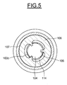
- FIG. 1 it can be seen that another processing device 100 has been shown which comprises a cylinder 101 (first element) which has a radial end face 102 in which a cylindrical recess 103 is formed and which comprises a circular disk 104 (second element) engaged remotely in the cylindrical recess 103 and fixed axially against three inner fingers 105 of a circular washer 106 bearing on the radial end face 102 of the cylinder 101.
- the stack constituted by the cylinder 101 and the circular washer 106 is engaged in the end of an outer cylindrical tube 107 so that the washer bears on an inner shoulder 108 of this tube 107.
- the cylinder 101 has a peripheral shoulder 109 and fixing screws 110 pass through this shoulder and are screwed into the cylindrical tube 107 to fix this stacking.
- An annular seal 111 seals between said stack and the cylindrical tube 107.
- the circular disc 104 is placed in the cylindrical recess 103 so that a radial face 112 of this disc 104 and the radial bottom 103a of this recess 103 form between them a cavitation chamber 113 of constant thickness and that the periphery of the disc 104 and the periphery of the recess 103 define between them an annular through passage 114 defining a peripheral opening of the cavitation chamber 113 and opening inside the tube 107, between the inner fingers 105 of the circular washer 106.
- the radial bottom 103a of the recess 103 is provided with projecting bosses 103b against which the radial face 112 of the disc 104 bears, these bosses 103b being placed at the periphery so as not to interfere with the flow of the liquid.
- the bosses 103b also center the disc 104 in the recess 103.
- the cylinder 101 has an axial passage 115 which has a terminal central orifice 116, for example cylindrical, which opens axially in the central part of the cavitation chamber 113.
- a nozzle 117 in which is fixed in a sealed manner the end of the conduit 118 for supplying a liquid.
- the structure thus formed is such that the cavitation chamber 113 is equivalent to the cavitation chamber 18 of the treatment device 1.
- the processing device 100 may advantageously be followed by another processing device 100a as described below.
- the other end of the cylindrical tube 107 is closed by a radial wall 119 and has a lateral outlet opening 120 in the vicinity of this wall 119.
- a not shown duct can be connected to the outlet lateral opening 120 to evacuate the treated liquid. .
- the wall 119 is penetrated in a sealed manner, thanks to a seal 119a held by a sleeve 119b by an inner axial cylindrical tube 121, for example made of quartz, of which a closed end 122 is located at near the circular disc 104, the inner fingers 105 of the circular washer 106 being extended by lugs 123 for centering and holding the end 122 of the inner cylindrical tube 121.
- an inner axial cylindrical tube 121 for example made of quartz, of which a closed end 122 is located at near the circular disc 104, the inner fingers 105 of the circular washer 106 being extended by lugs 123 for centering and holding the end 122 of the inner cylindrical tube 121.
- the inner tube 121 is connected to known means, not shown, able to generate in this tube 121 ultraviolet radiation radiating in the annular chamber 124 formed between the outer tube 107 and the inner tube 120.
- a liquid such as water carrying one or more compounds to be treated is, in a first step, treated by the treatment device 100 and immediately, in a second stage, treated by the treatment device 100a, in the chamber annular secondary 124 by the ultraviolet radiation generated by the inner tube 120, then discharged through the outlet side opening 120.
- the radiation radiates throughout the annular secondary chamber 124.
- the disk 104 being quartz, the radiation can also reach the passage through the annular 114 and the cavitation chamber 113.
- Such an arrangement is particularly advantageous when it comes to destroy microorganisms transported by water to treat it and make it less polluted.
- the means for generating radiation could be placed around the outer tube 107.
- a treatment device 200 comprises an inner cylindrical wall 201 and an outer cylindrical wall 202, which are concentric and which delimit between them a cylindrical space 203 of constant thickness closed at its ends by any known means.
- the inner cylindrical wall 201 has a plurality of inlet orifices 204 opening on the one hand in the space 203 and on the other hand in the interior space 205 of this wall 201, this inner space 205 forming a longitudinal collector chamber input.
- the outer cylindrical wall 202 has a plurality of outlet orifices 206 opening on the one hand in the space 203 and on the other hand in a peripheral space 207 delimited by a wall cylindrical peripheral 208, the peripheral space 207 forming an annular longitudinal outlet collector chamber.
- the outlet orifices 206 are distributed around and away from the inlet orifices 204 so as to form a plurality of substantially radial cavitation chambers 209 with substantially parallel flows, functioning respectively as the cavitation chambers described in the foregoing examples.
- the inlet orifices 204 are distributed at equal distances from each other, all around the inner cylindrical wall 201 and longitudinally to the latter, and the outlet orifices 206 are distributed at equal distances from each other, all around the the outer cylindrical wall 202 and longitudinally to the latter, being offset by a half-step relative to the inlet orifices 204, circumferentially and longitudinally.
- the outlet orifices 206 advantageously have sections much larger than the sections of the inlet orifices 204.
- the inner space 205 forming an inlet collecting chamber is closed at one end by a radial wall 205a and can communicate at its other end with an axial inlet duct 210 adapted to be connected to a source of liquid to be treated.
- the peripheral space 207 forming an outlet collecting chamber is closed at one end by an annular wall 207a and can communicate with an axial outlet duct 211 of the liquid treated in parallel in the cavitation chambers 209, this axial outlet duct 211 being opposite to the axial input duct 210.
- the inner and outer cylindrical walls 201 and 202 are carried at one end by the wall 205a and at the other end by the wall 207a, sealingly by means of annular joints 205b and 207b.
- the walls 201 and 202 could have other annular shapes, for example be frustoconical, or could be flat.
- treatment devices according to any one of those just described, could be put in series, the liquid outlet of one being in communication with the liquid inlet of the next.
Landscapes
- Chemical & Material Sciences (AREA)
- Engineering & Computer Science (AREA)
- Hydrology & Water Resources (AREA)
- Life Sciences & Earth Sciences (AREA)
- Environmental & Geological Engineering (AREA)
- Water Supply & Treatment (AREA)
- Organic Chemistry (AREA)
- Chemical Kinetics & Catalysis (AREA)
- Dispersion Chemistry (AREA)
- Mechanical Engineering (AREA)
- Health & Medical Sciences (AREA)
- Toxicology (AREA)
- Physical Water Treatments (AREA)
- Physical Or Chemical Processes And Apparatus (AREA)
- Apparatus Associated With Microorganisms And Enzymes (AREA)
Claims (11)
- Verfahren zur Behandlung einer Verbindung, wie eine chemische und/oder organische Verbindung und/oder ein Mikroorganismus, die von einer Flüssigkeit transportiert wird,
wobei zwei einander gegenüber angeordnete, im Wesentlichen radiale Seiten (11, 19) zwischen sich eine radiale Kavitationskammer (18) begrenzen, wobei eine der Seiten eine axiale Eingangsöffnung (21) aufweist, die axial in ihrem zentralen Bereich vorgesehen ist, und die Seiten eine periphere Ausgangsöffnung (30) formen;
wobei die axial durch die axiale Eingangsöffnung (21) zugeführte Flüssigkeit umgeleitet wird und in der radialen Kavitationskammer (18) gemäß verschiedenen radialen Richtungen zur peripheren Ausgangsöffnung (30) strömt;
und wobei die Dicke der Kavitationskammer (18) zwischen den radialen Seiten (11, 19) so gewählt wird, dass sie zwischen dem 0,1-Fachen und dem 0,25-Fachen des Durchmessers der axialen Eingangsöffnung (21) liegt, vorzugsweise das 0,14-Fache ist;
so dass die Bedingungen der Strömung der Flüssigkeit Kavitationsblasen oder -taschen (31) im ersten Teil der radialen Strömung um die zentrale Eingangsöffnung (21) herum erzeugen, und dass die Kavitationsblasen oder -taschen (31) implodieren, ehe sie die periphere Ausgangsöffnung (30) erreichen, um die Verbindung in der Kavitationskammer (18) zumindest teilweise zu behandeln. - Verfahren nach Anspruch 1, wobei der Abstand zwischen der Achse (5) der zentralen Eingangsöffnung (21) und der peripheren Öffnung der Kavitationskammer (18) so gewählt wird, dass er größer als der doppelte Durchmesser der zentralen Eingangsöffnung (21) ist.
- Verfahren nach einem der Ansprüche 1 und 2, wobei das Verhältnis zwischen dem Absolutdruck stromaufwärts vor der Kavitationskammer (18) und dem Druck stromabwärts hinter dieser Kammer zwischen 1,5 und 6 liegt.
- Vorrichtung zur Behandlung mindestens einer Verbindung, wie eine chemische und/oder organische Verbindung und/oder ein Mikroorganismus, die/der von einer Flüssigkeit transportiert wird, die enthält:ein erstes Element (3), das eine im Wesentlichen radiale Seite (19) und eine im Wesentlichen axiale Eingangsöffnung (21) der Flüssigkeit aufweist, und ein zweites Element (10), das eine im Wesentlichen radiale Seite (11) aufweist,wobei die radialen Seiten einander gegenüber angeordnet sind, um zwischen sich einen Raum zu formen, der eine radiale Kavitationskammer (18) formt, die eine periphere Ausgangsöffnung (30) aufweist, wobei die axiale Eingangsöffnung des ersten Elements in einem zentralen Bereich dieser Kavitationskammer (18) gegenüber der radialen Seite (11) des zweiten Elements (10) mündet;wobei die Dicke der zweiten Kavitationskammer (18) zwischen den radialen Seiten (11, 19) zwischen dem 0,1-Fachen und dem 0,25-Fachen des Durchmessers der axialen Eingangsöffnung (21) liegt, vorzugsweise das 0,14-Fache ist;so dass die Flüssigkeit, die axial durch die axiale Eingangsöffnung (21) zugeführt wird, im zentralen Eingangsbereich umgeleitet wird und in der radialen Kavitationskammer (18) gemäß verschiedenen radialen Richtungen zur peripheren Ausgangsöffnung (30) strömt, und dass die Bedingungen der Strömung der Flüssigkeit Kavitationsblasen oder -taschen (31) im ersten Teil dieser Strömung um die zentrale Eingangsöffnung (21) herum formen, und dass die Kavitationsblasen oder -taschen (31) implodieren, ehe sie die periphere Ausgangsöffnung (30) erreichen, um die Verbindung zumindest teilweise zu behandeln.
- Vorrichtung nach Anspruch 4, wobei die die radiale Kavitationskammer (18) begrenzenden radialen Seiten (11, 19) parallel sind.
- Vorrichtung nach einem der Ansprüche 4 und 5, wobei der Abstand zwischen der Achse (5) der zentralen Eingangsöffnung (21) und der peripheren Öffnung der Kavitationskammer (18) größer ist als der doppelte Durchmesser der zentralen Eingangsöffnung (21).
- Vorrichtung nach einem der Ansprüche 4 bis 6, wobei die periphere Ausgangsöffnung der radialen Kavitationskammer (18) mit einer Sekundärkammer (124) in Verbindung steht, die mit mindestens einem Ausgangsdurchgang (120) verbunden ist.
- Vorrichtung nach Anspruch 7, die eine weitere Behandlungseinrichtung (121) enthält, die der Sekundärkammer zugeordnet ist, insbesondere eine Emissionseinrichtung, die eine Ultraviolettstrahlung in der Sekundärkammer erzeugt.
- Vorrichtung nach einem der Ansprüche 7 bis 8, wobei das erste Element und das zweite Element zwei Wände (201, 202) enthalten, die zwischen sich einen Raum einrichten, wobei eine der Wände eine Vielzahl von Eingangsöffnungen (204) der Flüssigkeit aufweist, und die andere Wand eine Vielzahl von Ausgangsöffnungen (206) aufweist, um in dem Raum und zwischen den Eingangsöffnungen und den Ausgangsöffnungen eine Vielzahl von Kavitationskammern (209) zu formen.
- Vorrichtung nach Anspruch 9, wobei die Eingangsöffnungen in eine Eingangssammelkammer (205) münden und die Ausgangsöffnungen in eine Ausgangssammelkammer (207) münden, wobei die Wände ringförmig und konzentrisch, vorzugsweise zylindrisch oder konzentrisch, oder flach sein können.
- Vorrichtung nach einem der Ansprüche 4 bis 10, wobei das erste Element (3) eine Abschrägung am Rand der axialen Eingangsöffnung (21) hat, wobei diese Abschrägung abgerundet ist und einen Radius zwischen dem 0,1- und dem 0,5-Fachen des Abstands der radialen Seiten (11, 19) im zentralen Bereich der Kavitationskammer (18) hat oder kegelstumpfförmig ist, indem sie gemäß einem Winkel zwischen 30° und 60°, vorzugsweise von 45°, und auf einer Höhe gemäß der Achse der axialen Eingangsöffnung (21) zwischen dem 0,1-Fachen und dem 0,5-Fachen des Abstands zwischen den radialen Seiten (11, 19) im zentralen Bereich der Kavitationskammer (18) angeordnet ist.
Applications Claiming Priority (2)
| Application Number | Priority Date | Filing Date | Title |
|---|---|---|---|
| FR0858405A FR2939423B1 (fr) | 2008-12-09 | 2008-12-09 | Procede et dispositif de traitement d'au moins un compose transporte dans un liquide |
| PCT/FR2009/052434 WO2010066999A1 (fr) | 2008-12-09 | 2009-12-08 | Procédé et dispositif de traitement d'au moins un composé transporté dans un liquide |
Publications (2)
| Publication Number | Publication Date |
|---|---|
| EP2355921A1 EP2355921A1 (de) | 2011-08-17 |
| EP2355921B1 true EP2355921B1 (de) | 2014-03-05 |
Family
ID=40822980
Family Applications (1)
| Application Number | Title | Priority Date | Filing Date |
|---|---|---|---|
| EP09803818.5A Active EP2355921B1 (de) | 2008-12-09 | 2009-12-08 | Verfahren und vorrichtung zur behandlung mindestens einer in einer flüssigkeit transportierten verbindung |
Country Status (6)
| Country | Link |
|---|---|
| US (1) | US9579614B2 (de) |
| EP (1) | EP2355921B1 (de) |
| KR (1) | KR20110097928A (de) |
| BR (1) | BRPI0922556B1 (de) |
| FR (1) | FR2939423B1 (de) |
| WO (1) | WO2010066999A1 (de) |
Cited By (1)
| Publication number | Priority date | Publication date | Assignee | Title |
|---|---|---|---|---|
| EP4368283B1 (de) | 2021-07-07 | 2025-06-25 | Acciona Agua, S.A. | Mikroblasen erzeugende düse |
Families Citing this family (4)
| Publication number | Priority date | Publication date | Assignee | Title |
|---|---|---|---|---|
| WO2014006155A1 (en) * | 2012-07-05 | 2014-01-09 | Tetra Laval Holdings & Finance S.A. | Homogenizer valve |
| WO2021113424A1 (en) * | 2019-12-05 | 2021-06-10 | Hydrocav, Llc | Fluid filtration device |
| CN110921770A (zh) * | 2019-12-23 | 2020-03-27 | 北京工业大学 | 一种自激振荡空化撞击流反应器 |
| FR3111077B1 (fr) * | 2020-06-08 | 2022-07-22 | Behring | Dispositif de traitement d’un liquide par rayonnements ultra-violets |
Family Cites Families (17)
| Publication number | Priority date | Publication date | Assignee | Title |
|---|---|---|---|---|
| US4193635A (en) * | 1978-04-07 | 1980-03-18 | Hochrein Ambrose A Jr | Controlled cavitation erosion process and system |
| US4585357A (en) * | 1984-10-18 | 1986-04-29 | Kazuo Ogata | Homogenizer |
| US4610321A (en) * | 1985-03-25 | 1986-09-09 | Whaling Michael H | Cavitating jet device |
| DE3728946A1 (de) * | 1987-08-29 | 1989-03-09 | Bran & Luebbe | Homogenisiervorrichtung |
| JPH01142432A (ja) | 1987-11-28 | 1989-06-05 | Minolta Camera Co Ltd | シリンドリカルレンズの物性値測定装置 |
| US5749650A (en) | 1997-03-13 | 1998-05-12 | Apv Homogenizer Group, A Division Of Apv North America, Inc. | Homogenization valve |
| JPH1142432A (ja) * | 1997-07-25 | 1999-02-16 | Jiinasu:Kk | 微粒化方法および装置 |
| US6200486B1 (en) * | 1999-04-02 | 2001-03-13 | Dynaflow, Inc. | Fluid jet cavitation method and system for efficient decontamination of liquids |
| US20030199595A1 (en) * | 2002-04-22 | 2003-10-23 | Kozyuk Oleg V. | Device and method of creating hydrodynamic cavitation in fluids |
| EP1552879B1 (de) * | 2002-07-09 | 2007-01-03 | Toshiba Plant Systems & Services Corporation | Flüssigkeitsmischvorrichtung und flüssigkeitsmischverfahren |
| CN1483515B (zh) * | 2002-07-16 | 2010-07-28 | M技术株式会社 | 流动体的处理装置、流动体的处理方法及带有微细化装置的脱气机 |
| US7018546B2 (en) | 2003-03-06 | 2006-03-28 | Hitachi, Ltd. | Water treatment method and water treatment device |
| EP1658237B1 (de) | 2003-08-29 | 2010-08-25 | Bionik GmbH - Innovative Technik für die Umwelt | Verfahren zum zerkleinern partikulärer organ ischer substanzen in suspensionen von mikroorganismen |
| WO2005042408A2 (en) * | 2003-11-03 | 2005-05-12 | Invensys Process Systems A/S | Treatment of particle-bearing liquid |
| FR2886157B1 (fr) | 2005-05-26 | 2007-12-07 | Henri Drean | Epurateur bacterien |
| JP4893365B2 (ja) * | 2007-02-27 | 2012-03-07 | 株式会社明電舎 | マイクロバブル発生装置及びマイクロバブル発生システム |
| US8992981B2 (en) * | 2007-09-21 | 2015-03-31 | M Technique Co., Ltd. | Method for producing microparticles and the microparticles |
-
2008
- 2008-12-09 FR FR0858405A patent/FR2939423B1/fr not_active Expired - Fee Related
-
2009
- 2009-12-08 EP EP09803818.5A patent/EP2355921B1/de active Active
- 2009-12-08 KR KR1020117015555A patent/KR20110097928A/ko not_active Ceased
- 2009-12-08 US US13/133,308 patent/US9579614B2/en active Active
- 2009-12-08 BR BRPI0922556 patent/BRPI0922556B1/pt active IP Right Grant
- 2009-12-08 WO PCT/FR2009/052434 patent/WO2010066999A1/fr not_active Ceased
Cited By (1)
| Publication number | Priority date | Publication date | Assignee | Title |
|---|---|---|---|---|
| EP4368283B1 (de) | 2021-07-07 | 2025-06-25 | Acciona Agua, S.A. | Mikroblasen erzeugende düse |
Also Published As
| Publication number | Publication date |
|---|---|
| FR2939423A1 (fr) | 2010-06-11 |
| US20110284478A1 (en) | 2011-11-24 |
| BRPI0922556B1 (pt) | 2019-12-10 |
| KR20110097928A (ko) | 2011-08-31 |
| US9579614B2 (en) | 2017-02-28 |
| FR2939423B1 (fr) | 2011-12-09 |
| WO2010066999A1 (fr) | 2010-06-17 |
| EP2355921A1 (de) | 2011-08-17 |
Similar Documents
| Publication | Publication Date | Title |
|---|---|---|
| EP0721920B1 (de) | UV-Bestrahlungsreaktor zur Flüssigkeitenreinigung | |
| EP2771282B1 (de) | Verfahren zur behandlung von abgasen in einem bett aus mikrokugeln durch kaltplasma und fotokatalyse | |
| EP0912445B1 (de) | Vorrichtung und prozess zur behandlung eines flüssigen mediums | |
| EP0367799B1 (de) | Vorrichtung zum einführen eines gases in eine flüssigkeit | |
| WO2010066999A1 (fr) | Procédé et dispositif de traitement d'au moins un composé transporté dans un liquide | |
| US7063794B2 (en) | Water treatment apparatus | |
| JP5219096B2 (ja) | 液体を処理するための方法および装置 | |
| US20020195402A1 (en) | Method and apparatus for treating fluid mixtures with ultrasonic energy | |
| WO2012041360A1 (en) | Device for purifying water | |
| US6200486B1 (en) | Fluid jet cavitation method and system for efficient decontamination of liquids | |
| JP2017537783A (ja) | 気液接触装置のための流体分配装置、気液接触装置、およびガスを液体に添加する方法 | |
| SI1862185T1 (sl) | Naprava za pripravo tekočin s pomočjo UV svetlobe in ultrazvoka | |
| WO2005044441A1 (fr) | Methode de melange et de distribution d'une phase liquide et d'une phase gazeuse | |
| WO2003084652A2 (fr) | Procede et reacteur de mise en contact gaz/liquide par dispersion, et applications | |
| WO2020120536A2 (fr) | Dispositif d'injection de fluide dans un liquide | |
| WO1992017409A1 (fr) | Dispositif et procede de traitement, par voie biologique, de fluides a depoluer | |
| SE544918C2 (en) | A fluid treatment system with an UV lamp in a reactor | |
| FR3129090A1 (fr) | Dispositif de traitement d’un flux d’air | |
| FR2894016A1 (fr) | Dispositif de reaction thermohydraulique vortex totalement ecologique, sans combustions, ni additifs | |
| FR2927324A1 (fr) | Dispositif de traitement de liquide par rayonnements ultraviolets | |
| EP1635882B1 (de) | Vorrichtung und verfahren zur behandlung von gerüchen eines gasstroms mit kaltplasma | |
| CN223454031U (zh) | 一种光催化组件 | |
| CN224057119U (zh) | 纳米气泡产生装置 | |
| FR2892951A1 (fr) | Dispositif de traitement d'un gaz par photocatalyse | |
| FR3073752A1 (fr) | Dispositif et procede de traitement par des ondes acoustiques |
Legal Events
| Date | Code | Title | Description |
|---|---|---|---|
| PUAI | Public reference made under article 153(3) epc to a published international application that has entered the european phase |
Free format text: ORIGINAL CODE: 0009012 |
|
| 17P | Request for examination filed |
Effective date: 20110524 |
|
| AK | Designated contracting states |
Kind code of ref document: A1 Designated state(s): AT BE BG CH CY CZ DE DK EE ES FI FR GB GR HR HU IE IS IT LI LT LU LV MC MK MT NL NO PL PT RO SE SI SK SM TR |
|
| DAX | Request for extension of the european patent (deleted) | ||
| GRAP | Despatch of communication of intention to grant a patent |
Free format text: ORIGINAL CODE: EPIDOSNIGR1 |
|
| INTG | Intention to grant announced |
Effective date: 20130924 |
|
| GRAS | Grant fee paid |
Free format text: ORIGINAL CODE: EPIDOSNIGR3 |
|
| GRAA | (expected) grant |
Free format text: ORIGINAL CODE: 0009210 |
|
| AK | Designated contracting states |
Kind code of ref document: B1 Designated state(s): AT BE BG CH CY CZ DE DK EE ES FI FR GB GR HR HU IE IS IT LI LT LU LV MC MK MT NL NO PL PT RO SE SI SK SM TR |
|
| REG | Reference to a national code |
Ref country code: GB Ref legal event code: FG4D Free format text: NOT ENGLISH |
|
| REG | Reference to a national code |
Ref country code: CH Ref legal event code: EP |
|
| REG | Reference to a national code |
Ref country code: AT Ref legal event code: REF Ref document number: 654457 Country of ref document: AT Kind code of ref document: T Effective date: 20140315 |
|
| REG | Reference to a national code |
Ref country code: IE Ref legal event code: FG4D Free format text: LANGUAGE OF EP DOCUMENT: FRENCH |
|
| REG | Reference to a national code |
Ref country code: DE Ref legal event code: R096 Ref document number: 602009022285 Country of ref document: DE Effective date: 20140417 |
|
| REG | Reference to a national code |
Ref country code: CH Ref legal event code: NV Representative=s name: OFFICE ERNEST T. FREYLINGER S.A., CH Ref country code: AT Ref legal event code: MK05 Ref document number: 654457 Country of ref document: AT Kind code of ref document: T Effective date: 20140305 |
|
| REG | Reference to a national code |
Ref country code: NL Ref legal event code: VDEP Effective date: 20140305 |
|
| PG25 | Lapsed in a contracting state [announced via postgrant information from national office to epo] |
Ref country code: LT Free format text: LAPSE BECAUSE OF FAILURE TO SUBMIT A TRANSLATION OF THE DESCRIPTION OR TO PAY THE FEE WITHIN THE PRESCRIBED TIME-LIMIT Effective date: 20140305 Ref country code: NO Free format text: LAPSE BECAUSE OF FAILURE TO SUBMIT A TRANSLATION OF THE DESCRIPTION OR TO PAY THE FEE WITHIN THE PRESCRIBED TIME-LIMIT Effective date: 20140605 |
|
| REG | Reference to a national code |
Ref country code: LT Ref legal event code: MG4D |
|
| PG25 | Lapsed in a contracting state [announced via postgrant information from national office to epo] |
Ref country code: CY Free format text: LAPSE BECAUSE OF FAILURE TO SUBMIT A TRANSLATION OF THE DESCRIPTION OR TO PAY THE FEE WITHIN THE PRESCRIBED TIME-LIMIT Effective date: 20140305 Ref country code: SE Free format text: LAPSE BECAUSE OF FAILURE TO SUBMIT A TRANSLATION OF THE DESCRIPTION OR TO PAY THE FEE WITHIN THE PRESCRIBED TIME-LIMIT Effective date: 20140305 Ref country code: AT Free format text: LAPSE BECAUSE OF FAILURE TO SUBMIT A TRANSLATION OF THE DESCRIPTION OR TO PAY THE FEE WITHIN THE PRESCRIBED TIME-LIMIT Effective date: 20140305 Ref country code: FI Free format text: LAPSE BECAUSE OF FAILURE TO SUBMIT A TRANSLATION OF THE DESCRIPTION OR TO PAY THE FEE WITHIN THE PRESCRIBED TIME-LIMIT Effective date: 20140305 |
|
| PG25 | Lapsed in a contracting state [announced via postgrant information from national office to epo] |
Ref country code: HR Free format text: LAPSE BECAUSE OF FAILURE TO SUBMIT A TRANSLATION OF THE DESCRIPTION OR TO PAY THE FEE WITHIN THE PRESCRIBED TIME-LIMIT Effective date: 20140305 Ref country code: LV Free format text: LAPSE BECAUSE OF FAILURE TO SUBMIT A TRANSLATION OF THE DESCRIPTION OR TO PAY THE FEE WITHIN THE PRESCRIBED TIME-LIMIT Effective date: 20140305 |
|
| PG25 | Lapsed in a contracting state [announced via postgrant information from national office to epo] |
Ref country code: NL Free format text: LAPSE BECAUSE OF FAILURE TO SUBMIT A TRANSLATION OF THE DESCRIPTION OR TO PAY THE FEE WITHIN THE PRESCRIBED TIME-LIMIT Effective date: 20140305 Ref country code: RO Free format text: LAPSE BECAUSE OF FAILURE TO SUBMIT A TRANSLATION OF THE DESCRIPTION OR TO PAY THE FEE WITHIN THE PRESCRIBED TIME-LIMIT Effective date: 20140305 Ref country code: IS Free format text: LAPSE BECAUSE OF FAILURE TO SUBMIT A TRANSLATION OF THE DESCRIPTION OR TO PAY THE FEE WITHIN THE PRESCRIBED TIME-LIMIT Effective date: 20140705 Ref country code: EE Free format text: LAPSE BECAUSE OF FAILURE TO SUBMIT A TRANSLATION OF THE DESCRIPTION OR TO PAY THE FEE WITHIN THE PRESCRIBED TIME-LIMIT Effective date: 20140305 Ref country code: CZ Free format text: LAPSE BECAUSE OF FAILURE TO SUBMIT A TRANSLATION OF THE DESCRIPTION OR TO PAY THE FEE WITHIN THE PRESCRIBED TIME-LIMIT Effective date: 20140305 Ref country code: BG Free format text: LAPSE BECAUSE OF FAILURE TO SUBMIT A TRANSLATION OF THE DESCRIPTION OR TO PAY THE FEE WITHIN THE PRESCRIBED TIME-LIMIT Effective date: 20140605 |
|
| PG25 | Lapsed in a contracting state [announced via postgrant information from national office to epo] |
Ref country code: PL Free format text: LAPSE BECAUSE OF FAILURE TO SUBMIT A TRANSLATION OF THE DESCRIPTION OR TO PAY THE FEE WITHIN THE PRESCRIBED TIME-LIMIT Effective date: 20140305 Ref country code: SK Free format text: LAPSE BECAUSE OF FAILURE TO SUBMIT A TRANSLATION OF THE DESCRIPTION OR TO PAY THE FEE WITHIN THE PRESCRIBED TIME-LIMIT Effective date: 20140305 Ref country code: ES Free format text: LAPSE BECAUSE OF FAILURE TO SUBMIT A TRANSLATION OF THE DESCRIPTION OR TO PAY THE FEE WITHIN THE PRESCRIBED TIME-LIMIT Effective date: 20140305 |
|
| REG | Reference to a national code |
Ref country code: DE Ref legal event code: R097 Ref document number: 602009022285 Country of ref document: DE |
|
| PG25 | Lapsed in a contracting state [announced via postgrant information from national office to epo] |
Ref country code: PT Free format text: LAPSE BECAUSE OF FAILURE TO SUBMIT A TRANSLATION OF THE DESCRIPTION OR TO PAY THE FEE WITHIN THE PRESCRIBED TIME-LIMIT Effective date: 20140707 |
|
| PLBE | No opposition filed within time limit |
Free format text: ORIGINAL CODE: 0009261 |
|
| STAA | Information on the status of an ep patent application or granted ep patent |
Free format text: STATUS: NO OPPOSITION FILED WITHIN TIME LIMIT |
|
| PG25 | Lapsed in a contracting state [announced via postgrant information from national office to epo] |
Ref country code: DK Free format text: LAPSE BECAUSE OF FAILURE TO SUBMIT A TRANSLATION OF THE DESCRIPTION OR TO PAY THE FEE WITHIN THE PRESCRIBED TIME-LIMIT Effective date: 20140305 |
|
| PGFP | Annual fee paid to national office [announced via postgrant information from national office to epo] |
Ref country code: GB Payment date: 20141218 Year of fee payment: 6 |
|
| 26N | No opposition filed |
Effective date: 20141208 |
|
| REG | Reference to a national code |
Ref country code: DE Ref legal event code: R097 Ref document number: 602009022285 Country of ref document: DE Effective date: 20141208 |
|
| PG25 | Lapsed in a contracting state [announced via postgrant information from national office to epo] |
Ref country code: SI Free format text: LAPSE BECAUSE OF FAILURE TO SUBMIT A TRANSLATION OF THE DESCRIPTION OR TO PAY THE FEE WITHIN THE PRESCRIBED TIME-LIMIT Effective date: 20140305 |
|
| PG25 | Lapsed in a contracting state [announced via postgrant information from national office to epo] |
Ref country code: LU Free format text: LAPSE BECAUSE OF FAILURE TO SUBMIT A TRANSLATION OF THE DESCRIPTION OR TO PAY THE FEE WITHIN THE PRESCRIBED TIME-LIMIT Effective date: 20141208 |
|
| REG | Reference to a national code |
Ref country code: IE Ref legal event code: MM4A |
|
| PG25 | Lapsed in a contracting state [announced via postgrant information from national office to epo] |
Ref country code: IE Free format text: LAPSE BECAUSE OF NON-PAYMENT OF DUE FEES Effective date: 20141208 |
|
| REG | Reference to a national code |
Ref country code: FR Ref legal event code: PLFP Year of fee payment: 7 |
|
| PG25 | Lapsed in a contracting state [announced via postgrant information from national office to epo] |
Ref country code: SM Free format text: LAPSE BECAUSE OF FAILURE TO SUBMIT A TRANSLATION OF THE DESCRIPTION OR TO PAY THE FEE WITHIN THE PRESCRIBED TIME-LIMIT Effective date: 20140305 |
|
| PGFP | Annual fee paid to national office [announced via postgrant information from national office to epo] |
Ref country code: CH Payment date: 20160106 Year of fee payment: 7 |
|
| PG25 | Lapsed in a contracting state [announced via postgrant information from national office to epo] |
Ref country code: MC Free format text: LAPSE BECAUSE OF FAILURE TO SUBMIT A TRANSLATION OF THE DESCRIPTION OR TO PAY THE FEE WITHIN THE PRESCRIBED TIME-LIMIT Effective date: 20140305 |
|
| PGFP | Annual fee paid to national office [announced via postgrant information from national office to epo] |
Ref country code: BE Payment date: 20151224 Year of fee payment: 7 |
|
| PG25 | Lapsed in a contracting state [announced via postgrant information from national office to epo] |
Ref country code: GR Free format text: LAPSE BECAUSE OF FAILURE TO SUBMIT A TRANSLATION OF THE DESCRIPTION OR TO PAY THE FEE WITHIN THE PRESCRIBED TIME-LIMIT Effective date: 20140606 |
|
| PG25 | Lapsed in a contracting state [announced via postgrant information from national office to epo] |
Ref country code: MT Free format text: LAPSE BECAUSE OF FAILURE TO SUBMIT A TRANSLATION OF THE DESCRIPTION OR TO PAY THE FEE WITHIN THE PRESCRIBED TIME-LIMIT Effective date: 20140305 Ref country code: TR Free format text: LAPSE BECAUSE OF FAILURE TO SUBMIT A TRANSLATION OF THE DESCRIPTION OR TO PAY THE FEE WITHIN THE PRESCRIBED TIME-LIMIT Effective date: 20140305 Ref country code: HU Free format text: LAPSE BECAUSE OF FAILURE TO SUBMIT A TRANSLATION OF THE DESCRIPTION OR TO PAY THE FEE WITHIN THE PRESCRIBED TIME-LIMIT; INVALID AB INITIO Effective date: 20091208 |
|
| GBPC | Gb: european patent ceased through non-payment of renewal fee |
Effective date: 20151208 |
|
| REG | Reference to a national code |
Ref country code: FR Ref legal event code: PLFP Year of fee payment: 8 |
|
| PG25 | Lapsed in a contracting state [announced via postgrant information from national office to epo] |
Ref country code: GB Free format text: LAPSE BECAUSE OF NON-PAYMENT OF DUE FEES Effective date: 20151208 |
|
| PG25 | Lapsed in a contracting state [announced via postgrant information from national office to epo] |
Ref country code: BE Free format text: LAPSE BECAUSE OF NON-PAYMENT OF DUE FEES Effective date: 20161231 |
|
| REG | Reference to a national code |
Ref country code: CH Ref legal event code: PL |
|
| PG25 | Lapsed in a contracting state [announced via postgrant information from national office to epo] |
Ref country code: LI Free format text: LAPSE BECAUSE OF NON-PAYMENT OF DUE FEES Effective date: 20161231 Ref country code: CH Free format text: LAPSE BECAUSE OF NON-PAYMENT OF DUE FEES Effective date: 20161231 |
|
| REG | Reference to a national code |
Ref country code: FR Ref legal event code: PLFP Year of fee payment: 9 |
|
| REG | Reference to a national code |
Ref country code: BE Ref legal event code: MM Effective date: 20161231 |
|
| PG25 | Lapsed in a contracting state [announced via postgrant information from national office to epo] |
Ref country code: MK Free format text: LAPSE BECAUSE OF FAILURE TO SUBMIT A TRANSLATION OF THE DESCRIPTION OR TO PAY THE FEE WITHIN THE PRESCRIBED TIME-LIMIT Effective date: 20140305 |
|
| REG | Reference to a national code |
Ref country code: FR Ref legal event code: PLFP Year of fee payment: 10 |
|
| REG | Reference to a national code |
Ref country code: DE Ref legal event code: R079 Ref document number: 602009022285 Country of ref document: DE Free format text: PREVIOUS MAIN CLASS: B01F0005060000 Ipc: B01F0025400000 |
|
| P01 | Opt-out of the competence of the unified patent court (upc) registered |
Effective date: 20230530 |
|
| PGFP | Annual fee paid to national office [announced via postgrant information from national office to epo] |
Ref country code: IT Payment date: 20251209 Year of fee payment: 17 |
|
| PGFP | Annual fee paid to national office [announced via postgrant information from national office to epo] |
Ref country code: FR Payment date: 20251230 Year of fee payment: 17 |
|
| PGFP | Annual fee paid to national office [announced via postgrant information from national office to epo] |
Ref country code: DE Payment date: 20251231 Year of fee payment: 17 |