EP2355932B1 - Support pour une unité d'échantillonnage - Google Patents
Support pour une unité d'échantillonnage Download PDFInfo
- Publication number
- EP2355932B1 EP2355932B1 EP09749030.4A EP09749030A EP2355932B1 EP 2355932 B1 EP2355932 B1 EP 2355932B1 EP 09749030 A EP09749030 A EP 09749030A EP 2355932 B1 EP2355932 B1 EP 2355932B1
- Authority
- EP
- European Patent Office
- Prior art keywords
- rack
- latching
- carriage
- pair
- rack device
- Prior art date
- Legal status (The legal status is an assumption and is not a legal conclusion. Google has not performed a legal analysis and makes no representation as to the accuracy of the status listed.)
- Active
Links
Images


Classifications
-
- B—PERFORMING OPERATIONS; TRANSPORTING
- B01—PHYSICAL OR CHEMICAL PROCESSES OR APPARATUS IN GENERAL
- B01L—CHEMICAL OR PHYSICAL LABORATORY APPARATUS FOR GENERAL USE
- B01L9/00—Supporting devices; Holding devices
- B01L9/06—Test-tube stands; Test-tube holders
-
- G—PHYSICS
- G01—MEASURING; TESTING
- G01N—INVESTIGATING OR ANALYSING MATERIALS BY DETERMINING THEIR CHEMICAL OR PHYSICAL PROPERTIES
- G01N35/00—Automatic analysis not limited to methods or materials provided for in any single one of groups G01N1/00 - G01N33/00; Handling materials therefor
- G01N35/02—Automatic analysis not limited to methods or materials provided for in any single one of groups G01N1/00 - G01N33/00; Handling materials therefor using a plurality of sample containers moved by a conveyor system past one or more treatment or analysis stations
- G01N35/026—Automatic analysis not limited to methods or materials provided for in any single one of groups G01N1/00 - G01N33/00; Handling materials therefor using a plurality of sample containers moved by a conveyor system past one or more treatment or analysis stations having blocks or racks of reaction cells or cuvettes
-
- B—PERFORMING OPERATIONS; TRANSPORTING
- B01—PHYSICAL OR CHEMICAL PROCESSES OR APPARATUS IN GENERAL
- B01L—CHEMICAL OR PHYSICAL LABORATORY APPARATUS FOR GENERAL USE
- B01L2200/00—Solutions for specific problems relating to chemical or physical laboratory apparatus
- B01L2200/02—Adapting objects or devices to another
- B01L2200/023—Adapting objects or devices to another adapted for different sizes of tubes, tips or container
-
- B—PERFORMING OPERATIONS; TRANSPORTING
- B01—PHYSICAL OR CHEMICAL PROCESSES OR APPARATUS IN GENERAL
- B01L—CHEMICAL OR PHYSICAL LABORATORY APPARATUS FOR GENERAL USE
- B01L2200/00—Solutions for specific problems relating to chemical or physical laboratory apparatus
- B01L2200/02—Adapting objects or devices to another
- B01L2200/025—Align devices or objects to ensure defined positions relative to each other
-
- G—PHYSICS
- G01—MEASURING; TESTING
- G01N—INVESTIGATING OR ANALYSING MATERIALS BY DETERMINING THEIR CHEMICAL OR PHYSICAL PROPERTIES
- G01N35/00—Automatic analysis not limited to methods or materials provided for in any single one of groups G01N1/00 - G01N33/00; Handling materials therefor
- G01N35/02—Automatic analysis not limited to methods or materials provided for in any single one of groups G01N1/00 - G01N33/00; Handling materials therefor using a plurality of sample containers moved by a conveyor system past one or more treatment or analysis stations
- G01N35/04—Details of the conveyor system
- G01N2035/0401—Sample carriers, cuvettes or reaction vessels
- G01N2035/0412—Block or rack elements with a single row of samples
- G01N2035/0413—Block or rack elements with a single row of samples moving in one dimension
Definitions
- the invention relates to a rack device for a sample distribution system.
- the invention further relates to a rack and a rack slide for a rack device.
- a sample distribution system is off US Pat. No. 7,141,213 B1 known.
- a sample distribution system serves to prepare samples for analysis or the like. For example, the samples are divided, centrifuged, mixed with test liquids and the like.
- sample carriers in particular sample tubes, are fed to the system in so-called racks or sample holders in an input or loading area. Feeding takes place for example via drawer-like adjustable tray or drawer elements.
- the racks can then be moved to certain positions and / or distributed to specific stations. It is known to mount the rack on a so-called carriage, through which the rack can be moved in the system.
- Usually, several racks are arranged side by side and in series on a tray or drawer, the racks being arranged very close to one another.
- the EP 1 705 149 A2 shows a device for automatically opening and closing of reaction vessels, comprising a holding device for non-rotatably holding at least one reaction vessel.
- the EP 1 655 609 A1 shows a rack for holding containers.
- the JP 2007-303960 A shows a rack for holding test tubes.
- a rack device for a sample distribution system comprising a rack with holders for sample carriers and a rack slide, wherein the rack slide and the rack can be firmly connected to one another by means of a tool-free releasable latching device.
- a fixed connection is to be understood as meaning a connection without degrees of freedom, wherein a small clearance can be present in individual directions, for example due to manufacturing tolerances.
- a play-free connection is given.
- the latching device thus allows fixing of the rack to the detent slide without degrees of freedom, so that the rack device can be manipulated in any way with high accuracy within the sample distribution system.
- a tool-free release or connecting the two components is possible by a relative movement.
- the latching device has arranged on the rack slide and the rack, mutually complementary latching elements and at least one force element for applying a constraining force, wherein a latching connection can be produced or released by a relative movement between the rack slide and the rack against the constraining force.
- the relative movement is in one embodiment, a translational movement. In other embodiments, rotational movements or combination movements are provided for releasing the connection.
- the force required to release is preferably 15 to 20 N.
- the locking elements comprise locking bolts and locking grooves, in which the locking bolts can be inserted.
- the locking bolts are arranged and dimensioned in one embodiment so that the locking bolts protrude not or only slightly from the rack device in the coupled state.
- the latching elements comprise at least one latching bolt pair, comprising a rigid latching pin and a movable locking bolt spaced therefrom, wherein a distance of the latching bolt against the forced force of the at least one force element is variable.
- the locking bolts can be so constrained by the force element in locking grooves and held in the locking grooves.
- the latching elements comprise at least one pair of locking grooves complementary to the latching pin pair with at least two opposing active surfaces, wherein the at least one force element forces the latching pin pair against the effective surfaces in a latching connection.
- the active surfaces can face each other or facing away from each other be arranged.
- a respective latching pin pair is provided on opposite side surfaces of the rack slide, wherein the latching bolts are arranged spaced apart in the longitudinal direction.
- a direction of insertion of the rack device into a sample distribution system is referred to as the longitudinal direction.
- the rack and rack slide have essentially rectangular base surfaces.
- side surfaces while the parallel to the longitudinal direction extending lateral surfaces are referred to.
- a pair of Rastnuten is provided on side surfaces of the rack, in which engages a locking pin pair for a latching connection. In such an arrangement ergonomically particularly favorable handling is possible.
- inserts are used with elastic spring arms for holding the sample carrier in the recordings.
- the elastic spring arms allow a good positioning of sample carriers, in particular of sample tubes.
- racks with inserts or without inserts, as well as mixed forms are advantageous.
- the receptacles preferably have a circular cross-section. A diameter is for example about 13.3 mm or about 16.5 mm.
- the rack is formed of a shatterproof plastic, in particular of polycarbonate, for example Lexan (CAS # 25971-63-5).
- the rack is formed of an autoclavable plastic, in particular of polycarbonate, for example Lexan (CAS # 25971-63-5).
- the rack is composed of an upper part and a firmly connected, in particular welded or glued lower part.
- the lower part and the upper part have mutually aligned receptacles for sample carrier, wherein the receptacles of the lower part are conically tapered. Due to the conical taper, sample tubes with different diameters can be accommodated. The rejuvenation can take place continuously or stepwise.
- the receptacles preferably have a circular cross-section.
- the rack slide is at least partially formed of a magnetic and / or magnetizable material.
- the rack slide can thus be easily coupled to different stations of the sample distribution system.
- the rack slide for example, as a bent stamped part cost manufacturable.
- the rack slide is made of a plastic.
- the rack slide has on its underside coupling elements, in particular positioning pins, for coupling to the sample distribution system.
- the coupling elements can be designed arbitrarily.
- the coupling elements comprise in one embodiment a coding for the detection of a rack type.
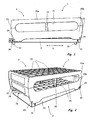
- FIG. 1 schematically shows a rack device 1 according to the invention, comprising a rack 2 and a rack slide 3, which according to the invention are firmly connected to each other by means of a releasable tool locking device.
- the rack 2 is in the illustrated embodiment of two parts made of plastic with an upper part 20a and a lower part 20b, which are fixedly connected to each other, for example glued and / or welded.
- the upper part 20a and the lower part 20b are connected to one another in such a way that a recessed grip 21 remains for easy handling of the upper 2.
- webs 22 are provided between the upper part 20a and the lower part 20b.
- locking grooves 24 are provided on end surfaces 23 of the deck, which are open in the illustrated embodiment, in each case in the direction of the end surfaces 23.
- the locking grooves 24 are placed on locking pins 30, 31 of the rack slide.
- the locking bolts 30, 31 protrude in the illustrated embodiment from an outer side of the rack slide 3.
- the associated rack 2 can be placed on the rack slide 3 such that inner sides of the lower part 20b are opposite the outer sides of the rack slide 3.
- the latching grooves 24 and the latching pins 30, 31 are spaced in pairs in the longitudinal direction L of the rack device 1.
- a direction in which the rack device 1 is inserted into a sample distribution system (not shown) is designated as the longitudinal direction L.
- the arrangement of the locking pins 30, 31 on these side surfaces a particularly simple handling is realized.
- latching bolts 30, 31 and associated latching grooves 24 are provided on end faces of the rack device 1.
- the locking pin 30 is movably mounted.
- the locking pin 30 itself elastically deformable, so that the force element is integrally formed with the locking pin.
- FIG. 1 shown schematically To connect the rack 2 with the latching slide 3 is first, as in FIG. 1 shown schematically, the rack 2 is guided with its locking groove 24 on the movable locking pin 30.
- the movable locking pin 30 can then be moved in the longitudinal direction L with the rack 2 inserted thereon until insertion of the locking groove 24 on the rigidly arranged locking pin 31 is possible.
- the locking pin 30 in the in FIG. 1 shown latching position by means of a force element, in particular by means of a spring held. A manufacture or release of the latching connection is thus possible only by overcoming the force applied by the spring force.
- the rack slide 3 has coupling elements 32, which are formed in the illustrated embodiment as positioning pins. With these coupling elements 32 of the rack slide 3 with corresponding elements of the sample distribution system, not shown, can be connected.
- the rack slide 3 is preferably made of a magnetic and / or a magnetizable material, so that a coupling of the rack carriage 3 with the sample distribution system is also possible by means of magnetic force.
- FIG. 2 schematically shows the rack device 1 according to FIG. 1 in a perspective view.
- the upper part 20a and the lower part 20b respectively recordings 25, 26, in which in FIG. 2 Sample carriers, not shown, in particular sample tubes, can be used.
- the rack slide 3 is formed as a substantially U-shaped part having a rectangular base. The rack 2 can be placed on the rack slide 3 such that the inner surfaces 27 of the lower part 20b come to lie on outer sides 33 of the flanks of the rack carriage 3.
- FIG. 3 schematically shows a sectional side view of a rack device according to FIG. 1 with three sample carriers 4a, 4b and 4c received therein.
- inserts 5 are used with spring arms 50 in the illustrated embodiment, through which the sample carrier 4a, 4b, 4c are held securely in the receptacles 25.
- the receptacles 26 are conically shaped in the lower part 20b, wherein the diameter of the receptacles 26 is formed gradually tapering downwards.
- FIG. 4 schematically shows a sectional view of the rack device 1 along a section line IV-IV according to FIG. 3 , As in FIG. 4 can be seen, the rack slide 3 has a fastening device 34. On the fastening device 34 formed as leaf springs 6 force elements are fixed, by which the movable locking pins 30 are forced into the locking position.
- receptacles 25 and 26 are provided, which are arranged in rows and columns, wherein five columns are provided, in each of which ten receptacles 25, 26 are formed.
- embodiments with a different column and / or row numbers are also conceivable.
- embodiments are preferred which have five columns, wherein four, five, ten, fifteen or even thirty rows can be provided.
- any other configurations are conceivable.
- FIG. 5 schematically shows a rack 2 according to a second embodiment of the invention, wherein receptacles 25, 26 are provided in thirty rows with five receptacles 25, 26.
- the rack device 1 according to FIG. 5 corresponds essentially to the rack device 1 according to the FIGS. 1 to 4 , Uniform reference symbols are used for the same components and a detailed description of these components will be omitted. Due to the increased length in the longitudinal direction L, the number of connecting webs 22 between the upper part 20a and the lower part 20b is increased to improve the stability.
- FIG. 6 schematically shows in a perspective view of another embodiment of a rack 2, wherein only four rows of receptacles 25, 26 are provided.
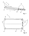
- FIGS. 7 and 8 schematically show a rack slide 3 for a rack device according to the invention, wherein in FIG. 7 for a better illustration the leaf springs 6 are not shown.
- the rack slide 3 has a fastening device 34 to which leaf springs 6 are attached in such a way that latching pins 30 connected to the leaf springs 6 are guided into a slot 35 provided on the side flanks 33 of the rack slide 3.
- the latching device By means of the latching device according to the invention, it is possible to connect a rack 2 in a simple manner and without tools to an associated rack slide 3.
- a plurality of rack slides 3 and / or rack devices 1 in a small space for example in a drawer or an input area of a Probenverteilsystems close together, next to each other and in series, without hindering handling of the rack device 1 for making or releasing the locking connection.
Landscapes
- Chemical & Material Sciences (AREA)
- Chemical Kinetics & Catalysis (AREA)
- Health & Medical Sciences (AREA)
- Analytical Chemistry (AREA)
- Physics & Mathematics (AREA)
- Life Sciences & Earth Sciences (AREA)
- Clinical Laboratory Science (AREA)
- Biochemistry (AREA)
- General Health & Medical Sciences (AREA)
- General Physics & Mathematics (AREA)
- Immunology (AREA)
- Pathology (AREA)
- Automatic Analysis And Handling Materials Therefor (AREA)
- Sampling And Sample Adjustment (AREA)
Claims (10)
- Dispositif de support pour une unité de distribution d'échantillons, comprenant un support (2) avec des logements pour des porte-échantillons (4a, 4b, 4c) et un chariot de support (3), dans lequel- le chariot de support (3) et le support (2) peuvent être solidarisés l'un à l'autre au moyen d'un dispositif d'encliquetage séparable sans outil,- dans lequel le dispositif d'encliquetage présente des éléments d'encliquetage complémentaires l'un à l'autre (30, 31, 24) disposés sur le chariot de support (3) et sur le support (2) et au moins un élément de force (6) pour appliquer une contrainte forcée, dans lequel une liaison par encliquetage peut être réalisée ou séparée par un mouvement relatif entre le chariot de support (3) et le support (2) contre la contrainte forcée,- dans lequel les éléments d'encliquetage comprennent au moins une paire de boulons d'arrêt (30, 31), comprenant un boulon d'arrêt fixe (31) et un boulon d'arrêt mobile (30) espacé de celui-ci, et des rainures d'encliquetage (24), dans lesquelles les boulons d'arrêt (30, 31) peuvent être engagés, dans lequel une distance des boulons d'arrêt (30, 31) peut être modifiée contre la contrainte forcée dudit au moins un élément de force (6).
- Dispositif de support selon la revendication 1, caractérisé en ce que les éléments d'encliquetage comprennent au moins une paire de rainures d'encliquetage (24) complémentaire à la paire de boulons d'arrêt (30, 31), avec au moins deux faces actives opposées l'une à l'autre, dans lequel ledit au moins un élément de force (6) pousse la paire de boulons d'arrêt (30, 31) sur les faces actives lors d'une liaison par encliquetage.
- Dispositif de support selon la revendication 1 ou 2, caractérisé en ce qu'il est prévu respectivement une paire de boulons d'arrêt (30, 31) sur des faces latérales opposées (33) du chariot de support (3), dans lequel les boulons d'arrêt (30, 31) sont disposés à distance l'un de l'autre en direction longitudinale (L).
- Dispositif de support selon la revendication 3, caractérisé en ce qu'il est prévu respectivement une paire de rainures d'encliquetage (24) sur des faces latérales du support (2), dans lesquelles une paire de boulons d'arrêt (30, 31) s'engage pour une liaison par encliquetage.
- Dispositif de support selon l'une quelconque des revendications 1 à 4, caractérisé en ce que des éléments (5) avec des bras de ressort élastiques (50) sont insérés dans les logements pour maintenir les porte-échantillons (4a, 4b, 4c).
- Dispositif de support selon l'une quelconque des revendications 1 à 5, caractérisé en ce que le support (2) est réalisé en une matière plastique incassable, en particulier en polycarbonate.
- Dispositif de support selon la revendication 6, caractérisé en ce que le support (2) est composé d'une partie supérieure (20a) et d'une partie inférieure (20b) solidarisée, en particulier soudée ou collée, à celle-ci.
- Dispositif de support selon la revendication 7, caractérisé en ce que la partie inférieure (20b) et la partie supérieure (20a) présentent des logements (25, 26) alignés les uns avec les autres pour des porte-échantillons (4a, 4b, 4c), dans lequel les logements (25, 26) de la partie inférieure (20b) sont de forme conique décroissante.
- Dispositif de support selon l'une quelconque des revendications 1 à 8, caractérisé en ce que le chariot de support (3) est réalisé au moins partiellement en un matériau magnétique et/ou magnétisable.
- Dispositif de support selon l'une quelconque des revendications 1 à 9, caractérisé en ce que le chariot de support (3) présente sur son côté inférieur des éléments de couplage, en particulier des goupilles de positionnement (32), pour le couplage à l'unité de distribution d'échantillons.
Applications Claiming Priority (2)
| Application Number | Priority Date | Filing Date | Title |
|---|---|---|---|
| DE200810058755 DE102008058755A1 (de) | 2008-11-14 | 2008-11-14 | Rackvorrichtung für ein Probenverteilsystem |
| PCT/EP2009/008028 WO2010054799A1 (fr) | 2008-11-14 | 2009-11-11 | Dispositif de rack pour un système de distribution d'échantillons |
Publications (3)
| Publication Number | Publication Date |
|---|---|
| EP2355932A1 EP2355932A1 (fr) | 2011-08-17 |
| EP2355932B1 true EP2355932B1 (fr) | 2014-02-12 |
| EP2355932B8 EP2355932B8 (fr) | 2014-04-09 |
Family
ID=41820465
Family Applications (1)
| Application Number | Title | Priority Date | Filing Date |
|---|---|---|---|
| EP09749030.4A Active EP2355932B8 (fr) | 2008-11-14 | 2009-11-11 | Support pour une unité d'échantillonnage |
Country Status (5)
| Country | Link |
|---|---|
| US (1) | US8940252B2 (fr) |
| EP (1) | EP2355932B8 (fr) |
| DE (1) | DE102008058755A1 (fr) |
| ES (1) | ES2457532T3 (fr) |
| WO (1) | WO2010054799A1 (fr) |
Families Citing this family (26)
| Publication number | Priority date | Publication date | Assignee | Title |
|---|---|---|---|---|
| US8703492B2 (en) | 2007-04-06 | 2014-04-22 | Qiagen Gaithersburg, Inc. | Open platform hybrid manual-automated sample processing system |
| US8357538B2 (en) * | 2007-04-06 | 2013-01-22 | Qiagen Gaithersburg, Inc. | Automated assay and system |
| US20130116597A1 (en) * | 2011-11-04 | 2013-05-09 | Phenomenex, Inc. | Method and apparatus for acquiring blood for testing |
| JP6425498B2 (ja) * | 2013-11-06 | 2018-11-21 | 協和メデックス株式会社 | 搬送装置、及び分析装置 |
| EP3283222B1 (fr) * | 2015-04-17 | 2025-02-19 | Neoteryx, LLC | Appareil de manipulation de sang pour analyse |
| US10071381B2 (en) | 2015-04-17 | 2018-09-11 | Neoteryx, Llc. | Method and apparatus for handling blood for testing |
| ES2920382T3 (es) | 2015-11-16 | 2022-08-03 | Beckman Coulter Inc | Gradilla para tubos de muestras y sistema de análisis de tubos de muestras |
| EP3211423A1 (fr) * | 2016-02-23 | 2017-08-30 | Siemens Healthcare Diagnostics Products GmbH | Appareil d'analyse automatique ayant des positions de reception pour le recipient de liquide |
| USD808540S1 (en) | 2016-07-28 | 2018-01-23 | Beckman Coulter, Inc. | Sample tube rack |
| USD812243S1 (en) | 2016-07-28 | 2018-03-06 | Beckman Coulter, Inc. | Sample tube rack |
| EP3330713A1 (fr) | 2016-12-01 | 2018-06-06 | Roche Diagniostics GmbH | Système de gestion de laboratoire et système d'automatisation de laboratoire |
| USD938612S1 (en) | 2017-06-16 | 2021-12-14 | Beckman Coulter, Inc. | Sample rack |
| EP3639040B1 (fr) | 2017-06-16 | 2024-02-21 | Beckman Coulter, Inc. | Dispositif et procédé pour la manutention de tubes de test |
| US10694922B1 (en) * | 2018-04-25 | 2020-06-30 | 4 R Oceans, LLC | Drinking straw cleaning caddy |
| USD966550S1 (en) | 2019-04-02 | 2022-10-11 | DePuy Synthes Products, Inc. | Storage rack for sterile packaging |
| USD1002869S1 (en) | 2019-04-02 | 2023-10-24 | DePuy Synthes Products, Inc. | Storage rack for sterile packaging |
| USD930852S1 (en) * | 2019-04-02 | 2021-09-14 | DePuy Synthes Products, Inc. | Storage rack for sterile packaging |
| US11083295B2 (en) | 2019-04-02 | 2021-08-10 | DePuy Synthes Products, Inc. | Tube rack apparatus |
| USD925767S1 (en) | 2019-04-02 | 2021-07-20 | DePuy Synthes Products, Inc. | Storage rack for sterile packaging |
| CN110420677A (zh) * | 2019-09-02 | 2019-11-08 | 华东师范大学 | 一种高度可调用于富集分离痕量元素的工作台 |
| EP3789772B1 (fr) | 2019-09-05 | 2025-03-26 | Roche Diagnostics GmbH | Procédé de détermination d'une position de portoir sur une unité de placement de portoir d'un système de manipulation de laboratoire et système de manipulation de laboratoire |
| US11642677B2 (en) * | 2019-12-05 | 2023-05-09 | QIS, Inc. | Split microplate and vials |
| EP3862094A1 (fr) | 2020-02-10 | 2021-08-11 | Roche Diagnostics GmbH | Adaptateur pour un support de récipients d'échantillons et dispositif de support de récipients d'échantillons |
| US11786907B2 (en) * | 2020-11-21 | 2023-10-17 | Mercy Bioanalytics, Inc. | Column tube holder for improved-accuracy assays |
| USD959924S1 (en) * | 2021-04-21 | 2022-08-09 | Guangzhou Shengjisong International Trade Co., Ltd. | Flipping egg holder |
| WO2025132629A1 (fr) | 2023-12-20 | 2025-06-26 | Roche Diagnostics Gmbh | Support de tube à échantillon, dispositif d'aide au montage, et système de transport de tube à échantillon |
Family Cites Families (12)
| Publication number | Priority date | Publication date | Assignee | Title |
|---|---|---|---|---|
| US3857606A (en) * | 1973-11-29 | 1974-12-31 | Everest & Jennings | Swing-away detachable wheelchair footrest |
| US5632388A (en) * | 1995-01-30 | 1997-05-27 | Forma Scientific, Inc. | Test tube rack assembly |
| US7141213B1 (en) | 1996-07-05 | 2006-11-28 | Beckman Coulter, Inc. | Automated sample processing system |
| US6193892B1 (en) * | 1999-03-03 | 2001-02-27 | Promega Corporation | Magnetic separation assembly and method |
| US6752967B2 (en) * | 2002-01-04 | 2004-06-22 | Dade Behring Inc. | Stackable aliquot vessel array |
| DE50202704D1 (de) * | 2002-01-22 | 2005-05-12 | Mpb Meltec Patent Und Beteilig | Verfahren und Vorrichtung für die Probenvorbereitung zur Analyse von biologischen Proben |
| DE20310332U1 (de) * | 2003-07-04 | 2004-11-11 | Mwg-Biotech Ag | Vorrichtung zum automatischen Öffnen und Schließen von Reaktionsgefäßen |
| JP2005233664A (ja) * | 2004-02-17 | 2005-09-02 | Ids:Kk | 試験管ラック |
| EP1655609B1 (fr) * | 2004-11-04 | 2013-09-18 | F.Hoffmann-La Roche Ag | Ensemble support d'eprouvettes comprenant une partie mouvant pour agiter d'échantillon |
| US7669721B2 (en) | 2005-12-01 | 2010-03-02 | Handi-Craft Company | Drying rack assembly for baby bottles |
| JP2007303960A (ja) | 2006-05-11 | 2007-11-22 | Olympus Corp | ラックトレイ |
| US7820115B2 (en) | 2007-05-30 | 2010-10-26 | Bel-Art Products, Inc. | Adjustable laboratory rack |
-
2008
- 2008-11-14 DE DE200810058755 patent/DE102008058755A1/de not_active Withdrawn
-
2009
- 2009-11-11 US US13/129,056 patent/US8940252B2/en active Active
- 2009-11-11 EP EP09749030.4A patent/EP2355932B8/fr active Active
- 2009-11-11 WO PCT/EP2009/008028 patent/WO2010054799A1/fr not_active Ceased
- 2009-11-11 ES ES09749030.4T patent/ES2457532T3/es active Active
Also Published As
| Publication number | Publication date |
|---|---|
| EP2355932A1 (fr) | 2011-08-17 |
| US20110274595A1 (en) | 2011-11-10 |
| EP2355932B8 (fr) | 2014-04-09 |
| WO2010054799A1 (fr) | 2010-05-20 |
| ES2457532T3 (es) | 2014-04-28 |
| DE102008058755A1 (de) | 2010-05-27 |
| US8940252B2 (en) | 2015-01-27 |
Similar Documents
| Publication | Publication Date | Title |
|---|---|---|
| WO2010054799A1 (fr) | Dispositif de rack pour un système de distribution d'échantillons | |
| EP3200654B1 (fr) | Dispositif de guidage | |
| EP2746634B1 (fr) | Support de cable avec un cadre en forme de U et prises multiples pour le passage de cables. | |
| EP2767828B1 (fr) | Dispositif de serrage pour le serrage de plusieurs colonnes pour un dispositif de préparation d'échantillon | |
| EP3613312A1 (fr) | Guide de tiroir | |
| EP3598188B1 (fr) | Accouplement permettant de former une connection optique | |
| DE20014492U1 (de) | Gleitschienenanordnung | |
| EP3909477A1 (fr) | Attache rideau | |
| EP2392286B1 (fr) | Unité de stockage de vis à os, ensemble et récipient chirurgical | |
| WO2023099243A1 (fr) | Entretoise pour maintenir espacés des supports de pointes de pipette qui sont empilés les uns sur les autres | |
| WO2017013114A1 (fr) | Maintien en position d'un catheter | |
| EP3699660A2 (fr) | Armoire de distribution dotée d'une entrée de tuyau vide permettant l'entrée d'une pluralité de câbles à fibre optique dans un espace intérieur d'armoire de distribution | |
| EP1809441B1 (fr) | Dispositif de serrage et de prehension, en particulier pince lineaire ou centrale | |
| DE102009009522A1 (de) | Umlenkkörper für einen Kugelgewindetrieb | |
| DE102017219983B4 (de) | Behältnisaufnahmevorrichtung für einen Fahrzeuginnenraum | |
| EP0022988B1 (fr) | Support pour récipients tubulaires | |
| DE102019108777A1 (de) | Einrichtung zum Fixieren von Knochen | |
| DE19827350A1 (de) | Vorrichtung zur verschiebbaren Montage eines Gegenstands, insbesondere einer Handbrause, an einer Tragstange | |
| DE2821893A1 (de) | Klammer, insbesondere chirurgische klammer | |
| EP1180607A1 (fr) | Pièce de serrage | |
| AT398890B (de) | Vorrichtung zur halterung und präsentation von warenpäckchen | |
| DE102012106865A1 (de) | Fixiervorrichtung für einen Ausstattungsgegenstand an einer Fixierschiene | |
| CH662159A5 (de) | Loesbare steckverbindung fuer einen stift in einer stecktafel. | |
| WO2014194981A1 (fr) | Élément de voie pour une installation de transport de récipients présentant un accouplement à encliquetage | |
| DE102014107150B4 (de) | Schraubstock |
Legal Events
| Date | Code | Title | Description |
|---|---|---|---|
| PUAI | Public reference made under article 153(3) epc to a published international application that has entered the european phase |
Free format text: ORIGINAL CODE: 0009012 |
|
| 17P | Request for examination filed |
Effective date: 20110530 |
|
| AK | Designated contracting states |
Kind code of ref document: A1 Designated state(s): AT BE BG CH CY CZ DE DK EE ES FI FR GB GR HR HU IE IS IT LI LT LU LV MC MK MT NL NO PL PT RO SE SI SK SM TR |
|
| DAX | Request for extension of the european patent (deleted) | ||
| GRAP | Despatch of communication of intention to grant a patent |
Free format text: ORIGINAL CODE: EPIDOSNIGR1 |
|
| INTG | Intention to grant announced |
Effective date: 20130821 |
|
| GRAS | Grant fee paid |
Free format text: ORIGINAL CODE: EPIDOSNIGR3 |
|
| GRAA | (expected) grant |
Free format text: ORIGINAL CODE: 0009210 |
|
| AK | Designated contracting states |
Kind code of ref document: B1 Designated state(s): AT BE BG CH CY CZ DE DK EE ES FI FR GB GR HR HU IE IS IT LI LT LU LV MC MK MT NL NO PL PT RO SE SI SK SM TR |
|
| RAP1 | Party data changed (applicant data changed or rights of an application transferred) |
Owner name: ROCHE PVT GMBH |
|
| REG | Reference to a national code |
Ref country code: GB Ref legal event code: FG4D Free format text: NOT ENGLISH |
|
| REG | Reference to a national code |
Ref country code: CH Ref legal event code: EP |
|
| REG | Reference to a national code |
Ref country code: AT Ref legal event code: REF Ref document number: 651888 Country of ref document: AT Kind code of ref document: T Effective date: 20140215 |
|
| RAP2 | Party data changed (patent owner data changed or rights of a patent transferred) |
Owner name: F.HOFFMANN-LA ROCHE AG Owner name: ROCHE DIAGNOSTICS GMBH |
|
| REG | Reference to a national code |
Ref country code: IE Ref legal event code: FG4D Free format text: LANGUAGE OF EP DOCUMENT: GERMAN |
|
| REG | Reference to a national code |
Ref country code: DE Ref legal event code: R096 Ref document number: 502009008785 Country of ref document: DE Effective date: 20140327 |
|
| REG | Reference to a national code |
Ref country code: ES Ref legal event code: FG2A Ref document number: 2457532 Country of ref document: ES Kind code of ref document: T3 Effective date: 20140428 |
|
| REG | Reference to a national code |
Ref country code: NL Ref legal event code: VDEP Effective date: 20140212 |
|
| REG | Reference to a national code |
Ref country code: LT Ref legal event code: MG4D |
|
| PG25 | Lapsed in a contracting state [announced via postgrant information from national office to epo] |
Ref country code: NO Free format text: LAPSE BECAUSE OF FAILURE TO SUBMIT A TRANSLATION OF THE DESCRIPTION OR TO PAY THE FEE WITHIN THE PRESCRIBED TIME-LIMIT Effective date: 20140512 Ref country code: LT Free format text: LAPSE BECAUSE OF FAILURE TO SUBMIT A TRANSLATION OF THE DESCRIPTION OR TO PAY THE FEE WITHIN THE PRESCRIBED TIME-LIMIT Effective date: 20140212 Ref country code: IS Free format text: LAPSE BECAUSE OF FAILURE TO SUBMIT A TRANSLATION OF THE DESCRIPTION OR TO PAY THE FEE WITHIN THE PRESCRIBED TIME-LIMIT Effective date: 20140612 |
|
| PG25 | Lapsed in a contracting state [announced via postgrant information from national office to epo] |
Ref country code: PT Free format text: LAPSE BECAUSE OF FAILURE TO SUBMIT A TRANSLATION OF THE DESCRIPTION OR TO PAY THE FEE WITHIN THE PRESCRIBED TIME-LIMIT Effective date: 20140612 Ref country code: SE Free format text: LAPSE BECAUSE OF FAILURE TO SUBMIT A TRANSLATION OF THE DESCRIPTION OR TO PAY THE FEE WITHIN THE PRESCRIBED TIME-LIMIT Effective date: 20140212 Ref country code: NL Free format text: LAPSE BECAUSE OF FAILURE TO SUBMIT A TRANSLATION OF THE DESCRIPTION OR TO PAY THE FEE WITHIN THE PRESCRIBED TIME-LIMIT Effective date: 20140212 Ref country code: FI Free format text: LAPSE BECAUSE OF FAILURE TO SUBMIT A TRANSLATION OF THE DESCRIPTION OR TO PAY THE FEE WITHIN THE PRESCRIBED TIME-LIMIT Effective date: 20140212 Ref country code: CY Free format text: LAPSE BECAUSE OF FAILURE TO SUBMIT A TRANSLATION OF THE DESCRIPTION OR TO PAY THE FEE WITHIN THE PRESCRIBED TIME-LIMIT Effective date: 20140212 |
|
| PG25 | Lapsed in a contracting state [announced via postgrant information from national office to epo] |
Ref country code: HR Free format text: LAPSE BECAUSE OF FAILURE TO SUBMIT A TRANSLATION OF THE DESCRIPTION OR TO PAY THE FEE WITHIN THE PRESCRIBED TIME-LIMIT Effective date: 20140212 Ref country code: LV Free format text: LAPSE BECAUSE OF FAILURE TO SUBMIT A TRANSLATION OF THE DESCRIPTION OR TO PAY THE FEE WITHIN THE PRESCRIBED TIME-LIMIT Effective date: 20140212 |
|
| PG25 | Lapsed in a contracting state [announced via postgrant information from national office to epo] |
Ref country code: EE Free format text: LAPSE BECAUSE OF FAILURE TO SUBMIT A TRANSLATION OF THE DESCRIPTION OR TO PAY THE FEE WITHIN THE PRESCRIBED TIME-LIMIT Effective date: 20140212 Ref country code: CZ Free format text: LAPSE BECAUSE OF FAILURE TO SUBMIT A TRANSLATION OF THE DESCRIPTION OR TO PAY THE FEE WITHIN THE PRESCRIBED TIME-LIMIT Effective date: 20140212 Ref country code: RO Free format text: LAPSE BECAUSE OF FAILURE TO SUBMIT A TRANSLATION OF THE DESCRIPTION OR TO PAY THE FEE WITHIN THE PRESCRIBED TIME-LIMIT Effective date: 20140212 Ref country code: DK Free format text: LAPSE BECAUSE OF FAILURE TO SUBMIT A TRANSLATION OF THE DESCRIPTION OR TO PAY THE FEE WITHIN THE PRESCRIBED TIME-LIMIT Effective date: 20140212 |
|
| REG | Reference to a national code |
Ref country code: DE Ref legal event code: R097 Ref document number: 502009008785 Country of ref document: DE |
|
| PG25 | Lapsed in a contracting state [announced via postgrant information from national office to epo] |
Ref country code: SK Free format text: LAPSE BECAUSE OF FAILURE TO SUBMIT A TRANSLATION OF THE DESCRIPTION OR TO PAY THE FEE WITHIN THE PRESCRIBED TIME-LIMIT Effective date: 20140212 Ref country code: PL Free format text: LAPSE BECAUSE OF FAILURE TO SUBMIT A TRANSLATION OF THE DESCRIPTION OR TO PAY THE FEE WITHIN THE PRESCRIBED TIME-LIMIT Effective date: 20140212 |
|
| PLBE | No opposition filed within time limit |
Free format text: ORIGINAL CODE: 0009261 |
|
| STAA | Information on the status of an ep patent application or granted ep patent |
Free format text: STATUS: NO OPPOSITION FILED WITHIN TIME LIMIT |
|
| 26N | No opposition filed |
Effective date: 20141113 |
|
| REG | Reference to a national code |
Ref country code: DE Ref legal event code: R097 Ref document number: 502009008785 Country of ref document: DE Effective date: 20141113 |
|
| PG25 | Lapsed in a contracting state [announced via postgrant information from national office to epo] |
Ref country code: SI Free format text: LAPSE BECAUSE OF FAILURE TO SUBMIT A TRANSLATION OF THE DESCRIPTION OR TO PAY THE FEE WITHIN THE PRESCRIBED TIME-LIMIT Effective date: 20140212 |
|
| PG25 | Lapsed in a contracting state [announced via postgrant information from national office to epo] |
Ref country code: LU Free format text: LAPSE BECAUSE OF FAILURE TO SUBMIT A TRANSLATION OF THE DESCRIPTION OR TO PAY THE FEE WITHIN THE PRESCRIBED TIME-LIMIT Effective date: 20141111 Ref country code: BE Free format text: LAPSE BECAUSE OF NON-PAYMENT OF DUE FEES Effective date: 20141130 Ref country code: MC Free format text: LAPSE BECAUSE OF FAILURE TO SUBMIT A TRANSLATION OF THE DESCRIPTION OR TO PAY THE FEE WITHIN THE PRESCRIBED TIME-LIMIT Effective date: 20140212 |
|
| REG | Reference to a national code |
Ref country code: IE Ref legal event code: MM4A |
|
| REG | Reference to a national code |
Ref country code: FR Ref legal event code: PLFP Year of fee payment: 7 |
|
| PG25 | Lapsed in a contracting state [announced via postgrant information from national office to epo] |
Ref country code: IE Free format text: LAPSE BECAUSE OF NON-PAYMENT OF DUE FEES Effective date: 20141111 |
|
| PG25 | Lapsed in a contracting state [announced via postgrant information from national office to epo] |
Ref country code: SM Free format text: LAPSE BECAUSE OF FAILURE TO SUBMIT A TRANSLATION OF THE DESCRIPTION OR TO PAY THE FEE WITHIN THE PRESCRIBED TIME-LIMIT Effective date: 20140212 |
|
| PG25 | Lapsed in a contracting state [announced via postgrant information from national office to epo] |
Ref country code: BG Free format text: LAPSE BECAUSE OF FAILURE TO SUBMIT A TRANSLATION OF THE DESCRIPTION OR TO PAY THE FEE WITHIN THE PRESCRIBED TIME-LIMIT Effective date: 20140212 Ref country code: GR Free format text: LAPSE BECAUSE OF FAILURE TO SUBMIT A TRANSLATION OF THE DESCRIPTION OR TO PAY THE FEE WITHIN THE PRESCRIBED TIME-LIMIT Effective date: 20140513 |
|
| PG25 | Lapsed in a contracting state [announced via postgrant information from national office to epo] |
Ref country code: MT Free format text: LAPSE BECAUSE OF FAILURE TO SUBMIT A TRANSLATION OF THE DESCRIPTION OR TO PAY THE FEE WITHIN THE PRESCRIBED TIME-LIMIT Effective date: 20140212 Ref country code: TR Free format text: LAPSE BECAUSE OF FAILURE TO SUBMIT A TRANSLATION OF THE DESCRIPTION OR TO PAY THE FEE WITHIN THE PRESCRIBED TIME-LIMIT Effective date: 20140212 Ref country code: HU Free format text: LAPSE BECAUSE OF FAILURE TO SUBMIT A TRANSLATION OF THE DESCRIPTION OR TO PAY THE FEE WITHIN THE PRESCRIBED TIME-LIMIT; INVALID AB INITIO Effective date: 20091111 |
|
| REG | Reference to a national code |
Ref country code: FR Ref legal event code: PLFP Year of fee payment: 8 |
|
| REG | Reference to a national code |
Ref country code: FR Ref legal event code: PLFP Year of fee payment: 9 |
|
| PG25 | Lapsed in a contracting state [announced via postgrant information from national office to epo] |
Ref country code: MK Free format text: LAPSE BECAUSE OF FAILURE TO SUBMIT A TRANSLATION OF THE DESCRIPTION OR TO PAY THE FEE WITHIN THE PRESCRIBED TIME-LIMIT Effective date: 20140212 |
|
| REG | Reference to a national code |
Ref country code: FR Ref legal event code: PLFP Year of fee payment: 10 |
|
| REG | Reference to a national code |
Ref country code: CH Ref legal event code: U11 Free format text: ST27 STATUS EVENT CODE: U-0-0-U10-U11 (AS PROVIDED BY THE NATIONAL OFFICE) Effective date: 20251201 |
|
| PGFP | Annual fee paid to national office [announced via postgrant information from national office to epo] |
Ref country code: DE Payment date: 20251022 Year of fee payment: 17 |
|
| PGFP | Annual fee paid to national office [announced via postgrant information from national office to epo] |
Ref country code: GB Payment date: 20251023 Year of fee payment: 17 |
|
| PGFP | Annual fee paid to national office [announced via postgrant information from national office to epo] |
Ref country code: AT Payment date: 20251024 Year of fee payment: 17 |
|
| PGFP | Annual fee paid to national office [announced via postgrant information from national office to epo] |
Ref country code: IT Payment date: 20251022 Year of fee payment: 17 |
|
| PGFP | Annual fee paid to national office [announced via postgrant information from national office to epo] |
Ref country code: FR Payment date: 20251022 Year of fee payment: 17 |
|
| PGFP | Annual fee paid to national office [announced via postgrant information from national office to epo] |
Ref country code: CH Payment date: 20251201 Year of fee payment: 17 |
|
| PGFP | Annual fee paid to national office [announced via postgrant information from national office to epo] |
Ref country code: ES Payment date: 20251201 Year of fee payment: 17 |