EP2356005B2 - Dispositif de commande pour un équipement de traitement d'air comprimé d'un véhicule, équipement de traitement d'air comprimé, système de véhicule, véhicule et procédé de commande - Google Patents
Dispositif de commande pour un équipement de traitement d'air comprimé d'un véhicule, équipement de traitement d'air comprimé, système de véhicule, véhicule et procédé de commande Download PDFInfo
- Publication number
- EP2356005B2 EP2356005B2 EP09777770.0A EP09777770A EP2356005B2 EP 2356005 B2 EP2356005 B2 EP 2356005B2 EP 09777770 A EP09777770 A EP 09777770A EP 2356005 B2 EP2356005 B2 EP 2356005B2
- Authority
- EP
- European Patent Office
- Prior art keywords
- compressed air
- control device
- vehicle
- phases
- regeneration
- Prior art date
- Legal status (The legal status is an assumption and is not a legal conclusion. Google has not performed a legal analysis and makes no representation as to the accuracy of the status listed.)
- Active
Links
Images
Classifications
-
- B—PERFORMING OPERATIONS; TRANSPORTING
- B60—VEHICLES IN GENERAL
- B60T—VEHICLE BRAKE CONTROL SYSTEMS OR PARTS THEREOF; BRAKE CONTROL SYSTEMS OR PARTS THEREOF, IN GENERAL; ARRANGEMENT OF BRAKING ELEMENTS ON VEHICLES IN GENERAL; PORTABLE DEVICES FOR PREVENTING UNWANTED MOVEMENT OF VEHICLES; VEHICLE MODIFICATIONS TO FACILITATE COOLING OF BRAKES
- B60T17/00—Component parts, details, or accessories of power brake systems not covered by groups B60T8/00, B60T13/00 or B60T15/00, or presenting other characteristic features
- B60T17/002—Air treatment devices
- B60T17/004—Draining and drying devices
-
- B—PERFORMING OPERATIONS; TRANSPORTING
- B01—PHYSICAL OR CHEMICAL PROCESSES OR APPARATUS IN GENERAL
- B01D—SEPARATION
- B01D53/00—Separation of gases or vapours; Recovering vapours of volatile solvents from gases; Chemical or biological purification of waste gases, e.g. engine exhaust gases, smoke, fumes, flue gases, aerosols
- B01D53/02—Separation of gases or vapours; Recovering vapours of volatile solvents from gases; Chemical or biological purification of waste gases, e.g. engine exhaust gases, smoke, fumes, flue gases, aerosols by adsorption, e.g. preparative gas chromatography
- B01D53/04—Separation of gases or vapours; Recovering vapours of volatile solvents from gases; Chemical or biological purification of waste gases, e.g. engine exhaust gases, smoke, fumes, flue gases, aerosols by adsorption, e.g. preparative gas chromatography with stationary adsorbents
- B01D53/0454—Controlling adsorption
-
- B—PERFORMING OPERATIONS; TRANSPORTING
- B01—PHYSICAL OR CHEMICAL PROCESSES OR APPARATUS IN GENERAL
- B01D—SEPARATION
- B01D53/00—Separation of gases or vapours; Recovering vapours of volatile solvents from gases; Chemical or biological purification of waste gases, e.g. engine exhaust gases, smoke, fumes, flue gases, aerosols
- B01D53/26—Drying gases or vapours
- B01D53/261—Drying gases or vapours by adsorption
-
- B—PERFORMING OPERATIONS; TRANSPORTING
- B60—VEHICLES IN GENERAL
- B60T—VEHICLE BRAKE CONTROL SYSTEMS OR PARTS THEREOF; BRAKE CONTROL SYSTEMS OR PARTS THEREOF, IN GENERAL; ARRANGEMENT OF BRAKING ELEMENTS ON VEHICLES IN GENERAL; PORTABLE DEVICES FOR PREVENTING UNWANTED MOVEMENT OF VEHICLES; VEHICLE MODIFICATIONS TO FACILITATE COOLING OF BRAKES
- B60T17/00—Component parts, details, or accessories of power brake systems not covered by groups B60T8/00, B60T13/00 or B60T15/00, or presenting other characteristic features
- B60T17/18—Safety devices; Monitoring
- B60T17/22—Devices for monitoring or checking brake systems; Signal devices
- B60T17/221—Procedure or apparatus for checking or keeping in a correct functioning condition of brake systems
-
- B—PERFORMING OPERATIONS; TRANSPORTING
- B01—PHYSICAL OR CHEMICAL PROCESSES OR APPARATUS IN GENERAL
- B01D—SEPARATION
- B01D2259/00—Type of treatment
- B01D2259/45—Gas separation or purification devices adapted for specific applications
- B01D2259/4566—Gas separation or purification devices adapted for specific applications for use in transportation means
Definitions
- the invention relates to a control device for a compressed air processing device of a vehicle, a corresponding compressed air processing device and a method for controlling the compressed air processing device.
- a compressed air processing device of a vehicle is generally connected to a compressor that is driven directly by the engine.
- the compressor can be arranged directly on the motor shaft and can therefore always be operated when the motor is rotating, or it can be coupled to the motor via a coupling.
- the compressor conveys compressed air, which first passes through an air dryer, which generally has drying granules as a drying agent and, if necessary, can also perform cleaning.
- the conveyed, dried compressed air is then stored in a compressed air reservoir and can be passed on to consumer circuits, which can be, for example, brake control circuits of pneumatic brake systems and / or pneumatic level controls with air bellows.
- the individual consumer circuits can initially again have compressed air reservoirs.
- a delivery phase or filling phase the moisture content of the air dryer is increased; In order to avoid oversaturation of the desiccant and lower its degree of humidity again, part of the dry compressed air stored in the compressed air reservoir is returned to the air dryer during the regeneration phases. B. released to the environment.
- These regeneration phases generally take place directly after a delivery phase, so that a fixed amount of air or a certain proportion of the previously delivered air amount is always used for the regeneration. The initiation of these regeneration phases can take place purely mechanically or also electrically by the control device.
- the compressed air system can thus be protected from harmful moisture, in particular also from condensation overnight and, if necessary, from freezing of the absorbed moisture with corresponding consequential damage.
- the EP 1 183 172 B1 describes a compressed air brake system in which the compressed air reservoir is charged beyond the normal target value in overrun phases in which the kinetic energy of the vehicle drives the engine and the connected compressor, as this additional compressed air delivery takes place without additional fuel consumption.
- the delivery phases in which the engine drives the compressor while consuming fuel can thus be shortened or avoided to the corresponding extent, so that the overall fuel consumption can be reduced.
- DE 10 2005 005 002 A1 describes a device and a method in which the energy consumption of a unit is adjusted as a function of a load on the drive motor, with the storage tank always being filled to an upper pressure value in the case of a compressed air brake when driving downhill.
- EP 1 414 687 B1 describes a device and a method in which the delivery phases and regeneration phases are set as a function of a current engine load and a current compressed air consumption.
- the invention is based on the object of creating a control device for a compressed air processing device, such a compressed air processing device, a vehicle system with a compressed air processing device and a corresponding method for operating such a compressed air processing device, with which a relatively low fuel consumption can be achieved and an adequate amount of compressed air is made available will.
- management of the engine load and / or the generation of compressed air can thus be carried out, in which the regeneration phases are included.
- a management of the engine utilization takes into account in particular the fuel consumption and can thus determine phases with lower and higher fuel consumption (per distance);
- the desiccant can be dried excessively, i.e. it can be set to a lower setpoint humidity level, so that in phases with a higher engine load no additional load is required on the engine for regeneration.
- overrun phases of the engine i.e. phases in which, when the engine is engaged, the engine torque generated by the kinetic energy of the vehicle is greater than the engine torque requested by the driver via the accelerator pedal, can be used to control the engine and the compressor To convey compressed air and to store it in the compressed air reservoir, so that part of this additionally conveyed compressed air can then be used to regenerate the desiccant.
- the energy available in overrun phases without additional fuel consumption can not only be used for additional compressed air storage, but also for excessive drying of the Air dryer are used.
- the invention is based on the knowledge that in an overrun phase, part of the kinetic energy of the vehicle can be stored in excessive drying of the drying agent of the air dryer, since otherwise the drying of the drying agent is associated with a certain amount of fuel consumption.
- the excessive regeneration can not only be carried out in or after an overrun phase, but also before the overrun phase, if this is known in advance.
- the compressed air reservoir is emptied through an additional regeneration phase to below the otherwise relevant setpoint pressure (e.g. to above a minimum reserve value), since a cost-effective replenishment is then possible in the overrun phase.
- sections of the route with higher compressed air consumption can be determined in advance and an excessive regeneration and, if necessary, an additional filling of the compressed air reservoir to a higher target pressure can be carried out in order to subsequently enable longer delivery and use phases.
- a regulation to a target humidity level can preferably be carried out, the target humidity level being determined by the control device and an actual value or current value either being determined directly by a measurement signal from a humidity sensor or being determined indirectly from the durations of the last delivery phases and regeneration phases or is estimated.
- the control device can thus set the setpoint humidity levels as a function of the future values of the engine load or the compressed air consumption.
- fuel can thus be saved. Furthermore, longer delivery phases or longer useful phases and a higher air consumption with fewer or shorter regeneration phases are possible. This means that the regeneration phases can be delayed or shortened. This leads, among other things, to a smoother control behavior and less frequent switching processes, in particular longer delivery phases are made possible. Furthermore, the components can optionally be made smaller.
- the route sections with different compressed air consumption and / or different engine loads can be determined in advance. This can be done on the one hand from map data or route data on the route ahead as well as position data, whereby the position data can be generated e.g. by a global position determination system (GPS) and / or a distance counter (odometer) of the vehicle. In this way, route profiles or route-dependent conveying profiles and / or route-dependent consumption profiles of the compressed air are created. In addition to or as an alternative to the determination from map data, this creation can also be carried out as an adaptive or self-learning determination when the vehicle drives the relevant route several times, e.g. on a regular bus or a shuttle-wagon between two fixed points. In principle, adaptive systems can be formed not only for identical, but also similar routes, for which purpose the route profiles determined can be compared with one another and assessed qualitatively.
- the route profiles can not only be assigned to the respective route, but also time data, in particular times of day, in order to determine the different traffic loads at the different times of the day, in particular in the morning, noon, afternoon, evening and night.
- days of the week can also be specified, for example.
- the determined route profiles can be continuously updated by averaging in order to also take into account temporary changes, e.g. due to construction sites, obstructions, etc.
- a vehicle energy management system can thus be formed that can optimize energy consumption in a current and flexible manner.
- the control device performs a switchover to a regeneration phase or the extension of an existing regeneration phase by outputting corresponding control signals, in particular to the valve devices for setting the respective phases.
- the method according to the invention corresponds to the application of the control device according to the invention.
- One advantage of the invention is that future, previously known vehicle conditions with increased air consumption, e.g. unhitching, maneuvering, stops with desiccant that has already been over-rained, can be approached so that these situations are not hindered or delayed by the desiccant being regenerated. This improves the compressed air supply and thus reduces the vehicle maneuvering time and / or the vehicle manufacturer can equip the vehicle with smaller pressure accumulators and thus save costs and space on the vehicle frame.
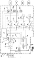
- a compressed air processing device 1 of a commercial vehicle 2 with vehicle engine 10 and pneumatic brakes and air springs has according to FIG Fig. 1 an electronic control device 3, directly or indirectly controls the operating state of a compressor 4 driven by the engine 10.
- the compressor 4 can, for example, be arranged directly on the motor shaft and be driven directly by the vehicle engine 10, or it can be driven by the vehicle engine 10 via a clutch.
- an engagement and disengagement of the compressor 4 from the engine 10 or, in the case of a rigid coupling of the compressor 4 to the engine 10, idling can be set without the delivery of compressed air.
- an air dryer 6 is connected, in which a drying agent 6a, for. B. a drying granulate is added.
- a compressed air delivery path 17 with a four-circuit protection valve 7 is connected via a check valve 16, which z. B. has four overflow valves 7a, 7b, 7c, 7d and to which in turn compressed air reservoirs 8, 18, 28, 38 of the four connected consumer circuits are connected; here is z. B. the container 8 for a service brake circuit I, the container 18 for a service brake circuit II, the container 28 for a trailer brake circuit and / or a parking brake circuit and the container 38 is provided for a secondary consumer circuit.
- a pressure limiting valve 7e and 7f can advantageously be provided in front of the containers 28 and 38.
- Pressure sensors 8a, 18a, 28a are provided in the containers 8, 18, 28 or at the compressed air supply to these containers, which output signals p1, p2, p3 to the control device 3.
- a check valve 9 in the blocking direction and a diaphragm 20 are connected to the outlet 6b of the air dryer 6, to which a regeneration path 21 is connected, which is thus blocked when the compressor 10 is in operation.
- a vent valve (flushing valve) 5 designed as a 2/2-way valve is connected between the output of the compressor 4 and a silencer 22 serving as a compressed air output; it has a pneumatic control input 5a which is connected to the regeneration path 21 and switches from the blocking position shown to the open position when pressure is applied.
- a compressor control solenoid valve 23 designed as a 3/2-way valve is connected between a pneumatic control input 4a of the compressor 4 and the silencer 22. In its rest position shown, the control input 4a is thus depressurized; when the compressor control solenoid valve 23 is activated via the control device 3, it places the delivery path 17 on the control input 4a, so that the compressor 4 is switched off.
- a regeneration control solenoid valve 24 is also designed as a 3/2-way valve and is connected between the regeneration path 21 and the silencer 22. In its de-energized basic state, it thus applies the regeneration path 21 to the silencer 22 so that the regeneration path 21 is pressureless when its control input is energized by the control device 3, it switches over and connects the regeneration path 21 to the conveying path 17.
- an electronic compressed air processing device 1 is implemented as a structural unit with components 3, 5, 6, 7, 8a, 9, 12, 16, 17, 18a, 20, 21, 22, 23, 24, 28a.
- This compressed air processing device 1 forms a vehicle system 30 with the compressor 4 and the compressed air tanks 8, 18, 28, 38.
- the compressor 4 conveys compressed air through the air dryer 6 and the four-circuit protection valve 7 to the compressed air tanks 8, 18, 28, 38.
- the control device 3 controls the regeneration control solenoid valve 24 so that it switches over and outputs compressed air from the compressed air reservoirs 8, 18, 28, 38 via the four-circuit protection valve 7 and the conveying path 17 to the regeneration path 21. Furthermore, the control device 3 switches the compressor control solenoid valve 23 so that it pressurizes the control input 4a of the control device 4 with compressed air and thus switches it off. Furthermore, the vent valve 5 is automatically switched over by the pressurized regeneration path 21 and thus places the compressor outlet or the inlet of the air dryer 6 on the silencer 22 so that they are depressurized. Since the outlet 6a of the air dryer 6 is also depressurized, the check valve 9 switches through, so that when the check valve 16 is blocked, the air dryer 6 is flushed through in the regeneration direction to the silencer 22 and thus to the environment.
- the compressed air received is dried in the air dryer 6 (and, if necessary, cleaned), as a result of which the degree of humidity in the air dryer 6 increases.
- the moisture absorbed in the air dryer 6 is completely or partially released again.
- the control device 3 can compare current pressure values determined from the pressure signals p1, p2, p3 with a setpoint pressure ps and, if the value falls below a limit value, switch from a regeneration phase to a delivery phase.
- a humidity sensor 12 z. B. be provided in the air dryer 6 or in a line connected to the air dryer 6, which outputs a measurement signal f of the degree of humidity to the control device 3.
- a humidity sensor 12 is not necessary, since the control device 3 can also automatically estimate the moisture content of the air dryer 6, e.g. B. from the duration of the previous funding phases and regeneration phases, the engine speed and other vehicle data.
- the moisture content of the air dryer 6 is set not only on the basis of the determined or estimated current moisture content, but additionally as a function of firstly the engine utilization, in particular the available kinetic energy of the vehicle 2 and / or secondly an expected compressed air requirement.
- the compressor 4 is driven in time periods or route sections with low engine load in order to charge all or some of the pressure accumulators 8, 18, 28, 38 with a pressure higher than a normal target pressure.
- Such phases are in particular overrun phases Ts of commercial vehicle 2 or its engine 10, in which, when the engine clutch is engaged, the overrun torque exerted on engine 10 by the kinetic energy of commercial vehicle 2 is greater than an engine torque requested by the driver or a vehicle dynamics control.
- Such overrun phases Ts can in particular be downhill journeys of the utility vehicle 2 and / or braking processes.
- braking of the commercial vehicle 2 is achieved via the engine and the connected compressor 4 and a higher pressure setpoint ps of some or all of the pressure accumulators 8, 18, 28, 38 is set in a delivery phase and this is thus excessively filled, with the pressure p, however, below an upper one Safety limit value remains.
- Overrun phases can currently be determined from a throttle valve position of the engine 10 and / or an actuation of the accelerator pedal and / or a data signal describing the engine torque on the vehicle bus of the vehicle 2.
- the additionally stored compressed air can be used on the one hand via the consumer circuits connected to the compressed air reservoirs 8, 18, 28, 38. According to the invention, this or part of this additional stored compressed air can also be used in addition to excessive drying of the desiccant 6a. In this way, a target humidity value is lowered and the degree of humidity f is lowered further in regeneration phases than in other phases. It is true that this excessive drying is possibly not appropriate in other phases in relation to the amount of compressed air required for this or the energy corresponding to the amount of compressed air, since the effectiveness or the further moisture removal by the compressed air that is introduced decreases as the degree of humidity decreases. According to the invention, however, it is recognized that there is an excess of kinetic energy available anyway and thus this kinetic energy or a part of this kinetic energy can be stored as excessive drying of the drying agent of the air dryer 6.
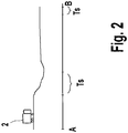
- Fig. 2 shows an example and schematically a route of a vehicle 2 between the start at A and the destination at B.
- one or more overrun phases Ts are present.
- An additional regeneration phase or the extension of a regeneration phase can thus be carried out via the control device 3 in an overrun phase Ts if an overrun phase has been recognized.
- the connected consumer circuits can consume compressed air at any time.
- any switching state of the compressed air preparation i.e. conveying, regenerating or idling, can basically be used at the same time.
- the relevant time periods or route sections with low engine load or overrun operation can already be determined in advance.
- this is possible by recording map data K and position data GPS, which are determined by a GPS system of utility vehicle 2.
- the control device 3 or a further device of the control system according to the invention that interacts with the control device 3 can determine anticipated overrun phases Ts and carry out the excessive drying of the drying agent 6a according to the invention in these.
- Gradient stretches with a not too steep slope, a transition from the motorway or expressway to slower roads and the end section before destination B can be recognized as overrun phases from the map data K.
- these can also be determined adaptively or in a self-learning manner if the commercial vehicle repeatedly drives two routes or parts of routes. This is particularly the case with buses and regular trucks that drive certain journeys, e.g. B. trucks in shuttle traffic, advantageous.
- route sections with different engine utilization can be determined in advance.
- These route sections can in particular be downhill journeys with a steep incline and stop-and-go sections in which a greater need for braking occurs.
- the end phase of the route can be assessed as a period of time with an increased demand for compressed air, which occurs as a result of braking, unsaddling, saddling and buckling processes in coaches.
- parking the vehicle with a larger amount of stored compressed air or higher air pressure in some or all of the compressed air reservoirs 8, 18, 28, 38 is recognized as advantageous so that this compressed air is available again during the subsequent journey to supply the consumer circuits accordingly under pressure to set and, if necessary, to carry out level adjustments.
- the aim is to achieve a maximum pressure in one, some or all of the compressed air reservoirs 8, 18, 28, 38 and, on the other hand, a very low degree of humidity in the air dryer 6.
- This determination of the route sections with a presumably increased compressed air requirement can also take place in accordance with the above statements from the map data K and position data GPS and / or adaptively. In particular the end of the journey is often entered directly into the GPS control system and is therefore known.
- a self-learning vehicle energy management system can create profiles of engine utilization and / or compressed air consumption not only for the same recurring routes, but also for routes recognized as similar or equivalent. For example, a route with corresponding upward and downward gradients and / or a classification as inner-city, country road or motorway is created and a consumption profile (performance requirement profile) and / or a regeneration profile is assigned to this sequence of the different areas.
- the energy management system according to the invention uses this information to optimize the flow of energy between the generators, ie the motor 10 including the compressor 4, the consumers of the connected consumer circuits and in one, some or all of the compressed air reservoirs 8, 18, 28, 38 as well as the device according to the invention for storing energy - Equivalent rated air dryer 6.
- the air dryer 6 is thus also viewed according to the invention as a kind of "energy store” and functionally integrated, since excessive drying creates an energy equivalent if the energy required for this is available in the system in sufficient quantities or in excess .
- a decision can be made according to the invention as to how one, several or all of the compressed air reservoirs 8, 18, 28, 38 are charged or refilled and, on the other hand, the humidity level of the air dryer 6 is set will.
- the creation of the profiles in the case of an adaptive method can take place by using minimum values, maximum values and average values from the different journeys.
- the profile can be improved or adapted to the changing environmental conditions through recurring journeys, e.g. with the help of moving average values. For example, traffic jams caused by temporary construction sites can also be recorded.
- times of day and / or days of the week can additionally be assigned to the route profiles.
- information about the state of charge or the mass of the commercial vehicle 2 can be used to determine the route profiles, some of which are already available on the vehicle-internal data bus, in order to better estimate the consumption profile and / or the regeneration profile of the route.
Landscapes
- Engineering & Computer Science (AREA)
- Transportation (AREA)
- Mechanical Engineering (AREA)
- Chemical & Material Sciences (AREA)
- Analytical Chemistry (AREA)
- General Chemical & Material Sciences (AREA)
- Oil, Petroleum & Natural Gas (AREA)
- Chemical Kinetics & Catalysis (AREA)
- Valves And Accessory Devices For Braking Systems (AREA)
- Vehicle Body Suspensions (AREA)
- Fluid-Pressure Circuits (AREA)
Claims (17)
- Dispositif de commande (3) pour un dispositif (1) de préparation d'air comprimé sur un véhicule (2),le dispositif de commande (3) délivrant des signaux de sortie qui ajustent des phases de refoulement et des phases de régénération du dispositif (1) de préparation d'air comprimé,un compresseur (4) refoulant dans une phase de refoulement de l'air comprimé vers au moins une réserve (8, 18, 28, 38) d'air comprimé à travers un sécheur d'air (6) présentant un moyen de séchage (6a) etde l'air comprimé provenant de la ou des réserves (8, 18, 28, 38) d'air comprimé étant amené dans une phase de régénération au séchage du moyen de séchage (6a) à travers le sécheur d'air (6),
caractérisé en ce quele dispositif de commande (3) établit des phases de régénération en fonction du taux d'utilisation futur du moteur et/ou de la consommation future du véhicule (2) en air comprimé. - Dispositif de commande selon la revendication 1, caractérisé en ce qu'il détermine à tout instant le taux d'humidité du moyen de séchage (6a) du sécheur d'air (6) et ajuste le taux d'humidité en délivrant des signaux de commande qui ajustent les phases de refoulement et les phases de régénération à un taux d'humidité de consigne.
- Dispositif de commande selon la revendication 2, caractérisé en ce qu'il détermine à tout instant le taux d'humidité à partir d'un signal (f) de mesure d'humidité d'un capteur d'humidité (12) présent dans le sécheur d'air (6) ou à l'extérieur du sécheur d'air et/ou par détermination des débits d'air des phases précédentes de refoulement et de régénération.
- Dispositif de commande selon les revendications 2 ou 3, caractérisé en ce qu'il détermine le taux d'humidité de consigne en fonction d'une valeur prédéterminée et/ou en tenant compte de du taux d'utilisation actuel ou futur du moteur et/ou de la consommation actuelle ou future du véhicule (2) en air comprimé.
- Dispositif de commande selon la revendication 4, caractérisé en ce que lorsqu'il est constaté que la consommation en air comprimé effective est plus basse et que la consommation future est plus élevée, il établit un taux d'humidité de consigne plus bas.
- Dispositif de commande selon la revendication 5, caractérisé en ce qu'il détermine une consommation future en air comprimé dans des intervalles de temps ou des sections de parcours ultérieurs et en ce qu'en cas de détection d'une période ou d'une section de parcours ultérieures dont la consommation en air comprimé est plus grande, la pression de consigne établie d'abord pendant une phase de poussée dans la ou les réserves (8, 18, 28, 38) d'air comprimé est plus élevée qu'au cas où aucune période ou section de parcours ultérieures à consommation en air comprimé plus élevée n'est déterminée, au moins une phase supplémentaire de régénération permettant d'obtenir le degré d'humidité plus bas du moyen de séchage (6a) étant ensuite établie.
- Dispositif de commande selon l'une des revendications 4 à 6, caractérisé en ce qu'il ajuste le degré d'humidité de consigne en fonction du taux d'utilisation actuel et/ou futur du moteur, et en cas de détection d'une phase actuelle ou future de poussée au cours de laquelle l'énergie cinétique du véhicule (2) entraîne le moteur (10) et le compresseur (4), il établit un taux d'humidité de consigne plus bas que dans les autres phases.
- Dispositif de commande selon la revendication 7, caractérisé en ce qu'il reçoit un signal (p) de mesure de pression de la pression actuelle de l'air dans une, dans plusieurs ou dans toutes les réserves (8, 18, 28, 38) d'air comprimé et ajuste la pression d'air à une pression de consigne, et dans une phase de poussée, il établit une pression de consigne plus élevée qu'en dehors d'une phase de poussée, et dans au moins une phase de régénération, avant ou après le remplissage d'air comprimé plus élevé, il ajuste le sécheur d'air (6) à un degré d'humidité plus bas que dans les autres phases de régénération.
- Dispositif de commande selon l'une des revendications 4 à 8, caractérisé en ce qu'il reçoit comme signal d'entrée de détermination du taux d'utilisation du moteur une position de clapet d'étranglement du moteur (10), un actionnement de la pédale d'accélération et/ou un signal de données interne au véhicule et décrivant le couple du moteur, en particulier pour déterminer la présence d'une phase de poussée et d'une phase où l'étranglement de l'amenée de carburant est modifié.
- Dispositif de commande selon l'une des revendications précédentes, caractérisé en ce qu'il établit des phases de refoulement et des phases de régénération en fonction d'un profil de consommation en air comprimé déterminé en fonction du parcours et/ou en fonction d'un profil de refoulement d'air comprimé déterminé en fonction du parcours.
- Dispositif de commande selon la revendication 10, caractérisé en ce qu'il détermine des données de position actuelle par exemple à partir d'un système global de détermination de position (GPS) et/ou de données du chemin parcouru qui ont été déterminées, et les compare avec le profil de consommation dépendant du parcours et/ou avec le profil de refoulement et ajuste les phases de refoulement et les phases de régénération en fonction de la comparaison.
- Dispositif de commande selon la revendication 11, caractérisé en ce qu'il détermine le profil de consommation de l'air comprimé en fonction du parcours et/ou le profil de refoulement de l'air comprimé en fonction du parcours à partir de données cartographiques (K), par exemple des données concernant les pentes et les densités du trafic en fonction du parcours.
- Dispositif de commande selon les revendications 11 ou 12, caractérisé en ce qu'il détermine le profil de consommation d'air comprimé et/ou le profil de refoulement d'air comprimé de manière adaptative à partir de valeurs de mesure de déplacements précédents, et en particulier de déplacements sur le même parcours.
- Dispositif (1) de préparation d'air comprimé présentant au moins :un dispositif de commande (3) selon l'une des revendications précédentes,un sécheur d'air (6) raccordé à un compresseur (4) et présentant un moyen de séchage (6a) etau moins un dispositif (5, 7, 16, 19, 23, 24) de soupape qui établit des phases de refoulement et des phases de régénération,le dispositif de commande (3) commandant la ou les unités (5, 7, 16, 19, 23, 24) de soupape et branchant un état de refoulement du compresseur (4).
- Système (30) de véhicule présentant :un dispositif (1) de préparation d'air comprimé selon la revendication 14,un compresseur (4) entraîné par le moteur (10) du véhicule etau moins une réserve (8, 18, 28, 38) d'air comprimé.
- Véhicule (2) présentant un système (30) de véhicule selon la revendication 15.
- Procédé de commande d'un dispositif (1) de préparation d'air comprimé pour un véhicule (2), dans lequeldans une phase de refoulement du dispositif (1) de préparation d'air comprimé, de l'air comprimé est refoulé à travers un sécheur d'air (6) par un compresseur (4) vers au moins une réserve (8, 18, 28, 38) d'air comprimé pour y augmenter la pression d'air (Sp), et dans une phase de régénération, de l'air comprimé provenant de la réserve (8, 18, 28, 38) d'air comprimé est délivré à travers le sécheur d'air (6) pour sécher le sécheur d'air (6),
caractérisé en ce queles phases de régénération sont établies en fonction du taux d'utilisation futur du moteur et/ou de la consommation future du véhicule (2) en air comprimé.
Applications Claiming Priority (2)
| Application Number | Priority Date | Filing Date | Title |
|---|---|---|---|
| DE102008056322A DE102008056322A1 (de) | 2008-11-07 | 2008-11-07 | Steuereinrichtung für eine Druckluftaufbereitungseinrichtung eines Fahrzeuges, Druckluftaufbereitungseinrichtung sowie Verfahren zu deren Steuerung |
| PCT/EP2009/005778 WO2010051868A1 (fr) | 2008-11-07 | 2009-08-08 | Dispositif de commande pour un équipement de traitement d'air comprimé d'un véhicule, équipement de traitement d'air comprimé, système de véhicule, véhicule et procédé de commande |
Publications (3)
| Publication Number | Publication Date |
|---|---|
| EP2356005A1 EP2356005A1 (fr) | 2011-08-17 |
| EP2356005B1 EP2356005B1 (fr) | 2018-02-21 |
| EP2356005B2 true EP2356005B2 (fr) | 2021-11-17 |
Family
ID=41183671
Family Applications (1)
| Application Number | Title | Priority Date | Filing Date |
|---|---|---|---|
| EP09777770.0A Active EP2356005B2 (fr) | 2008-11-07 | 2009-08-08 | Dispositif de commande pour un équipement de traitement d'air comprimé d'un véhicule, équipement de traitement d'air comprimé, système de véhicule, véhicule et procédé de commande |
Country Status (6)
| Country | Link |
|---|---|
| US (1) | US8529660B2 (fr) |
| EP (1) | EP2356005B2 (fr) |
| JP (1) | JP5397642B2 (fr) |
| CN (1) | CN102186706B (fr) |
| DE (1) | DE102008056322A1 (fr) |
| WO (1) | WO2010051868A1 (fr) |
Families Citing this family (54)
| Publication number | Priority date | Publication date | Assignee | Title |
|---|---|---|---|---|
| US8656727B2 (en) * | 2008-04-08 | 2014-02-25 | The Boeing Company | Evaporative cooling for an aircraft subsystem |
| US9688260B2 (en) * | 2008-11-28 | 2017-06-27 | Volvo Truck Corporation | Vehicle comprising an air compressor system and method for operating a vehicle air compressor system |
| EP2516233B2 (fr) † | 2009-12-24 | 2017-07-05 | Iveco S.p.A. | Dispositif et procédé pour la gestion d'un compresseur d'un système de freinage pneumatique, en particulier pour des véhicules utilitaires |
| DE102010024476A1 (de) † | 2010-06-21 | 2011-12-22 | Wabco Gmbh | Druckluftsteuerungseinrichtung, Druckluftsteuerungsverfahren, elektronische Steuereinrichtung, Druckluftversorgungssystem, Druckluftversorgungsverfahren und Fahrzeug |
| DE102011011395B3 (de) * | 2011-02-17 | 2012-05-31 | Knorr-Bremse Systeme für Nutzfahrzeuge GmbH | Mehrkreisschutzventil für eine Druckluftversorgungseinrichtung eines Fahrzeugs und Verfahren zum Betreiben eines Mehrkreisschutzventils |
| DE102011121493A1 (de) * | 2011-12-17 | 2013-06-20 | Wabco Gmbh | Luftaufbereitungsvorrichtung für ein Druckluftsystem eines Fahrzeuges |
| US8828127B2 (en) | 2012-01-26 | 2014-09-09 | Bendix Commercial Vehicle Systems Llc | System and method for controlling regeneration of an air dryer |
| DE102012001736A1 (de) * | 2012-01-31 | 2013-08-01 | Wabco Gmbh | Druckluftversorgungsanlage, pneumatisches System und Verfahren zum Betreiben einer Druckluftversorgungsanlage bzw. eines pneumatischen Systems |
| US20130204490A1 (en) * | 2012-02-08 | 2013-08-08 | Bendix Commercial Vehicle Systems Llc | Uphill vehicle orientation adjusted compressor control |
| US9481777B2 (en) | 2012-03-30 | 2016-11-01 | The Procter & Gamble Company | Method of dewatering in a continuous high internal phase emulsion foam forming process |
| DE102012007365A1 (de) * | 2012-04-12 | 2013-10-17 | Wabco Gmbh | Luftaufbereitungsanlage für die Druckluftversorgung von Nutzkraftfahzeugen |
| DE102012009186A1 (de) * | 2012-05-10 | 2013-11-14 | Wabco Gmbh | Verfahren zum Betrieb einer Druckluftbremsanlage |
| EP2719595B1 (fr) * | 2012-10-15 | 2015-06-10 | KNORR-BREMSE Systeme für Nutzfahrzeuge GmbH | Dispositif d'alimentation en air comprimé et procédé de fonctionnement d'un dispositif d'alimentation en air comprimé |
| DE102012021597B4 (de) * | 2012-11-02 | 2024-02-22 | Zf Cv Systems Hannover Gmbh | Verfahren zur Druckluftaufbereitung in Kraftfahrzeugen und Einrichtung zur Durchführung dieses Verfahrens |
| DE102013000275A1 (de) | 2013-01-09 | 2014-07-10 | Wabco Gmbh | Verfahren und Vorrichtung zur Steuerung einer Druckluft-Bremsanlage eines Fahrzeuggespanns |
| US10379143B2 (en) * | 2014-07-23 | 2019-08-13 | Cummins, Inc. | System and method for improving a battery management and accumulator system |
| CN106573530B (zh) | 2014-08-26 | 2018-08-03 | 康明斯有限公司 | 电动发动机附件控制 |
| DE102015000893B4 (de) * | 2015-01-23 | 2023-07-13 | Knorr-Bremse Systeme für Nutzfahrzeuge GmbH | Vorrichtung und Verfahren zum Versorgen eines Nutzfahrzeugs mit Druckluft |
| SE538820C2 (sv) | 2015-04-29 | 2016-12-13 | Scania Cv Ab | Air compressor control module for controlling an air compressor system of a vehicle and a method in relation to the control module |
| DE102015115368A1 (de) | 2015-09-11 | 2017-03-16 | Knorr-Bremse Systeme für Schienenfahrzeuge GmbH | Verfahren und Einrichtung zur Steuerung einer Lufttrocknereinheit einer Luftversorgungsanlage für die Haupt- und Hilfsluftversorgung, insbesondere für ein Schienenfahrzeug |
| US10080990B2 (en) | 2015-10-04 | 2018-09-25 | Graham-White Manufacturing Company | Air dryer |
| DE102015219232B3 (de) * | 2015-10-06 | 2017-04-06 | Continental Automotive Gmbh | Verfahren zur Steuerung von Fahrzeugfunktionen eines Linienfahrzeugs, Computerprogrammprodukt und Linienfahrzeug |
| GB2551765B (en) * | 2016-06-30 | 2021-09-22 | Arrival Ltd | Predictive compressed air system |
| DE102016117781A1 (de) | 2016-09-21 | 2018-03-22 | Knorr-Bremse Systeme für Nutzfahrzeuge GmbH | Druckluftanlagensystem für ein Fahrzeug und Verfahren zum Betreiben einer Druckluftanlage eines Fahrzeugs |
| US10486690B2 (en) | 2016-12-14 | 2019-11-26 | Bendix Commerical Vehicle Systems, Llc | Front end motor-generator system and hybrid electric vehicle operating method |
| US10112603B2 (en) | 2016-12-14 | 2018-10-30 | Bendix Commercial Vehicle Systems Llc | Front end motor-generator system and hybrid electric vehicle operating method |
| US11807112B2 (en) | 2016-12-14 | 2023-11-07 | Bendix Commercial Vehicle Systems Llc | Front end motor-generator system and hybrid electric vehicle operating method |
| US10532647B2 (en) | 2016-12-14 | 2020-01-14 | Bendix Commercial Vehicle Systems Llc | Front end motor-generator system and hybrid electric vehicle operating method |
| US10363923B2 (en) | 2016-12-14 | 2019-07-30 | Bendix Commercial Vehicle Systems, Llc | Front end motor-generator system and hybrid electric vehicle operating method |
| US10543735B2 (en) | 2016-12-14 | 2020-01-28 | Bendix Commercial Vehicle Systems Llc | Hybrid commercial vehicle thermal management using dynamic heat generator |
| US10308240B2 (en) | 2016-12-14 | 2019-06-04 | Bendix Commercial Vehicle Systems Llc | Front end motor-generator system and hybrid electric vehicle operating method |
| US12553379B2 (en) | 2016-12-14 | 2026-02-17 | Bendix Commercial Vehicle Systems Llc | Front end motor-generator system and hybrid electric vehicle operating method |
| US10640103B2 (en) | 2016-12-14 | 2020-05-05 | Bendix Commercial Vehicle Systems Llc | Front end motor-generator system and hybrid electric vehicle operating method |
| US10630137B2 (en) | 2016-12-14 | 2020-04-21 | Bendix Commerical Vehicle Systems Llc | Front end motor-generator system and modular generator drive apparatus |
| US10239516B2 (en) | 2016-12-14 | 2019-03-26 | Bendix Commercial Vehicle Systems Llc | Front end motor-generator system and hybrid electric vehicle operating method |
| US10479180B2 (en) | 2016-12-14 | 2019-11-19 | Bendix Commercial Vehicle Systems Llc | Front end motor-generator system and hybrid electric vehicle operating method |
| US10220831B2 (en) | 2016-12-14 | 2019-03-05 | Bendix Commercial Vehicle Systems Llc | Front end motor-generator system and hybrid electric vehicle operating method |
| US10343677B2 (en) | 2016-12-14 | 2019-07-09 | Bendix Commercial Vehicle Systems Llc | Front end motor-generator system and hybrid electric vehicle operating method |
| US10220830B2 (en) | 2016-12-14 | 2019-03-05 | Bendix Commercial Vehicle Systems | Front end motor-generator system and hybrid electric vehicle operating method |
| DE102017011526A1 (de) * | 2017-12-13 | 2019-06-13 | Wabco Gmbh | Druckluftversorgungsanlage zum Betreiben einer Pneumatikanlage, Verfahren und Fahrzeug |
| DE102017129908A1 (de) * | 2017-12-14 | 2019-06-19 | Knorr-Bremse Systeme für Nutzfahrzeuge GmbH | Anordnung für ein Nutzfahrzeug |
| WO2019160230A1 (fr) * | 2018-02-13 | 2019-08-22 | 엘에스엠트론 주식회사 | Véhicule de travail agricole ayant un dispositif de délivrance d'air |
| KR102557555B1 (ko) | 2018-02-13 | 2023-07-24 | 엘에스엠트론 주식회사 | 공기공급장치가 구비된 농작업차량 |
| KR102496707B1 (ko) * | 2018-03-22 | 2023-02-06 | 현대자동차주식회사 | 압축공기를 활용한 에어 드라이어 제어 방법 및 히터리스 에어 드라이어 |
| DE102018112521A1 (de) * | 2018-05-24 | 2019-11-28 | Knorr-Bremse Systeme für Nutzfahrzeuge GmbH | Luftaufbereitungseinrichtung mit elektronischer Steuereinheit zur Versorgung mindestens eines Verbraucherkreises eines Fahrzeuges |
| US10663006B2 (en) | 2018-06-14 | 2020-05-26 | Bendix Commercial Vehicle Systems Llc | Polygon spring coupling |
| US10895286B2 (en) | 2018-06-14 | 2021-01-19 | Bendix Commercial Vehicle Systems, Llc | Polygonal spring coupling |
| WO2020138391A1 (fr) * | 2018-12-28 | 2020-07-02 | ナブテスコオートモーティブ株式会社 | Système d'alimentation en air |
| JP7483672B2 (ja) * | 2019-02-25 | 2024-05-15 | ナブテスコオートモーティブ株式会社 | 空気供給システム、空気供給システムの制御方法、及び空気供給システムの制御プログラム |
| WO2020175467A1 (fr) * | 2019-02-25 | 2020-09-03 | ナブテスコオートモーティブ株式会社 | Système d'alimentation en air, procédé de commande pour système d'alimentation en air et programme de commande pour système d'alimentation en air |
| CN111804070A (zh) * | 2020-07-17 | 2020-10-23 | 河北君宇广利专用汽车制造有限公司 | 一种挂车制动系统气路干燥及油水分离装置 |
| WO2023085436A1 (fr) * | 2021-11-15 | 2023-05-19 | ナブテスコオートモーティブ株式会社 | Système d'alimentation en air, procédé de commande de système d'alimentation en air, et programme de commande de système d'alimentation en air |
| EP4265494B1 (fr) * | 2022-04-21 | 2025-07-02 | ZF CV Systems Global GmbH | Unité de traitement d'air, système de gestion d'air, système pneumatique et véhicule |
| DE102024126638A1 (de) * | 2024-09-16 | 2026-03-19 | Zf Cv Systems Europe Bv | Verfahren zum Betreiben einer Druckluftversorgungsanlage |
Family Cites Families (20)
| Publication number | Priority date | Publication date | Assignee | Title |
|---|---|---|---|---|
| DE3445699A1 (de) * | 1984-12-14 | 1986-06-19 | Knorr-Bremse AG, 8000 München | Lufttrocknungseinrichtung fuer druckluftanlagen |
| US5145495A (en) * | 1991-06-13 | 1992-09-08 | Allied-Signal Inc. | Air dryer purge cycle timing control |
| DE19515895A1 (de) * | 1995-04-29 | 1996-10-31 | Bosch Gmbh Robert | Druckluft-Versorgungseinrichtung für Fahrzeug-Druckluftanlagen sowie Verfahren zum Steuern der Druckluft-Versorgungseinrichtung |
| JPH09263235A (ja) * | 1996-03-29 | 1997-10-07 | Nissan Diesel Motor Co Ltd | エアドライヤの再生装置 |
| US5592754A (en) * | 1996-06-07 | 1997-01-14 | Alliedsignal Truck Brake Systems Co. | Electronic control of compressor unloader and air dryer purge |
| US6036449A (en) | 1998-03-24 | 2000-03-14 | Cummins Engine Company, Inc. | Air compressor control |
| GB9912681D0 (en) * | 1999-06-02 | 1999-07-28 | Wabco Automotive Uk | Vehicle air braking systems |
| GB9920694D0 (en) * | 1999-09-03 | 1999-11-03 | Wabco Automotive Uk | Vehicle air supply systems |
| US6682459B1 (en) * | 2000-08-08 | 2004-01-27 | Bendix Commercial Vehicle Systems Llc | Electronic air charge controller for vehicular compressed air system |
| SE0100238L (sv) * | 2001-01-29 | 2002-07-30 | Haldex Brake Prod Ab | Modulär lufttillförsel |
| GB0119149D0 (en) | 2001-08-06 | 2001-09-26 | Wabco Automotive Uk Ltd | Vehicle air braking system |
| GB0215421D0 (en) * | 2002-07-03 | 2002-08-14 | Wabco Automotive Uk Ltd | Vehicle air supply system |
| ITMI20032156A1 (it) | 2003-11-10 | 2005-05-11 | Iveco Spa | Mertodo e dispositivo di controllo della regolazione, essiccazione e rigenerazione di un gruppo regolatore-essicatore di un sistema pneumatico o pneumoidraulico di frenatura di un veicolo. |
| SE0400363L (sv) * | 2004-02-18 | 2005-07-26 | Scania Cv Abp | Tryckluftssystem för fordon där tryckluftssystemet förbereds för framtida tryckuttag samt ett förfarande för lufttrycksreglering |
| DE102004059834A1 (de) * | 2004-12-10 | 2006-06-14 | Voith Turbo Gmbh & Co. Kg | Verfahren zum Regeln eines Druckluftversorgungssystems eines Kraftfahrzeugs |
| DE102004059835A1 (de) * | 2004-12-10 | 2006-06-14 | Voith Turbo Gmbh & Co. Kg | Verfahren zum Regeln eines Druckluftversorgungssystems eines Kraftfahrzeugs |
| SE0403225L (sv) | 2004-12-30 | 2006-06-27 | Volvo Lastvagnar Ab | Fordon som innefattar tryckluftsförbrukande anordningar och förfarande för manövrering av desamma |
| DE102007032963A1 (de) * | 2007-07-16 | 2009-01-29 | Knorr-Bremse Systeme für Nutzfahrzeuge GmbH | System mit einer Luftaufbereitungsanlage |
| DE102007032968A1 (de) | 2007-07-16 | 2009-01-29 | Knorr-Bremse Systeme für Nutzfahrzeuge GmbH | Verfahren und Vorrichtung zum Ermitteln von Schubbetrieben eines Fahrzeugs |
| DE102008006860A1 (de) | 2008-01-31 | 2009-08-06 | Haldex Brake Products Gmbh | Kraftfahrzeug mit einer von einem Kompressor versorgten Druckluftanlage und Verfahren zur Steuerung des Luftstroms in einer Druckluftanlage |
-
2008
- 2008-11-07 DE DE102008056322A patent/DE102008056322A1/de not_active Withdrawn
-
2009
- 2009-08-08 US US13/127,545 patent/US8529660B2/en active Active
- 2009-08-08 WO PCT/EP2009/005778 patent/WO2010051868A1/fr not_active Ceased
- 2009-08-08 EP EP09777770.0A patent/EP2356005B2/fr active Active
- 2009-08-08 CN CN200980141357.9A patent/CN102186706B/zh active Active
- 2009-08-08 JP JP2011536746A patent/JP5397642B2/ja active Active
Also Published As
| Publication number | Publication date |
|---|---|
| JP5397642B2 (ja) | 2014-01-22 |
| CN102186706A (zh) | 2011-09-14 |
| EP2356005A1 (fr) | 2011-08-17 |
| US8529660B2 (en) | 2013-09-10 |
| DE102008056322A1 (de) | 2010-05-12 |
| WO2010051868A1 (fr) | 2010-05-14 |
| EP2356005B1 (fr) | 2018-02-21 |
| US20110259189A1 (en) | 2011-10-27 |
| JP2012508143A (ja) | 2012-04-05 |
| CN102186706B (zh) | 2014-06-18 |
Similar Documents
| Publication | Publication Date | Title |
|---|---|---|
| EP2356005B2 (fr) | Dispositif de commande pour un équipement de traitement d'air comprimé d'un véhicule, équipement de traitement d'air comprimé, système de véhicule, véhicule et procédé de commande | |
| DE10226143B4 (de) | Verfahren zum Steuern eines Hybridantriebs bei einem Kraftfahrzeug | |
| DE102008006860A1 (de) | Kraftfahrzeug mit einer von einem Kompressor versorgten Druckluftanlage und Verfahren zur Steuerung des Luftstroms in einer Druckluftanlage | |
| DE102008023135A1 (de) | Verfahren zum Betreiben eines Fahrzeuges, insbesondere eines Nutzfahrzeuges, Steuer- und/oder Auswerteeinrichtung, Fahrerassistenzsystem für ein Nutzfahrzeug sowie Nutzfahrzeug | |
| EP3956189A1 (fr) | Procédé servant à faire fonctionner un système de freinage de véhicule, et système de freinage | |
| DE102013000275A1 (de) | Verfahren und Vorrichtung zur Steuerung einer Druckluft-Bremsanlage eines Fahrzeuggespanns | |
| DE102013009732A1 (de) | Verfahren und System zur Verteilung einer Rekuperationsleistung für ein Fahrzeug | |
| DE112007002026T5 (de) | Fahrzeugsteuervorrichtung, Fahrzeugsteuerverfahren, Computerprogramm zum Implementieren des Verfahrens und Datenspeichermedium, das das Computerprogramm speichert | |
| DE102011017595A1 (de) | Bremssystem für ein Kraftfahrzeug und Verfahren zum Betreiben eines Bremssystems | |
| EP2178729A1 (fr) | Procédé et dispositif pour déterminer le fonctionnement en roue libre d'un véhicule | |
| DE102012009186A1 (de) | Verfahren zum Betrieb einer Druckluftbremsanlage | |
| DE102010003000A1 (de) | Ansteuerung eines Range-Extenders in einem Elektrofahrzeug | |
| EP2039576B1 (fr) | Système doté d'une installation de préparation de l'air | |
| DE102007036665A1 (de) | Verfahren zur situationsgerechten Anpassung der Leistungsfähigkeit eines elektrischen Bordnetzes | |
| DE102014204763A1 (de) | Geschwindigkeitsregelsystem zur Regelung der Geschwindigkeit eines Fahrzeugs | |
| EP2441633B1 (fr) | Procédé et dispositif destinés à l'entraînement d'un véhicule, en particulier un véhicule automobile ou utilitaire | |
| DE102009040586B4 (de) | Adaptive Hybridsteuerung | |
| DE102012018710A1 (de) | Verfahren zum Betreiben eines Brennstoffzellensystems | |
| DE102012023419A1 (de) | Vorrichtung und Verfahren zum Betrieb eines Fahrzeugs | |
| DE102016224125A1 (de) | Verfahren zur Steuerung von Nebenverbrauchern von Schienenfahrzeugen | |
| DE102009017903A1 (de) | Druckluftversorgungssystem für ein Kraftfahrzeug | |
| DE102006020904B4 (de) | Antriebssteuervorrichtung für einen Kompressor für ein Druckluftsystem eines Kraftfahrzeugs | |
| DE102008027212B4 (de) | Adaptive Hybridsteuerung | |
| DE102017119291B4 (de) | Verfahren zur Beeinflussung des Energieverbrauchs eines Motors | |
| DE10326218A1 (de) | Verfahren und System zur Abschaltung eines sekundären Verbrauchers in Fahrzeugen |
Legal Events
| Date | Code | Title | Description |
|---|---|---|---|
| PUAI | Public reference made under article 153(3) epc to a published international application that has entered the european phase |
Free format text: ORIGINAL CODE: 0009012 |
|
| 17P | Request for examination filed |
Effective date: 20110607 |
|
| AK | Designated contracting states |
Kind code of ref document: A1 Designated state(s): AT BE BG CH CY CZ DE DK EE ES FI FR GB GR HR HU IE IS IT LI LT LU LV MC MK MT NL NO PL PT RO SE SI SK SM TR |
|
| DAX | Request for extension of the european patent (deleted) | ||
| GRAP | Despatch of communication of intention to grant a patent |
Free format text: ORIGINAL CODE: EPIDOSNIGR1 |
|
| STAA | Information on the status of an ep patent application or granted ep patent |
Free format text: STATUS: GRANT OF PATENT IS INTENDED |
|
| INTG | Intention to grant announced |
Effective date: 20171124 |
|
| GRAS | Grant fee paid |
Free format text: ORIGINAL CODE: EPIDOSNIGR3 |
|
| GRAA | (expected) grant |
Free format text: ORIGINAL CODE: 0009210 |
|
| STAA | Information on the status of an ep patent application or granted ep patent |
Free format text: STATUS: THE PATENT HAS BEEN GRANTED |
|
| AK | Designated contracting states |
Kind code of ref document: B1 Designated state(s): AT BE BG CH CY CZ DE DK EE ES FI FR GB GR HR HU IE IS IT LI LT LU LV MC MK MT NL NO PL PT RO SE SI SK SM TR |
|
| REG | Reference to a national code |
Ref country code: GB Ref legal event code: FG4D Free format text: NOT ENGLISH |
|
| REG | Reference to a national code |
Ref country code: CH Ref legal event code: EP |
|
| REG | Reference to a national code |
Ref country code: AT Ref legal event code: REF Ref document number: 971368 Country of ref document: AT Kind code of ref document: T Effective date: 20180315 |
|
| REG | Reference to a national code |
Ref country code: IE Ref legal event code: FG4D Free format text: LANGUAGE OF EP DOCUMENT: GERMAN |
|
| REG | Reference to a national code |
Ref country code: DE Ref legal event code: R096 Ref document number: 502009014750 Country of ref document: DE |
|
| REG | Reference to a national code |
Ref country code: SE Ref legal event code: TRGR |
|
| REG | Reference to a national code |
Ref country code: NL Ref legal event code: MP Effective date: 20180221 |
|
| REG | Reference to a national code |
Ref country code: LT Ref legal event code: MG4D |
|
| PG25 | Lapsed in a contracting state [announced via postgrant information from national office to epo] |
Ref country code: CY Free format text: LAPSE BECAUSE OF FAILURE TO SUBMIT A TRANSLATION OF THE DESCRIPTION OR TO PAY THE FEE WITHIN THE PRESCRIBED TIME-LIMIT Effective date: 20180221 Ref country code: LT Free format text: LAPSE BECAUSE OF FAILURE TO SUBMIT A TRANSLATION OF THE DESCRIPTION OR TO PAY THE FEE WITHIN THE PRESCRIBED TIME-LIMIT Effective date: 20180221 Ref country code: HR Free format text: LAPSE BECAUSE OF FAILURE TO SUBMIT A TRANSLATION OF THE DESCRIPTION OR TO PAY THE FEE WITHIN THE PRESCRIBED TIME-LIMIT Effective date: 20180221 Ref country code: NO Free format text: LAPSE BECAUSE OF FAILURE TO SUBMIT A TRANSLATION OF THE DESCRIPTION OR TO PAY THE FEE WITHIN THE PRESCRIBED TIME-LIMIT Effective date: 20180521 Ref country code: FI Free format text: LAPSE BECAUSE OF FAILURE TO SUBMIT A TRANSLATION OF THE DESCRIPTION OR TO PAY THE FEE WITHIN THE PRESCRIBED TIME-LIMIT Effective date: 20180221 Ref country code: NL Free format text: LAPSE BECAUSE OF FAILURE TO SUBMIT A TRANSLATION OF THE DESCRIPTION OR TO PAY THE FEE WITHIN THE PRESCRIBED TIME-LIMIT Effective date: 20180221 Ref country code: ES Free format text: LAPSE BECAUSE OF FAILURE TO SUBMIT A TRANSLATION OF THE DESCRIPTION OR TO PAY THE FEE WITHIN THE PRESCRIBED TIME-LIMIT Effective date: 20180221 |
|
| REG | Reference to a national code |
Ref country code: FR Ref legal event code: PLFP Year of fee payment: 10 |
|
| PG25 | Lapsed in a contracting state [announced via postgrant information from national office to epo] |
Ref country code: LV Free format text: LAPSE BECAUSE OF FAILURE TO SUBMIT A TRANSLATION OF THE DESCRIPTION OR TO PAY THE FEE WITHIN THE PRESCRIBED TIME-LIMIT Effective date: 20180221 Ref country code: BG Free format text: LAPSE BECAUSE OF FAILURE TO SUBMIT A TRANSLATION OF THE DESCRIPTION OR TO PAY THE FEE WITHIN THE PRESCRIBED TIME-LIMIT Effective date: 20180521 Ref country code: GR Free format text: LAPSE BECAUSE OF FAILURE TO SUBMIT A TRANSLATION OF THE DESCRIPTION OR TO PAY THE FEE WITHIN THE PRESCRIBED TIME-LIMIT Effective date: 20180522 |
|
| PG25 | Lapsed in a contracting state [announced via postgrant information from national office to epo] |
Ref country code: MT Free format text: LAPSE BECAUSE OF FAILURE TO SUBMIT A TRANSLATION OF THE DESCRIPTION OR TO PAY THE FEE WITHIN THE PRESCRIBED TIME-LIMIT Effective date: 20180221 |
|
| PG25 | Lapsed in a contracting state [announced via postgrant information from national office to epo] |
Ref country code: EE Free format text: LAPSE BECAUSE OF FAILURE TO SUBMIT A TRANSLATION OF THE DESCRIPTION OR TO PAY THE FEE WITHIN THE PRESCRIBED TIME-LIMIT Effective date: 20180221 Ref country code: RO Free format text: LAPSE BECAUSE OF FAILURE TO SUBMIT A TRANSLATION OF THE DESCRIPTION OR TO PAY THE FEE WITHIN THE PRESCRIBED TIME-LIMIT Effective date: 20180221 Ref country code: PL Free format text: LAPSE BECAUSE OF FAILURE TO SUBMIT A TRANSLATION OF THE DESCRIPTION OR TO PAY THE FEE WITHIN THE PRESCRIBED TIME-LIMIT Effective date: 20180221 |
|
| REG | Reference to a national code |
Ref country code: DE Ref legal event code: R026 Ref document number: 502009014750 Country of ref document: DE |
|
| PLBI | Opposition filed |
Free format text: ORIGINAL CODE: 0009260 |
|
| PG25 | Lapsed in a contracting state [announced via postgrant information from national office to epo] |
Ref country code: SM Free format text: LAPSE BECAUSE OF FAILURE TO SUBMIT A TRANSLATION OF THE DESCRIPTION OR TO PAY THE FEE WITHIN THE PRESCRIBED TIME-LIMIT Effective date: 20180221 Ref country code: SK Free format text: LAPSE BECAUSE OF FAILURE TO SUBMIT A TRANSLATION OF THE DESCRIPTION OR TO PAY THE FEE WITHIN THE PRESCRIBED TIME-LIMIT Effective date: 20180221 Ref country code: DK Free format text: LAPSE BECAUSE OF FAILURE TO SUBMIT A TRANSLATION OF THE DESCRIPTION OR TO PAY THE FEE WITHIN THE PRESCRIBED TIME-LIMIT Effective date: 20180221 Ref country code: CZ Free format text: LAPSE BECAUSE OF FAILURE TO SUBMIT A TRANSLATION OF THE DESCRIPTION OR TO PAY THE FEE WITHIN THE PRESCRIBED TIME-LIMIT Effective date: 20180221 |
|
| PLAB | Opposition data, opponent's data or that of the opponent's representative modified |
Free format text: ORIGINAL CODE: 0009299OPPO |
|
| PLAX | Notice of opposition and request to file observation + time limit sent |
Free format text: ORIGINAL CODE: EPIDOSNOBS2 |
|
| 26 | Opposition filed |
Opponent name: KNORR-BREMSE SYSTEME FUER NUTZFAHRZEUGE GMBH Effective date: 20181119 |
|
| R26 | Opposition filed (corrected) |
Opponent name: KNORR-BREMSE SYSTEME FUER NUTZFAHRZEUGE GMBH Effective date: 20181119 |
|
| PLBB | Reply of patent proprietor to notice(s) of opposition received |
Free format text: ORIGINAL CODE: EPIDOSNOBS3 |
|
| PG25 | Lapsed in a contracting state [announced via postgrant information from national office to epo] |
Ref country code: SI Free format text: LAPSE BECAUSE OF FAILURE TO SUBMIT A TRANSLATION OF THE DESCRIPTION OR TO PAY THE FEE WITHIN THE PRESCRIBED TIME-LIMIT Effective date: 20180221 |
|
| PLAB | Opposition data, opponent's data or that of the opponent's representative modified |
Free format text: ORIGINAL CODE: 0009299OPPO |
|
| PG25 | Lapsed in a contracting state [announced via postgrant information from national office to epo] |
Ref country code: MC Free format text: LAPSE BECAUSE OF FAILURE TO SUBMIT A TRANSLATION OF THE DESCRIPTION OR TO PAY THE FEE WITHIN THE PRESCRIBED TIME-LIMIT Effective date: 20180221 |
|
| REG | Reference to a national code |
Ref country code: CH Ref legal event code: PL |
|
| R26 | Opposition filed (corrected) |
Opponent name: KNORR-BREMSE SYSTEME FUER NUTZFAHRZEUGE GMBH Effective date: 20181119 |
|
| PG25 | Lapsed in a contracting state [announced via postgrant information from national office to epo] |
Ref country code: LU Free format text: LAPSE BECAUSE OF NON-PAYMENT OF DUE FEES Effective date: 20180808 Ref country code: CH Free format text: LAPSE BECAUSE OF NON-PAYMENT OF DUE FEES Effective date: 20180831 Ref country code: LI Free format text: LAPSE BECAUSE OF NON-PAYMENT OF DUE FEES Effective date: 20180831 |
|
| REG | Reference to a national code |
Ref country code: BE Ref legal event code: MM Effective date: 20180831 |
|
| REG | Reference to a national code |
Ref country code: IE Ref legal event code: MM4A |
|
| PG25 | Lapsed in a contracting state [announced via postgrant information from national office to epo] |
Ref country code: IE Free format text: LAPSE BECAUSE OF NON-PAYMENT OF DUE FEES Effective date: 20180808 |
|
| PG25 | Lapsed in a contracting state [announced via postgrant information from national office to epo] |
Ref country code: BE Free format text: LAPSE BECAUSE OF NON-PAYMENT OF DUE FEES Effective date: 20180831 |
|
| REG | Reference to a national code |
Ref country code: AT Ref legal event code: MM01 Ref document number: 971368 Country of ref document: AT Kind code of ref document: T Effective date: 20180808 |
|
| PG25 | Lapsed in a contracting state [announced via postgrant information from national office to epo] |
Ref country code: AT Free format text: LAPSE BECAUSE OF NON-PAYMENT OF DUE FEES Effective date: 20180808 |
|
| PG25 | Lapsed in a contracting state [announced via postgrant information from national office to epo] |
Ref country code: TR Free format text: LAPSE BECAUSE OF FAILURE TO SUBMIT A TRANSLATION OF THE DESCRIPTION OR TO PAY THE FEE WITHIN THE PRESCRIBED TIME-LIMIT Effective date: 20180221 |
|
| PG25 | Lapsed in a contracting state [announced via postgrant information from national office to epo] |
Ref country code: HU Free format text: LAPSE BECAUSE OF FAILURE TO SUBMIT A TRANSLATION OF THE DESCRIPTION OR TO PAY THE FEE WITHIN THE PRESCRIBED TIME-LIMIT; INVALID AB INITIO Effective date: 20090808 Ref country code: PT Free format text: LAPSE BECAUSE OF FAILURE TO SUBMIT A TRANSLATION OF THE DESCRIPTION OR TO PAY THE FEE WITHIN THE PRESCRIBED TIME-LIMIT Effective date: 20180221 |
|
| PG25 | Lapsed in a contracting state [announced via postgrant information from national office to epo] |
Ref country code: MK Free format text: LAPSE BECAUSE OF NON-PAYMENT OF DUE FEES Effective date: 20180221 |
|
| PG25 | Lapsed in a contracting state [announced via postgrant information from national office to epo] |
Ref country code: IS Free format text: LAPSE BECAUSE OF FAILURE TO SUBMIT A TRANSLATION OF THE DESCRIPTION OR TO PAY THE FEE WITHIN THE PRESCRIBED TIME-LIMIT Effective date: 20180621 |
|
| RAP4 | Party data changed (patent owner data changed or rights of a patent transferred) |
Owner name: ZF CV SYSTEMS HANNOVER GMBH |
|
| PUAH | Patent maintained in amended form |
Free format text: ORIGINAL CODE: 0009272 |
|
| STAA | Information on the status of an ep patent application or granted ep patent |
Free format text: STATUS: PATENT MAINTAINED AS AMENDED |
|
| 27A | Patent maintained in amended form |
Effective date: 20211117 |
|
| AK | Designated contracting states |
Kind code of ref document: B2 Designated state(s): AT BE BG CH CY CZ DE DK EE ES FI FR GB GR HR HU IE IS IT LI LT LU LV MC MK MT NL NO PL PT RO SE SI SK SM TR |
|
| REG | Reference to a national code |
Ref country code: DE Ref legal event code: R102 Ref document number: 502009014750 Country of ref document: DE |
|
| REG | Reference to a national code |
Ref country code: SE Ref legal event code: RPEO |
|
| REG | Reference to a national code |
Ref country code: DE Ref legal event code: R081 Ref document number: 502009014750 Country of ref document: DE Owner name: ZF CV SYSTEMS EUROPE BV, BE Free format text: FORMER OWNER: WABCO GMBH, 30453 HANNOVER, DE |
|
| P01 | Opt-out of the competence of the unified patent court (upc) registered |
Effective date: 20230528 |
|
| PGFP | Annual fee paid to national office [announced via postgrant information from national office to epo] |
Ref country code: GB Payment date: 20240620 Year of fee payment: 16 |
|
| PGFP | Annual fee paid to national office [announced via postgrant information from national office to epo] |
Ref country code: FR Payment date: 20240611 Year of fee payment: 16 |
|
| PGFP | Annual fee paid to national office [announced via postgrant information from national office to epo] |
Ref country code: SE Payment date: 20240611 Year of fee payment: 16 |
|
| PGFP | Annual fee paid to national office [announced via postgrant information from national office to epo] |
Ref country code: DE Payment date: 20240612 Year of fee payment: 16 |
|
| PGFP | Annual fee paid to national office [announced via postgrant information from national office to epo] |
Ref country code: IT Payment date: 20240710 Year of fee payment: 16 |
|
| REG | Reference to a national code |
Ref country code: DE Ref legal event code: R119 Ref document number: 502009014750 Country of ref document: DE |