EP2357323A2 - Abgasdiffusor - Google Patents
Abgasdiffusor Download PDFInfo
- Publication number
- EP2357323A2 EP2357323A2 EP11154543A EP11154543A EP2357323A2 EP 2357323 A2 EP2357323 A2 EP 2357323A2 EP 11154543 A EP11154543 A EP 11154543A EP 11154543 A EP11154543 A EP 11154543A EP 2357323 A2 EP2357323 A2 EP 2357323A2
- Authority
- EP
- European Patent Office
- Prior art keywords
- flow
- collection chute
- inlet
- fluid
- guide surface
- Prior art date
- Legal status (The legal status is an assumption and is not a legal conclusion. Google has not performed a legal analysis and makes no representation as to the accuracy of the status listed.)
- Withdrawn
Links
- 239000012530 fluid Substances 0.000 claims abstract description 73
- 238000000034 method Methods 0.000 claims description 9
- 238000009792 diffusion process Methods 0.000 description 7
- 230000004075 alteration Effects 0.000 description 1
- 238000006467 substitution reaction Methods 0.000 description 1
Images






Classifications
-
- F—MECHANICAL ENGINEERING; LIGHTING; HEATING; WEAPONS; BLASTING
- F01—MACHINES OR ENGINES IN GENERAL; ENGINE PLANTS IN GENERAL; STEAM ENGINES
- F01D—NON-POSITIVE DISPLACEMENT MACHINES OR ENGINES, e.g. STEAM TURBINES
- F01D25/00—Component parts, details, or accessories, not provided for in, or of interest apart from, other groups
- F01D25/30—Exhaust heads, chambers, or the like
-
- F—MECHANICAL ENGINEERING; LIGHTING; HEATING; WEAPONS; BLASTING
- F05—INDEXING SCHEMES RELATING TO ENGINES OR PUMPS IN VARIOUS SUBCLASSES OF CLASSES F01-F04
- F05D—INDEXING SCHEME FOR ASPECTS RELATING TO NON-POSITIVE-DISPLACEMENT MACHINES OR ENGINES, GAS-TURBINES OR JET-PROPULSION PLANTS
- F05D2220/00—Application
- F05D2220/30—Application in turbines
- F05D2220/31—Application in turbines in steam turbines
-
- F—MECHANICAL ENGINEERING; LIGHTING; HEATING; WEAPONS; BLASTING
- F05—INDEXING SCHEMES RELATING TO ENGINES OR PUMPS IN VARIOUS SUBCLASSES OF CLASSES F01-F04
- F05D—INDEXING SCHEME FOR ASPECTS RELATING TO NON-POSITIVE-DISPLACEMENT MACHINES OR ENGINES, GAS-TURBINES OR JET-PROPULSION PLANTS
- F05D2250/00—Geometry
- F05D2250/70—Shape
- F05D2250/71—Shape curved
Definitions
- Exhaust diffusers receive steam as the steam exits the turbine, and output the steam at a reduced velocity to an exhaust housing.
- the reduction in velocity of the steam reduces back pressure on the turbine blades and increases the efficiency of the system.
- an exhaust diffuser includes an inlet defined by an outer flow guide surface and an inner flow guide surface operative to receive a fluid, a first collection chute having an increasing flow area operative to diffuse the flow of a fluid and an outlet in fluid communication with the inlet, and a second collection chute having an increasing flow area operative to diffuse the flow of the fluid and an outlet in fluid communication with the inlet, the outer flow guide surface and the inner flow guide surface are operative to guide and direct the flow of the fluid to the first collection chute and the second collection chute along curved flow paths.
- an exhaust diffuser includes an outer flow guide surface and an inner flow guide surface defining an inlet, a first collection chute having an outlet in fluid communication with the inlet, the first collection chute operative to diffuse a flow of a fluid, a second collection chute having an outlet in fluid communication with the inlet, the second collection chute operative to diffuse the flow of the fluid, and the outer flow guide surface and the inner flow guide surface are operative to guide and direct the flow of the fluid to the first collection chute and the second collection chute.
- a method for diffusing a fluid includes receiving a fluid flow at an inlet, guiding the fluid flow into a first flow path having a radial turn from the inlet to a first collection chute, guiding the fluid flow into a second flow path having a turn in a direction perpendicular to the inlet from the inlet to the first collection chute, guiding the fluid flow into a third flow path having a radial turn from the inlet to a second collection chute, guiding the fluid flow into a fourth flow path having a turn in a direction perpendicular to the inlet from the inlet to the second collection chute, diffusing the fluid flow in the first collection chute, and diffusing the fluid flow in the second collection chute.
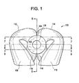
- FIG. 1 illustrates a front view of an exemplary embodiment of an exhaust diffuser (diffuser) 100.
- the diffuser 100 includes an annular inlet 102 having a planar area defined by an outer flow guide surface 104, an inner flow guide surface 106, a first collection chute 108 and a second collection chute 110, the collection chutes each having continuously increasing flow areas and are in fluid communication with the inlet 102 by radial turn portions 112 and 114 and right turn portions 116 and 118.
- FIG. 2 illustrates a rear view of the diffuser 100.
- FIG. 3 illustrates a side view of the diffuser 100 and an axis 301 of the inlet 102.
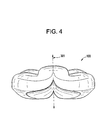
- FIG. 4 illustrates a top view of the diffuser 100.
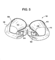
- FIG. 5 illustrates a bottom view of the diffuser 100 including a first collection chute outlet 508 and a second collection chute outlet 510 that are defined by the outer flow guide surface 104 and the inner flow guide surface 106.
- the first collection chute outlet 508 includes a diffusion portion 512 and a region 516 that are partially defined by a wedge shaped baffle portion 514.
- the second collection chute includes a diffusion portion 518 and a region 520; partially defined by a wedge shaped baffle portion 522.
- FIG. 6 illustrates a side cross-sectional view of the diffuser 100 along the line 6-6 (of FIG. 1 ).
- the inner flow guide surface 106 includes a hyperboloid shaped portion 602 concentric to the axis 301 of the inlet 102.
- the inlet 102 defines a planar area illustrated by the line 603. A positive region and a negative region are defined by the planar area illustrated by the line 603.
- the first collection chute outlet 508 and the second collection chute outlet 510 define coplanar areas illustrated by the line 605.
- the diffuser 100 receives a fluid such as, for example, exhaust steam discharged axially from a steam turbine (not shown) at the inlet 102.
- the fluid is guided by the inner flow surface 106 and outer flow surface 104 into flow paths.
- the inner flow surface 106 may include a hyperboloid shaped, elliptical, or conical shaped portion 602.
- a first flow path is indicated by the arrow 607.
- the first flow path 607 flows radially from the inlet to the first collection chute 108.
- the fluid in the first flow path 607 maintains a low diffusion rate in the radial turn portion 112 of the diffuser 100 from the inlet 102 to the first collection chute 108.
- the first collection chute 108 has a continuously increasing flow area that diffuses the fluid.
- the fluid exits the first collection chute outlet 508 and enters, for example, a condenser (not shown).
- a second flow path is indicated by the arrow 609, and flows from the inlet 102 to the outer flow guide surface 104 that directs the second flow path 609 in a 90 degree curve to exit the diffuser 100 from the region 516.
- the diffuser 100 is symmetrical in shape, thus the opposing half of the diffuser 100 (not shown in FIG. 6 ) defines a third flow path similar, to the first flow path 607, that flows through the radial turn portion 114 to the second collection chute 110 (of FIG. 1 ) and exits the second collection chute outlet 510 (of FIG. 5 ); and a fourth flow path 909 (of FIG. 9 ) similar, to the second flow path 609 that exits the region portion 520 (of FIG. 5 ).
- the diffuser 100 guides the fluid into fifth and sixth flow paths, described in further
- FIG. 7 illustrates a top cross-sectional view along the line 7-7 (of FIG. 1 ) including the first flow path 607 and the third flow path indicated by the arrow 707.
- FIG. 8 illustrates a top cross-sectional view along the line 8-8 (of FIG. 1 ).
- the illustrated embodiment includes a fifth flow path 801 and a similar sixth flow path 803.
- portions of the fluid entering the inlet 102 are guided into the flow paths 801 and 803, the flow paths 801 and 803 are directed by the inner flow guide surface 106 radially outward from the axis 301 and into the first and second collection chutes 108 and 110 where the fluid is diffused.
- the flow paths 801 and 803 exit the first and second collection chute outlets 512 and 518.
- FIG. 9 illustrates a top cross-sectional view along the line 9-9 (of FIG. 1 ).
- FIG. 9 further illustrates the second flow path 609 and the similar fourth flow path 909 (described above).
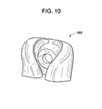
- FIGS. 10-12 illustrate perspective views of alternate exemplary embodiments of diffusers 1000, 1100, and 1200 that operate similarly to the diffuser 100 described above however, are shaped to occupy less area when installed in a system.
Landscapes
- Engineering & Computer Science (AREA)
- Mechanical Engineering (AREA)
- General Engineering & Computer Science (AREA)
- Jet Pumps And Other Pumps (AREA)
- Exhaust Silencers (AREA)
Applications Claiming Priority (1)
| Application Number | Priority Date | Filing Date | Title |
|---|---|---|---|
| US12/706,746 US8398359B2 (en) | 2010-02-17 | 2010-02-17 | Exhaust diffuser |
Publications (1)
| Publication Number | Publication Date |
|---|---|
| EP2357323A2 true EP2357323A2 (de) | 2011-08-17 |
Family
ID=43639937
Family Applications (1)
| Application Number | Title | Priority Date | Filing Date |
|---|---|---|---|
| EP11154543A Withdrawn EP2357323A2 (de) | 2010-02-17 | 2011-02-15 | Abgasdiffusor |
Country Status (4)
| Country | Link |
|---|---|
| US (1) | US8398359B2 (de) |
| EP (1) | EP2357323A2 (de) |
| JP (1) | JP2011169320A (de) |
| RU (1) | RU2011105279A (de) |
Cited By (8)
| Publication number | Priority date | Publication date | Assignee | Title |
|---|---|---|---|---|
| WO2014165161A1 (en) * | 2013-03-13 | 2014-10-09 | Roach John M Iii | Gas turbine engine exhaust fluid passage duct |
| FR3030633A1 (fr) * | 2014-12-22 | 2016-06-24 | Airbus Helicopters | Tuyere d'echappement d'un turbomoteur dont la sortie est perpendiculaire a l'axe de rotation du turbomoteur |
| RU2606298C1 (ru) * | 2015-08-31 | 2017-01-10 | Публичное акционерное общество Научно-производственное объединение "Искра" | Система выхлопа |
| RU2616433C1 (ru) * | 2016-04-06 | 2017-04-14 | Акционерное общество "Научно-производственная фирма "Невинтермаш" | Входное устройство центробежной турбомашины |
| RU2654556C2 (ru) * | 2016-02-11 | 2018-05-21 | Общество с ограниченной ответственностью "УралГазРемонт" | Способ снижения гидравлических потерь в выхлопном тракте газотурбинной установки и осерадиальный диффузор силовой турбины для его осуществления |
| RU182392U1 (ru) * | 2017-05-29 | 2018-08-15 | Акционерное общество "ЭКАТ" | Система выхлопа |
| CN109630219A (zh) * | 2018-12-16 | 2019-04-16 | 中国航发沈阳发动机研究所 | 一种燃气轮机排气装置 |
| RU2775619C1 (ru) * | 2021-03-23 | 2022-07-05 | Общество с ограниченной ответственностью "Газпром трансгаз Югорск" | Устройство отвода выхлопных газов газотурбинного двигателя |
Families Citing this family (8)
| Publication number | Priority date | Publication date | Assignee | Title |
|---|---|---|---|---|
| US9995160B2 (en) | 2014-12-22 | 2018-06-12 | General Electric Company | Airfoil profile-shaped seals and turbine components employing same |
| US10113484B2 (en) | 2015-12-21 | 2018-10-30 | General Electric Company | High pressure exhaust muffling device with multiple sources |
| DE102017124467A1 (de) * | 2017-10-19 | 2019-04-25 | Abb Turbo Systems Ag | Diffusoranordnung einer Abgasturbine |
| KR102874401B1 (ko) * | 2020-01-10 | 2025-10-22 | 한화에어로스페이스 주식회사 | 배기 덕트 및 이를 이용하는 배기 덕트 어셈블리와 비행체 |
| DE102021201115A1 (de) * | 2021-02-05 | 2022-08-11 | Rolls-Royce Solutions GmbH | Krümmer, Strömungsmaschine mit einem solchen Krümmer, Abgasturbolader mit einer solchen Strömungsmaschine, und Brennkraftmaschine mit einem solchen Krümmer |
| US11952962B1 (en) * | 2023-01-31 | 2024-04-09 | Pratt & Whitney Canada Corp. | Exhaust duct for gas turbine engine |
| CZ202383A3 (cs) * | 2023-03-02 | 2024-08-14 | Marek BobÄŤĂk | Deflektor turbíny |
| US12553450B2 (en) * | 2024-05-23 | 2026-02-17 | Pratt & Whitney Canada Corp. | Plenum closure panel with integrated airflow direction device |
Family Cites Families (14)
| Publication number | Priority date | Publication date | Assignee | Title |
|---|---|---|---|---|
| US1269998A (en) * | 1915-02-01 | 1918-06-18 | Westinghouse Electric & Mfg Co | Steam-turbine. |
| US3837760A (en) * | 1972-07-13 | 1974-09-24 | Stalker Corp | Turbine engine |
| US4212452A (en) * | 1979-04-30 | 1980-07-15 | Jack Hsieh | Apparatus for the direct reduction of iron ore |
| AT383396B (de) * | 1984-08-17 | 1987-06-25 | Proizv Ob Turbostroenia | Niederdruckzylinder einer dampfturbine |
| US5174120A (en) * | 1991-03-08 | 1992-12-29 | Westinghouse Electric Corp. | Turbine exhaust arrangement for improved efficiency |
| US5518366A (en) | 1994-06-13 | 1996-05-21 | Westinghouse Electric Corporation | Exhaust system for a turbomachine |
| US5494405A (en) | 1995-03-20 | 1996-02-27 | Westinghouse Electric Corporation | Method of modifying a steam turbine |
| JP3746614B2 (ja) * | 1998-07-28 | 2006-02-15 | 三菱重工業株式会社 | 低圧蒸気タービン排気室 |
| US6261055B1 (en) | 1999-08-03 | 2001-07-17 | Jerzy A. Owczarek | Exhaust flow diffuser for a steam turbine |
| US6419448B1 (en) * | 2000-03-20 | 2002-07-16 | Jerzy A. Owczarek | Flow by-pass system for use in steam turbine exhaust hoods |
| JP4541950B2 (ja) * | 2005-03-31 | 2010-09-08 | 株式会社日立製作所 | タービン排気装置及びその改造方法 |
| GB2440343B (en) * | 2006-07-25 | 2008-08-13 | Siemens Ag | A gas turbine arrangement |
| EP1921278A1 (de) * | 2006-11-13 | 2008-05-14 | ALSTOM Technology Ltd | Diffusor-und Abdampfsystem für Turbine |
| US8317467B2 (en) * | 2009-12-29 | 2012-11-27 | General Electric Company | Radial channel diffuser for steam turbine exhaust hood |
-
2010
- 2010-02-17 US US12/706,746 patent/US8398359B2/en not_active Expired - Fee Related
-
2011
- 2011-02-15 JP JP2011029254A patent/JP2011169320A/ja not_active Withdrawn
- 2011-02-15 EP EP11154543A patent/EP2357323A2/de not_active Withdrawn
- 2011-02-15 RU RU2011105279/06A patent/RU2011105279A/ru not_active Application Discontinuation
Non-Patent Citations (1)
| Title |
|---|
| None |
Cited By (11)
| Publication number | Priority date | Publication date | Assignee | Title |
|---|---|---|---|---|
| WO2014165161A1 (en) * | 2013-03-13 | 2014-10-09 | Roach John M Iii | Gas turbine engine exhaust fluid passage duct |
| US9909459B2 (en) | 2013-03-13 | 2018-03-06 | Rolls-Royce Corporation | Gas turbine engine exhaust fluid passage duct |
| FR3030633A1 (fr) * | 2014-12-22 | 2016-06-24 | Airbus Helicopters | Tuyere d'echappement d'un turbomoteur dont la sortie est perpendiculaire a l'axe de rotation du turbomoteur |
| RU2606298C1 (ru) * | 2015-08-31 | 2017-01-10 | Публичное акционерное общество Научно-производственное объединение "Искра" | Система выхлопа |
| RU2654556C2 (ru) * | 2016-02-11 | 2018-05-21 | Общество с ограниченной ответственностью "УралГазРемонт" | Способ снижения гидравлических потерь в выхлопном тракте газотурбинной установки и осерадиальный диффузор силовой турбины для его осуществления |
| RU2616433C1 (ru) * | 2016-04-06 | 2017-04-14 | Акционерное общество "Научно-производственная фирма "Невинтермаш" | Входное устройство центробежной турбомашины |
| RU182392U1 (ru) * | 2017-05-29 | 2018-08-15 | Акционерное общество "ЭКАТ" | Система выхлопа |
| CN109630219A (zh) * | 2018-12-16 | 2019-04-16 | 中国航发沈阳发动机研究所 | 一种燃气轮机排气装置 |
| CN109630219B (zh) * | 2018-12-16 | 2022-03-04 | 中国航发沈阳发动机研究所 | 一种燃气轮机排气装置 |
| RU2775619C1 (ru) * | 2021-03-23 | 2022-07-05 | Общество с ограниченной ответственностью "Газпром трансгаз Югорск" | Устройство отвода выхлопных газов газотурбинного двигателя |
| RU2823757C1 (ru) * | 2023-09-27 | 2024-07-29 | Общество с ограниченной ответственностью "Газпром трансгаз Казань" | Способ снижения аэродинамического сопротивления отработанных выхлопных газов в выхлопном тракте газоперекачивающего агрегата |
Also Published As
| Publication number | Publication date |
|---|---|
| US8398359B2 (en) | 2013-03-19 |
| JP2011169320A (ja) | 2011-09-01 |
| RU2011105279A (ru) | 2012-08-20 |
| US20110200421A1 (en) | 2011-08-18 |
Similar Documents
| Publication | Publication Date | Title |
|---|---|---|
| EP2357323A2 (de) | Abgasdiffusor | |
| US8235648B2 (en) | Diffuser with enhanced surge margin | |
| EP2385219A2 (de) | Diffusor einer Gasturbine zwischen Verdichteraustritt und Brennkammereintritt | |
| US6279322B1 (en) | Deswirler system for centrifugal compressor | |
| RU2441987C2 (ru) | Газотурбинная система | |
| US11215196B2 (en) | Diffuser pipe with splitter vane | |
| US4375938A (en) | Roto-dynamic pump with a diffusion back flow recirculator | |
| EP2341215A2 (de) | Hohler Dampfleitungsverteiler mit verbesserter Druckwiedergewinnung | |
| US8287236B2 (en) | Multistage centrifugal compressor | |
| EP1788310A3 (de) | Gasturbinensystem zur Kopplung der Luftströmung aus dem Radialverdichter mit der Axialbrennkammer | |
| EP2341220A2 (de) | Radialer Kanaldiffusor für eine Dampfturbinen-Abdampfhaube | |
| CN112334665B (zh) | 用于制冷系统的混流式压缩机构造 | |
| US8075260B2 (en) | Centrifugal turbomachinery | |
| KR20010042504A (ko) | 증기 터빈 | |
| CN102052090B (zh) | 轴流式涡轮机以及用于从轴流式涡轮机中排出流的方法 | |
| JPH1122695A (ja) | 遠心圧縮機のインペラ翼構造 | |
| CN109681471B (zh) | 一种用于多级离心压缩机的间隔组件 | |
| US11378005B1 (en) | Compressor diffuser and diffuser pipes therefor | |
| JP2011117402A (ja) | 遠心流体機械の吸込ケーシング | |
| CN220522838U (zh) | 离心风机 | |
| CN220522888U (zh) | 离心风机 | |
| JP2006200489A (ja) | 遠心形流体機械およびその吸込ケーシング | |
| CN209818396U (zh) | 一种用于多级离心压缩机的间隔组件 | |
| CN119236541A (zh) | 一种高分离效率低流阻损耗离心通风器结构 | |
| JP2003074308A (ja) | ガスタービン |
Legal Events
| Date | Code | Title | Description |
|---|---|---|---|
| PUAI | Public reference made under article 153(3) epc to a published international application that has entered the european phase |
Free format text: ORIGINAL CODE: 0009012 |
|
| AK | Designated contracting states |
Kind code of ref document: A2 Designated state(s): AL AT BE BG CH CY CZ DE DK EE ES FI FR GB GR HR HU IE IS IT LI LT LU LV MC MK MT NL NO PL PT RO RS SE SI SK SM TR |
|
| AX | Request for extension of the european patent |
Extension state: BA ME |
|
| STAA | Information on the status of an ep patent application or granted ep patent |
Free format text: STATUS: THE APPLICATION IS DEEMED TO BE WITHDRAWN |
|
| 18D | Application deemed to be withdrawn |
Effective date: 20150901 |