EP2357839A2 - Verfahren und Vorrichtung zur Verarbeitung dreidimensionaler Bilder - Google Patents
Verfahren und Vorrichtung zur Verarbeitung dreidimensionaler Bilder Download PDFInfo
- Publication number
- EP2357839A2 EP2357839A2 EP11161315A EP11161315A EP2357839A2 EP 2357839 A2 EP2357839 A2 EP 2357839A2 EP 11161315 A EP11161315 A EP 11161315A EP 11161315 A EP11161315 A EP 11161315A EP 2357839 A2 EP2357839 A2 EP 2357839A2
- Authority
- EP
- European Patent Office
- Prior art keywords
- parallax
- images
- dimensional
- camera
- display
- Prior art date
- Legal status (The legal status is an assumption and is not a legal conclusion. Google has not performed a legal analysis and makes no representation as to the accuracy of the status listed.)
- Withdrawn
Links
Images

















Classifications
-
- H—ELECTRICITY
- H04—ELECTRIC COMMUNICATION TECHNIQUE
- H04N—PICTORIAL COMMUNICATION, e.g. TELEVISION
- H04N13/00—Stereoscopic video systems; Multi-view video systems; Details thereof
- H04N13/10—Processing, recording or transmission of stereoscopic or multi-view image signals
- H04N13/106—Processing image signals
- H04N13/128—Adjusting depth or disparity
-
- H—ELECTRICITY
- H04—ELECTRIC COMMUNICATION TECHNIQUE
- H04N—PICTORIAL COMMUNICATION, e.g. TELEVISION
- H04N13/00—Stereoscopic video systems; Multi-view video systems; Details thereof
-
- H—ELECTRICITY
- H04—ELECTRIC COMMUNICATION TECHNIQUE
- H04N—PICTORIAL COMMUNICATION, e.g. TELEVISION
- H04N13/00—Stereoscopic video systems; Multi-view video systems; Details thereof
- H04N13/20—Image signal generators
- H04N13/204—Image signal generators using stereoscopic image cameras
- H04N13/239—Image signal generators using stereoscopic image cameras using two two-dimensional [2D] image sensors having a relative position equal to or related to the interocular distance
-
- H—ELECTRICITY
- H04—ELECTRIC COMMUNICATION TECHNIQUE
- H04N—PICTORIAL COMMUNICATION, e.g. TELEVISION
- H04N13/00—Stereoscopic video systems; Multi-view video systems; Details thereof
- H04N13/10—Processing, recording or transmission of stereoscopic or multi-view image signals
- H04N13/106—Processing image signals
- H04N13/122—Improving the three-dimensional [3D] impression of stereoscopic images by modifying image signal contents, e.g. by filtering or adding monoscopic depth cues
Definitions
- 3D display three-dimensional image display
- 3D display has been studied in various manners and has found practical applications in somewhat limited markets, which include uses in the theater or ones with the help of special display devices. From now on, it is expected that the research and development in this area may further accelerate toward the offering of contents full of sense of reality and the times may come when individual users enjoy 3D display at home.
- 3D display is something expected to gain its popularity in the years ahead, and for that reason too, forms of display that could not be imagined from the current display devices are being proposed.
- a technology has been disclosed whereby a selected partial image of a two-dimensional image is displayed three-dimensionally (See, for example, Japanese Patent Application Laid-Open No. Hei011-39507 ).
- too much parallax can cause problems; in fact, certain viewers of 3D images (hereinafter referred to also as "user") may sometimes complain of a slight uncomfortable feeling. This, of course, is caused by a variety of factors, which may include not only the 3D display itself but also a disagreement between the scene being displayed and the user's surrounding circumstances or his/her sense. However, according to our rule of thumb, such a problem tends to occur due to a too large parallax; in other words, it is likely to be observed when the stereoscopic effect is too strong.
- the general programmers can realize, by calling this library, the appropriate 3D display without being conscious of complicated principles of stereovision or programming.
- the present invention relates to a three-dimensional image processing apparatus, and it includes: an instruction acquiring unit which acquires a response of a user to a three-dimensional image displayed on the basis of a plurality of viewpoint images corresponding to different parallaxes; and a parallax specifying unit which specifies an appropriate parallax on the user based on the acquired response.
- the "parallax” is a parameter to produce a stereoscopic effect and various definitions therefor are possible. As an example, it can be represented by a shift amount of pixels that represent the same position among the viewpoint images. Hereinafter, the present specification follows this definition unless otherwise stated.
- optical axis intersecting surface means a state where there is given a parallax in a manner such that stereovision is done in front of a surface (hereinafter referred to as “optical axis intersecting surface” also) at camera's line of sight placed at the respective plurality of viewpoints, namely, intersecting positions of an optical axis (hereinafter referred to as “optical axis intersecting positions” also).
- optical axis intersecting positions also.
- being “farther-positioned” means a state where there is given a parallax in a manner such that stereovision is done behind the optical axis intersecting surface.
- the parallax control unit may determine shift amounts of the plurality of two-dimensional images in a horizontal direction according to the appropriate parallax.
- the input for 3D display is not produced, with a high degree of freedom, from three-dimensional data but is the parallax image to which parallax has already been given, so that the parallax is fixed.
- redrawing or rephotographing processing by changing a camera position and going back to the original three-dimensional space or actually-shot real space cannot be done.
- the parallax is adjusted by horizontally shifting viewpoints that constitute a parallax image or pixels contained in them.
- each of these steps is implemented as a library function for three-dimensional display and configuration is such that the library function can be called up as a function from a plurality of programs, it will not be necessary for a program to describe the program each time in consideration of hardware of a three-dimensional display apparatus, thus being effective.
- Another embodiment of the present invention relates also to a three-dimensional image processing apparatus, and it includes: a parallax amount detecting unit which detects a first parallax amount caused when displaying a three-dimensional image from a plurality of viewpoint images; and a parallax control unit which varies parallax amounts of the plurality of viewpoint images so that the first parallax amount falls within a range of a second parallax amount which is a user's permissible parallax amount.
- This is a typical example of "automatic adjustment”, and the above-described appropriate parallax can be used as the second parallax amount.
- An example of this processing is shown in FIG. 46 which will be described later.
- the parallax amount detecting unit may detect the first parallax amount by computing matching of corresponding points among the plurality of viewpoint images or may detect the first parallax amount recorded beforehand in any header of the plurality of viewpoint images. An example for these processings is shown in FIG. 47 which will be described later.
- the parallax control unit may vary parallax amounts among the plurality of viewpoint images by shifting synthesis positions of the plurality of viewpoint images. These are common to FIG. 45 to FIG. 47 .
- the shifting of synthesis positions is the shifting in the horizontal or vertical direction in units of pixels or the whole image. If the input is images with depth information, the parallax control unit may vary the parallax amount by adjusting the depth information.
- Still another embodiment of the present invention relates also to a method for processing three-dimensional images, and it includes the steps of: detecting a first parallax amount caused when displaying a three-dimensional image from a plurality of viewpoint images; and varying parallax amounts of the plurality of viewpoint images so that the first parallax amount falls within a range of a second parallax amount which is a user's permissible parallax amount.
- the third group is based on a technique in which parallax is corrected based on the position in an image.
- This "automatic correction" operates to alleviate user's sense of discomfort or rejection against 3D display and can be used in combination with the first group and the second group technique.
- the technical or physiological problems such as those in which, at the time of three-dimensional display, as it is closer to edge of an image, a plurality of viewpoint images are likely to be observed as being dislocated or a sense of discomfort is likely to be caused.
- the third group tries to alleviate this problem by a processing with which parallax is reduced at part near the edge of an image or the parallax is adjusted so that an object moves from nearer-position side to farther-position side. The following relates to the third group.
- the parallax control unit diminishes a parallax at the periphery of, for example, the plurality of viewpoint images or changes the parallax so that an object is perceived farther from a user.
- the parallax control unit may vary the parallax by selectively performing a processing on any of the plurality of viewpoints images.
- the parallax control unit may generate the parallax images while obeying the limit parallax by controlling the camera parameters based on the three-dimensional data, may generate the parallax images by controlling the depth of images having depth information attached thereto, or may generate the parallax images after the shift amount of a plurality of two-dimensional images having parallax in the horizontal direction has been decided.
- the fifth group of the present invention relates to an application or business model using the above-described three-dimensional processing technologies or their related technologies.
- a software library for the fourth group can be utilized. The following relates to the fifth group.
- It may further include: reading information on the first display apparatus into the second display apparatus; and correcting, by the second display apparatus according to the appropriate parallax, parallax of the parallax images whose parallax has been adjusted by the step of adjusting parallax of parallax images, based on the read-in information on hardware of the first display apparatus and information on hardware of the second display apparatus.
- It may further include: an object specifying unit which receives, from a user, specification of a predetermined object contained in the three-dimensional image; and an optical axis intersecting position setting unit which associates intersecting positions of optical axes associated with the respective plurality of viewpoint images with specified object positions and which sets the intersecting positions of optical axes so that the specified object is expressed in the vicinity of a position of a display screen on which the three-dimensional image is displayed.
- the specified object may have a predetermined boundary face and the optical axis intersecting position setting unit may associate the intersecting position of optical axis on the boundary face.
- the three-dimensional image may be generated from three-dimensional data. If the three-dimensional image is generated from the three-dimensional data, it is easy to add various effects to the three-dimensional image. For example, when expressing an object in such a manner as to go over a boundary face, namely, a display screen, such an effect as to deform the display screen can be added.
- Still another embodiment of the present invention relates to a method for processing three-dimensional images.
- This method for processing three-dimensional images includes the step of changing moving velocity of an object which is contained in a three-dimensional image generated based on a plurality of viewpoint images corresponding to different parallaxes and which is to be expressed in a basic representation space that contains an object to be three-dimensionally displayed, in nearer-position or farther-position direction.
- Still another embodiment of the present invention relates also to a method for processing three-dimensional images.
- This method for processing three-dimensional images is such that when parallax of an object to be expressed within a basic representation space that contains an object to be three-dimensionally displayed is calculated in the event that a three-dimensional image is generated based on a plurality of viewpoint images corresponding to different parallaxes, the parallax of an object is calculated as size that contains an extended area to the rear of the object in place of actual size of the object.
- the object may be expressed in such a manner as to move the extended area in back thereof.
- This three-dimensional image processing apparatus includes a parallax control unit which controls a ratio of the width to the depth of an object expressed within a three-dimensional image when the three-dimensional image is generated from a two-dimensional image to which depth information is given so that a parallax formed thereby does not exceed a parallax properly perceived by human eyes.
- Still another embodiment of the present invention relates also to a three-dimensional image processing apparatus.
- This three-dimensional image processing apparatus is such that if a parameter on camera placement set for generating viewpoint images is to be changed in the event of generating three-dimensional images from data, the camera parameter falls within threshold values which are provided beforehand for a variation of the parameter. According to this, a sense of discomfort felt by a viewer of a three-dimensional image due to a rapid change in parallax can be reduced.
- Still another embodiment of the present invention relates also to a three-dimensional image processing apparatus.
- This three-dimensional image processing apparatus is such that in a case when moving images of three-dimensional images are generated from two-dimensional moving images to which depth information are given, control is performed so that a variation, caused by progression of the two-dimensional moving images, in a maximum value or minimum value of depth contained in the depth information falls within threshold values provided beforehand. According to this apparatus, a sense of discomfort felt by a viewer of a three-dimensional image due to a rapid change in parallax can be reduced.
- FIGS. 3 and 4 show, respectively, the states of A times (A ⁇ 1) and B times (B>1) the positional relationship of FIG. 2 .
- the parallax images obtained in these positional relationships can also realize the ideal state of FIG. 1 . That is, the basics of ideal 3D display begins with ensuring a constant of W:D:E. This relationship serves also as a basis for producing parallax.
- the second three-dimensional image processing apparatus 100 proves effective for parallax adjustment of a plurality of two-dimensional images with parallax already given, namely, existing parallax images, so that two-dimensional parallax images are inputted thereto.
- the third three-dimensional image processing apparatus 100 realizes appropriate parallax by operating the depth information of images with depth information, so that the main input thereto is images with depth information.
- information acquired by the information acquiring unit 118 there are the number of viewpoints for 3D display, the system of a stereo display apparatus such as space division or time division, whether shutter glasses are used or not, the arrangement of viewpoint images in the case of a multiple-eye system, whether there is any arrangement of viewpoint images with inverted parallax among the parallax images, the result of head tracking and so forth. Exceptionally, however, the result of head tracking is inputted directly to a camera placement determining unit 132 via a route not shown and processed there.
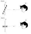
- FIG. 15 shows schematically a sense of distance perceived by a user 10 has when these five black circles are displayed.
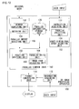
- the user 10 is responding with "appropriate” for the range of the sense of distance for these five, and this response is acquired by an instruction acquiring unit 122.
- the five black circles with different parallaxes are displayed all at once or one by one, and the user 10 performs inputs indicating whether the parallax is permissible or not.
- the display itself is done in a single black circle, whose parallax is changed continuously, and the user 10 responds when the parallax reaches a permissible limit in each of the farther and the nearer placement direction.
- the response may be made using any known technology, which includes ordinary key operation, mouse operation, voice input and so forth.
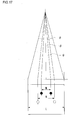
- E is the distance between viewpoints.
- point G which is a pixel without parallax given, is positioned where the optical axes K2 from the both cameras intersect with each other on the optical axis intersection plane 210, and the optical axis intersection plane 210 is positioned at a screen surface.
- the beams of light K1 that produce the nearer-positioned maximum parallax P intersect on the front projection plane 30, and the beams of light K3 that produce the farther-positioned maximum parallax Q intersect on the back projection plane 32.
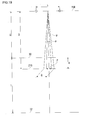
- FIG. 20 shows a four-eye camera arrangement by four cameras 22, 24, 26 and 28.
- the above-mentioned A and E should be determined to achieve an appropriate parallax between adjacent cameras, such as between the first camera 22 and the second camera 24.
- nearly the same effect is obtained by using the A and E determined between the second camera 24 and the third camera 26, which are closer to the center, as those between the other cameras as well.
- T may be determined for the coordinates of the nearest-positioned object and the farthest-positioned object in the three-dimensional space, and if this is done in real time, the objects can, without fail, be positioned in the basic representation space T.
- a short-time exception can be made by applying a relaxing condition that "the average position of objects in a certain period of time stays within the basic representation space T".
- the objects that define the basic representation space T may be limited to stationary objects, and in this case, dynamic objects can be given such exceptional behavior as sticking out from the basic representation space T.
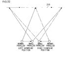
- FIG. 23 shows another example in which the camera placement determining unit 132 changes parallax by changing the placement of cameras according to the instructions from the distortion processing unit 136.
- the left-hand camera only of the two cameras is moved, and as it is moved toward the periphery of the image, the parallax changes from "normal parallax" to "intermediate parallax” to "smaller parallax". This method involves lower computation cost than the one in FIG. 22 .
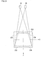
- FIG. 24 shows another example of a correction map. This map also changes the parallaxes; the normal parallax is left untouched near the center of the image and the parallax in other parallax correction areas is made smaller gradually.
- FIG. 25 shows camera placement which the camera placement determining unit 132 changes according to the map. Only when the camera direction has deflected widely from the front, "small parallax" is given with the position of the left camera moving closer to the right camera.
- the space is squeezed more in the depth direction as indicated by the arrows, in positions closer to the periphery, and a sense of distance not too different from a constant sense of distance as indicated by point W in the same Figure is given whether in a nearer position or a farther position.
- a sense of distance not too different from a constant sense of distance as indicated by point W in the same Figure is given whether in a nearer position or a farther position.
- FIG. 36 is for a verification of this conversion.
- considered is the region where X ⁇ 0 and Z ⁇ 0.
- point (X0, Y0, Z0) moves to point (X1, Y1, Z1) as a result of reduction processing
- the reduction rates Sx, Sy and Sz are:
- FIG. 40 shows a principle of another distortion conversion for a depth map. Since the space, more strictly speaking, is radially observed from the user 10, the reduction processings in the X-axis and Y-axis directions are also combined. Here, the center of the eyes is used as the viewing position. The specific processings are done with the same formulas as in FIG. 36 . Although the original depth map has Z values only, the X values and Y values are also stored when this calculation is done. The Z values are converted into pixel shift amounts in the X direction or the Y direction, and the X values and the Y values may be stored as offset values in relation to them.
- FIG. 42 shows a shift processing at the pixel level.
- a first quadrilateral 250 and a second quadrilateral 252 are both caught in a left-eye image 200 and a right-eye image 202.
- the first quadrilateral 250 is given a nearer-positioned parallax, whose parallax amount is expressed by a positive number as "6 pixels".
- the second quadrilateral 252 is given a farther-positioned parallax, whose parallax amount is expressed by a negative number as "-6 pixels”.
- these parallax amounts are denoted by F2 and F1, respectively.
- FIG. 46 is a flow showing an automatic adjustment by a second three-dimensional image processing apparatus 100.
- the generation of right and left images (S30) and the distribution of the images (S32), which are the procedure 270 of the image creator, are the same as in FIG. 45 .
- the reception of the images (S34) in the procedure 272 of the second three-dimensional image processing apparatus 100 is not different.
- parallaxes given in advance among parallax images, especially the maximum parallaxes are detected by a matching unit 158 of a parallax amount detecting unit 150 (S36), and, on the other hand, appropriate parallaxes, especially the limit parallaxes, are acquired from a parallax information storage unit 120 (S38).
- a position shifting unit 160 shifts the synthesis position of the images so as to satisfy the limit parallaxes by the aforementioned processing (S40), and the image is three-dimensionally displayed after the processings by a parallax write unit 164, an image edge adjusting unit 168 and a format conversion unit 116 (S42).
- FIG. 47 is a flow showing still another automatic adjustment by a second three-dimensional image processing apparatus 100.
- the maximum parallax at this point is detected (S52) and recorded in the header of a viewpoint image of any of the parallax images (S54). This detection may be accomplished by a corresponding-point matching, but when parallax images are created manually by a creator, the maximum parallax is naturally known in the editing process, and therefore it may be recorded. Then the image is distributed (S56).
- the receipt of images (S58) in the procedure 272 of the second three-dimensional image processing apparatus 100 is the same as in FIG. 46 .
- the above-mentioned maximum parallax is read out from the header by a header inspecting unit 156 of a parallax amount detecting unit 150 (S60).
- the limit parallaxes are acquired from a parallax information storage unit 120 (S62), and the subsequent processings S64 and S66 are the same as the processings S40 and S42 in FIG. 46 , respectively. According to this method, it is not necessary to calculate the maximum parallax. Also, it is possible to realize an appropriate three-dimensional sense for the whole image.
- header information in at least one of the multiple viewpoint images, but when the multiple viewpoint images are synthesized in a single image, the header of the image can be utilized.
- FIGS. 48 through 51 show processings for shifting the synthesis position for images with depth information. These are done by a two-dimensional image generating unit 178 of a third three-dimensional image processing apparatus 100.
- FIG. 48 and FIG. 49 each show a plane image 204 and depth map constituting an image with depth information. Here, nearer-position depths are denoted by plus, and farther-position depths by minus.
- the first quadrilateral 250 is at the nearest-position point, the second quadrilateral 252 at an intermediate nearer-position point and the third quadrilateral 254 at the farthest-position point.
- the two-dimensional image generating unit 178 Based on the original plane image 204, the two-dimensional image generating unit 178 generates an other viewpoint image by first performing a processing of shifting the pixels by values of the depth map. If reference is to be the left-eye image, the original plane image 204 will be the left-eye image as it is. As shown in FIG. 50 , a right-eye image 202 is produced by shifting the first quadrilateral 250 four pixels to the left, the second quadrilateral 252 two pixels to the left and the third quadrilateral 254 four pixels to the right. An image edge adjusting unit 168 fills up a lost part 260, of pixel information, caused by the movement of the objects by the adjacent pixels, which have a parallax of "0" and are considered to be the background.
- the depth map of FIG. 49 will be converted to the depth map of FIG. 51 by this conversion formula. That is, "4" is converted to "2", “2" to "1” and “-4" to "-3", respectively.
- the intermediate value between K1 and K2 are converted into the value between J1 and J2.
- Fxy is not an integer, a rounding off or a processing to make the nearer-position parallax smaller may be carried out.
- the three-dimensional processing apparatus 100 has been described as an apparatus, this may be a combination of hardware and software and it can be structured by software alone. In such a case, convenience will increase if an arbitrary part of the three-dimensional image processing apparatus 100 is turned into a library so that calling can be made from various programs. A programmer can skip the part of programming which requires knowledge of 3D display. For users, trouble of re-setting will be saved because the operation concerning 3D display, namely, the GUI is of the same kind irrespective of software or contents and thus the information set may be shared by the other software.
- information instead of processings for 3D display, can be shared among a plurality of programs.
- Various programs can determine the status of image by referring to such information.
- An example of information that can be shared is information acquired by the information acquiring unit 118 of the above-described three-dimensional image processing apparatus 100. This information may be stored in a recording unit (not shown) or a correction map storage unit 140 or the like.
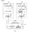
- FIGS. 52 to 54 show an example in which an above-described three-dimensional image processing apparatus 100 is used as a library.
- FIG. 52 shows a usage of a three-dimensional display library 300.
- the three-dimensional display library 300 is referred to in the form of calling out functions from a plurality of programs, such as program A 302, program B 304 and program C 306. Stored in a parameter file 318 are not only the above-described information but also the user's appropriate parallaxes and so forth.
- the three-dimensional display library 300 is used by a plurality of apparatuses, such as apparatus A 312, apparatus B 314 and apparatus C 316, via API (Application Program Interface) 310.
- API Application Program Interface
- program A 302 and others are games, three-dimensional applications which are so-called Web3Ds, three-dimensional desktop screens, three-dimensional maps, viewers of parallax images which are two-dimensional images, and viewers of images with depth information and so forth. Some games may naturally differ in the usage of coordinates, but the three-dimensional display library 300 can cope with that.
- examples of apparatus A 312 and others are arbitrary three-dimensional display apparatuses using parallax, which may include the two- or multiple-eye parallax barrier type, the shutter glasses type and the polarizing glasses type.
- FIG. 53 shows an example in which a three-dimensional display library 300 is incorporated into three-dimensional data software 402.
- the three-dimensional data software 402 is comprised of a program body 404, a three-dimensional display library 300 to realize appropriate parallaxes therefor, and a shooting instruction processing unit 406.
- the program body 404 communicates with the user via a user interface 410.
- the shooting instruction processing unit 406 performs a virtual camera shooting of a predetermined scene during the operation of the program body 404 according to instructions from the user.
- the shot image is recorded in an image recording apparatus 412. It is also outputted to a three-dimensional display apparatus 408.
- the three-dimensional image processing apparatus 100 and the three-dimensional display library 300 can remove such adverse effect and contribute to the enhancement of 3D display applications.
- a first three-dimensional image processing apparatus 100 is capable of high-accuracy processing with the input of three-dimensional data.
- the three-dimensional data may be once brought down to images with depth information, and parallax images therefor may be generated using a third three-dimensional image processing apparatus 100.
- such a processing may result in lower calculation cost.
- FIG. 55 shows a state in which an image structured by three-dimensional data is displayed on a display screen 400.
- one glass surface 401 of a tank 410 coincides with the display screen 400, and that a fish 301 is swimming in the fish tank 410 is being expressed.
- the fish 301 is normally expressed as if it is swimming in the farther-position space as shown in FIG. 56 , and every now and then, as shown in FIG. 57 , the expression can be made such that "the fish 301 appears in the nearer-position space after breaking through the display screen 400".
- FIG. 60 shows a structure of a fourth three-dimensional image processing apparatus 100 to realize the above-described processing.
- This three-dimensional image processing apparatus 100 is of a structure with an object specifying unit 180 added to the three-dimensional sense adjusting unit 112 of the first three-dimensional image processing apparatus 100 shown in FIG. 11 .
- This object specifying unit 180 performs a processing to position the boundary face of an object specified by the user near or exactly at the display screen.
- the user is assumed to be a producer of three-dimensional images, and the above-mentioned processing is done at the time of producing or editing three-dimensional images. It is to be noted that the user may be a viewer, too.
- FIG. 61 shows, for convenience, an illustration in the depth direction, especially a basic representation space T, concerning an image displayed on a fourth three-dimensional image processing apparatus 100.
- a front projection plane 310 is set on the left of this Figure and a back projection plane 312 on the right thereof, and the space between the front projection plane 310 and the back projection plane 312 is the basic representation space T.
- a region without the presence of any object is included in the basic representation space T.
- a region without the presence of any object is provided, as part of the basic representation space T, in the further front of the house 350, which is a still object in front, and thus the bird 330, which is a dynamic object, may be able to move in front of the house 350.
- a region without the presence of any object is also further provided, as part of the basic representation space T, in the further back of the tree 370, which is a stationary object placed in back.
- a moving object 390 as an object for parallax calculation, is formed, for instance, in such a manner that not only the bird 330 itself but also the spaces in front and back are included therein.
- the forefront surface of the moving object 390 reaches the front projection plane 310, the bird 330 only is moved. In that case, by slowing the moving velocity of the bird 330 from the original speed, the timing can be delayed for the bird 330 to reach the front projection plane 310 too quickly to make the expressing thereafter impossible.
- the bird 330 may be so arranged, for instance, that after the moving object 390 has gone past the front projection plane 310, the bird 330 is allowed to move in a previously included space.
- the maximum parallax is determined by the moving object 390, and the bird 330, which nears the maximum parallax gradually, can keep moving forward in real space. This can be realized by a judgment to enable or disable the movement depending on the position of the object, or the bird 330.
- the moving velocity may be set to any of the originally assumed moving velocity, a fast velocity or a slow velocity; the flexibility given to the moving velocity makes a variety of expressions possible. For example, by changing the moving velocity slower in positions closer to the end of the moving object 390, the movement forward can be expressed while preventing excessively large parallax amount in the forward and the backward direction.
- the maximum parallax will now depend on the object. Hence, the bird 330 is returned gradually to the original position within the moving object 390.
- M ⁇ LEA ⁇ / 2 ⁇ S ⁇ A ⁇ + S ⁇ tan & thetas ; / 2 M ⁇ M ⁇
- M ⁇ LE ⁇ A ⁇ / 2 ⁇ S ⁇ ⁇ A ⁇ + S ⁇ tan & thetas ; / 2
- M ⁇ M" ⁇ M' rapid changes in parallax amount can be prevented when an object moving toward the viewer is displayed three-dimensionally.
- This three-dimensional image display apparatus 100 can be realized by a three-dimensional image display apparatus 100 shown in FIG. 60 .
- a camera placement determining unit 132 is further provided with a function of reading, from original data, information on the range on which the calculation is to be done in a basic representation space or information on the change of parallax amount for an object, when correcting the temporarily set camera parameters according to the appropriate parallax, and reflecting them on camera parameters.
- the information may be incorporated into the original data themselves or may, for instance, be stored in a parallax information storage unit 120.
- the processing is such that the parallax of a three-dimensional image is made smaller when an appropriate parallax processing judges that the parallax is in a state of being too large for a correct parallax condition where a sphere can be seen correctly.
- the sphere is seen in a form crushed in the depth direction, but a sense of discomfort for this kind of display is generally small. People, who are normally familiar with plane images, tend not to have a sense of discomfort, most of the time, as long as the parallax is between 0 and a correct parallax state.
- the processing will be such that the parallax is made larger when an appropriate parallax processing judges that the parallax of a three-dimensional image is too small for a parallax condition where a sphere can be seen correctly.
- the sphere is, for instance, seen in a form swelling in the depth direction, and people may have a sense of significant discomfort for this kind of display.
- parallax correction can be made using the above-described first to fourth three-dimensional image processing apparatuses 100. Assumed here is the generation of three-dimensional images from three-dimensional data by a first three-dimensional image processing apparatuses 100 shown in FIG. 11 . It is to be noted that the above-mentioned correction processing can be realized by the fourth and the sixth three-dimensional image processing apparatus 100 to be described later.
- FIG. 66 shows a state in which a viewer is viewing a three-dimensional image on a display screen 400 of a three-dimensional image display apparatus 100.
- the screen size of the display screen 400 is L
- the distance between the display screen 400 and the viewer is d
- the distance between eyes is e.
- the nearer-position limit parallax M and the farther-position limit parallax N have already been obtained beforehand by a three-dimensional sense adjusting unit 112, and appropriate parallaxes are between the nearer-position limit parallax M and the farther-position limit parallax N.
- the nearer-position limit parallax M only is displayed, and the maximum fly-out amount m is determined from this value.
- a camera placement is determined as shown in FIG. 67 by a camera placement determining unit 132 of a parallax control unit 114, with reference to the nearest-position point and the farthest-position point of the sphere 21.
- the optical axis intersection distance of the two cameras 22 and 24 is D, and the interval between the cameras is Ec.
- an enlargement/reduction processing of the coordinate system is done in a manner such that the subtended width of the cameras at the optical axis intersection distance coincides with the screen size L.
- the sphere 21 looks correctly when the viewer view it from the camera position shown in FIG. 67 . If an image generated by a shooting system like this is viewed as a sphere 21 on the original three-dimensional image display apparatus 100, a sphere 21 elongated in the depth direction for the whole appropriate parallax range is viewed as shown in FIG. 69 .
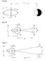
- FIG. 70 shows a state in which the nearest-position point of a sphere positioned at a distance of A from the display screen 400 is shot from a camera placement shown in FIG. 67 .
- the maximum parallax M corresponding to distance A is determined by the two straight lines connecting each of the two cameras 22 and 24 with the point positioned at distance A.
- FIG. 71 shows the camera interval E1 necessary for obtaining the parallax M shown in FIG. 70 when an optical axis tolerance distance of the cameras from the two cameras 22 and 24 is d.
- Ec e ⁇ D + T - A / d + T - A
- the camera interval Ec is preferably set in such a manner as to satisfy the following two equations simumultaneously: Ec ⁇ e ⁇ D - A / d - A Ec ⁇ e ⁇ D + T - A / d + T - A
- the interval of two cameras placed on the two optical axes K4 connecting the two cameras 22 and 24 placed at the position of viewing distance d at an interval of the distance e between eyes with the nearest-position point of an object or on the two optical axes K5 connecting the above-mentioned two cameras 22 and 24 with the farthest-position point thereof is the upper limit of the camera interval Ec.
- the depth map values denote the dislocation amounts at the points in the number of pixels and the initial values, or generally the values described in the original data, are in a state realizing an optimum stereoscopic vision, then it is preferably that the above-mentioned processing will not be performed when there occurs a necessity for enlarging the range of depth map values by an appropriate parallax processing, and the above-mentioned processing is performed only when there occurs a necessity for reducing the range of depth map values, that is, when there occurs a necessity for making the parallax smaller.
- the maximum permissible value may be stored in a header area of the image or the like and an appropriate parallax processing may be performed such that the parallax is set below the maximum permissible value.
- hardware information is necessary for appropriate distance, but a higher-performance processing than the previously described one, which does not rely on hardware information, can be realized.
- the above-mentioned processing can be used not only when the parallax is automatically set but also when it is set manually.
- images with less movement tend to cause a highly visible cross talk.
- the type of a file is often identified as moving pictures or still pictures by checking the extension of a filename.
- the state of motion may be detected by a known motion detection technique, such as motion vector method, and correction may be added to the appropriate parallax amount according to the status. That is, to images with less motion, correction is added in such a manner that the parallax becomes smaller than the original parallax. On the other hand, to images with much motion, no correction is added. Alternatively, to emphasize motion, correction may be added such that the parallax becomes larger than the original parallax.
- correction of appropriate parallaxes is only one example, and correction can be made in any case as long as the parallax is within a predetermined parallax range.
- the depth map may be corrected, and an amount of synthesis position dislocation of parallax images may be corrected as well.
- these analysis results may be recorded in the header area of a file, and a three-dimensional image processing apparatus may read the header and use it for the subsequent display of three-dimensional images.
- the parallax control unit 114 in the first three-dimensional image processing apparatus 100 may instruct re-calculation of camera parameters to the camera placement determining unit 132 at fixed periods using an internal timer.
- the internal timer may use the reference frequency of CPU, which performs arithmetic of the three-dimensional image processing apparatus 100, or a timer for exclusive use may be provided separately.
- FIG. 76 shows a structure of a fifth three-dimensional image processing apparatus 100 that realizes calculating the appropriate parallaxes according to the state of images.
- an image determining unit 190 is newly added to the first three-dimensional image processing apparatus 100 shown in FIG. 11 .
- the structure and operation are the same, and so the differences will be explained mainly.
- This image determining unit 190 includes a frequency component detecting unit 192, which acquires the amount of high-frequency components by analyzing the frequency components of an image and notifies a parallax control unit 114 of parallaxes appropriate for the image, and a scene determining unit 194, which detects scene change, if the original data are moving images, or detects the movement within an image and notifies the parallax control unit 114 of the camera parameter calculation timing.
- the detection of scene change may be done by a known technique.
- the processing load of the image determining 190 can be reduced by employing an structure wherein the frequency components of images when the images change greatly, such as at scene change, are analyzed on the basis of the results of detection by the scene determining unit 190.
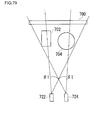
- FIG. 77 shows a relationship among a temporary camera position S (Xs, Ys, Zs) to be set by a producer of three-dimensional data, an angle of view &thetas;, and first to third objects 700, 702 and 704.
- the temporary camera position S (Xs, Ys, Zs) will serve as the center of virtual cameras (hereinafter referred to as center position S of cameras also) when generating the respective parallax images based on a plurality of virtual cameras.
- the first object 700 is equal to the background.
- the producer sets the angle of view &thetas; and the center position S of cameras in such a manner that the second and third objects 702 and 704 are placed within the angle of view &thetas; and at the same time there is object information present in the angle of view &thetas; by the first object 700, which is the background image.
- the first object zero area 740 is alpha , in angle, and the second object zero area 742 is beta , and there is no object information in these angle ranges. Accordingly, as shown in FIG. 79 , the angle of view &thetas; may be adjusted in such a way as to eliminate these alpha and beta. That is, the larger of the values of alpha and beta is subtracted from the angle of view &thetas;.
- FIG. 80 is a flowchart showing a processing for the adjustment of the angle of view.
- This processing for the adjustment of the angle of view can be realized by a first three-dimensional image display apparatus 100 shown in FIG. 11 .
- a camera temporary placement unit 130 determines a center positions S of cameras (S110).
- a camera placement determining unit 132 determines the camera angle of view &thetas; (S112), determines the camera interval E (S114) and determines the optical axis intersecting position A of virtual cameras (S116).
- the above embodiment has been explained mainly in regard to three-dimensional images to be generated from the three-dimensional data.
- the following explanation will concern a technique for expressing three-dimensional images from actually shot images.
- the difference between the case originating from three-dimensional data and the case originating from actually shot images lies in the absence of the concept of the depth T of a basic representation space in the case originating from actually shot images. This can be rephrased as the depth range T capable of appropriate parallax display.
- E, A, &thetas;, S, D and T the rest of the parameters can be calculated. While which of the parameters to specify is generally up to free choice, E, A and D have been calculated by specifying &thetas;, S and T in the previously described embodiment. Automatic change of &thetas; or S may change the enlargement ratio, thus there is concern that the expression intended by a programmer or photographer might not be possible. Therefore, it is often undesirable to determine them automatically. As for T, too, it is desirable to determine it beforehand because it can also be considered a parameter limiting the expressing range. And with three-dimensional data, the trouble of changing any of the parameters is about the same. With actual photography, however, the situation differs. Depending on the structure of cameras, the cost greatly varies and the operability also changes. It is therefore desirable that the parameters to be specified be changed according to the usage.
- FIG. 81 shows a relationship between a three-dimensional photography apparatus 510, which takes stereoscopic photographs in an entertainment facility or photo studio, and an object 552.
- the three-dimensional photography apparatus 510 is structured such that it includes a camera 550 and a three-dimensional image processing apparatus 100.
- the photographic environment is fixed. That is, the positions of the camera 550 and the object 552 are predetermined, and the parameters &thetas;, S and T are determined.
- the example shown in FIG. 18 is replaced by an actual camera 550, and two parallax images, which serve as reference points for a three-dimensional image, can be shot only by this single camera 550, which is provided with two lenses 522 and 524.
- FIG. 82 shows a structure of a sixth three-dimensional image processing apparatus 100 which carries out this processing.
- This three-dimensional image processing apparatus 100 has a camera control unit 151 replacing the parallax detecting unit 150 in the three-dimensional image processing apparatus 100 shown in FIG. 12 .
- the camera control unit 151 includes a lens spacing adjusting unit 153 and an optical axis adjusting unit 155.
- the lens spacing adjusting unit 153 adjusts the camera interval E, or more precisely the lens spacing E, by adjusting the positions of the two lenses 522 and 524.
- the optical axis adjusting unit 155 adjusts D by changing the respective optical axis directions of the two lenses 522 and 524.
- appropriate parallax information of a three-dimensional image display apparatus kept at home or the like is inputted via a portable recording medium such as a memory or card or a means of communication such as the Internet.
- An information acquiring unit 118 receives the input of the appropriate parallax and notifies it to a camera control unit 151.
- the camera control unit 151 Upon receipt of the notification, the camera control unit 151 calculates E, A and D and adjusts the lenses 522 and 524, so that the camera 550 performs a shooting with appropriate parallax. This is accomplished because common processings by the three-dimensional display apparatus to display the object and the three-dimensional photography apparatus 510 are achieved by the library.
- the appropriate parallax information be that checked by the three-dimensional image display apparatus possessed by the user, who is the object.
- a favorite three-dimensional sense may be selected by a typical three-dimensional image display apparatus present at the site of shooting. This selection can be made by a three-dimensional sense adjusting unit 112. Or selection may simply be made from the items, such as "On-screen / Farther position / Nearer position” or "Three-dimensional sense: Large / Intermediate / Small", and predetermined camera parameters stored in correspondence thereto in the parallax information storage unit 120 may be used.
- change of the optical axis intersecting position may be made by a mechanical structure, but it may also be realized by changing the range used as an image by using a high-definition CCD (Charge Coupled Device).
- CCD Charge Coupled Device
- functions of the position shifting unit 160 may be used.
- An operator first operates the optical zoom or electronic zoom using the controller 519 so as to determine &thetas;.
- the camera 550 is moved so as to display an object desired to be shot in the center of the three-dimensional display apparatus 511.
- the camera 550 focuses on an object by an auto-focus mechanism and, at the same time, acquires a distance.
- this distance is D.
- the camera 550 is so set automatically that the object is seen in a position in the vicinity of a display screen.
- the range of T can be manually changed, and the operator specifies the distribution of an object, whose rear-or-front positional relationship is desired to be grasped beforehand, in the depth direction. In this manner, &thetas;, D and T are determined.
- E, A and S are determined by the above-indicated three relational expressions, so that the camera 550 is properly auto-adjusted.
- S is determined later.
- the range of T is uncertain until the final stage. For this reason, T may be set larger to some extent.
- the object may be once displayed in the center and a predetermined button may be depressed so as to be able to fix the focal point and D and, thereafter, the direction of the camera 550 may be changed. If a structure is such that the focal point or D can be manually changed, the depth position of an object can be freely changed.
- the distance to the object can be measured in real time and whether or the calculated distance is appropriate or not can be notified to the photographer via message, color of lamp or the like.
- the distance to the object may be acquired using the known techniques such as a distance measuring function by auto-focusing.
- the mode, for the camera 550 includes a mode where the camera is attached to a microscope, a medical endoscope, a portable terminal or various equipment.
- the apparatus' performance generally is to improve and it is considered to be a rare case that the parallax is too large for a 3D display apparatus purchased next time. Rather, making the adjustment as above is important to prevent a risk in which the stereovision becomes difficult, irrespective of the capability of the 3D display apparatus, due to lack of proper setting. It is assumed here that the 3D display apparatus is structured such that a three-dimensional image processing apparatus is provided therein to realize the stereovision.
- the appropriate parallax obtained by the three-dimensional sense adjusting unit of the first to the sixth three-dimensional image processing apparatus 100 is the parameters, for a particular three-dimensional image processing apparatus 100, determined while the user is viewing three-dimensionally, so that the appropriate parallax is preserved, from then on, in that three-dimensional processing apparatus 100.
- the "image separability" is an objective factor that represents the capability to separate a plurality of viewpoint images.
- the cross talk tends to be easily perceived in the 3D display apparatus, where this capability is low, even if almost no parallax is given, and if a number of viewers make adjustment, the range of the appropriate parallax becomes narrow averagely.
- the image separability is high, the cross talk is hardly perceived even with large parallax given, and the range of the appropriate parallax becomes wide averagely.
- the "physiological limit" is a subjective factor. For example, if the image separability is very high and the image is completely separated, the parallax range in which no sense of discomfort is felt differs depending on viewers. This appears as a variation in the appropriate parallax in the same three-dimensional processing apparatus 100.
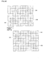
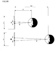
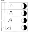
- the image separability is also called the degree of separation and it can be determined by a method in which the illuminance of a reference image 572 is measured while an illuminometer 570 moves in the horizontal direction as shown in FIG. 85 . At that time, in the case of a two-eye type, all is displayed white on the left-eye image whereas all is displayed black on the right-eye image, for example. If an image is completely separated, the illuminance at a place that right eye sees is 0. In contrast thereto, the image separability can be obtained by measuring the degree of leakage of the white in the left-eye image. A graph at the far right of this Figure is an example of the measurement result. Since this measurement is almost equivalent to measuring the shading of moir , the image separability can be measured if a moir image is imported at a distance, where the moir is viewed as in FIG. 86 , and its contrasting density is analyzed.
- the image separability can be measured by measuring the leaked light.
- the calculation may also be done in a manner such that the measured value, obtained when both left and right images are all in black, is taken into account as background.
- the image separability can be determined by an average value of ranking evaluation done by a number of viewers.
- criteria such as objective values can be given for the image the image separability of a 3D display apparatus.
- the appropriate parallax can be converted to suit the rank of a different 3D display apparatus 440.
- the 3D display apparatus there are parameters, serving as characteristic values, such as screen size, pixel pitch and optimum observation distance. And the parameter information such as these is utilized for the conversion of the appropriate parallax.
- N/L is converted to bcN/(aL) and M/L is converted to bcM/(aL) eventually. It is to be noted that this conversion can be applied to parallax either in the horizontal direction or the vertical direction. The above conversion for optimum parallax can be realized in the structures shown in FIG. 52 , FIG. 53 and FIG. 54 .
- the parallax control unit 114 may perform control in such a manner that if parameters, on camera placement, to be set to generate parallax images are changed in the event of generating three-dimensional images by three-dimensional data, the camera parameters fall within threshold values provided beforehand for the variation of the parameters. Moreover, in a case when moving images of three-dimensional images are generated from two-dimensional moving images to which depth information are given, the parallax control unit 114 may perform control so that a variation, caused by progression of the two-dimensional moving images, in a maximum value or minimum value of depth contained in the depth information falls within threshold values provided beforehand. Those threshold values used in the control may be stored in the parallax information storage unit 120.
- the present invention can be utilized for method and apparatus for processing three-dimensional images, and so forth.
Landscapes
- Engineering & Computer Science (AREA)
- Multimedia (AREA)
- Signal Processing (AREA)
- Testing, Inspecting, Measuring Of Stereoscopic Televisions And Televisions (AREA)
- Processing Or Creating Images (AREA)
- Apparatus For Radiation Diagnosis (AREA)
- Stereoscopic And Panoramic Photography (AREA)
- Measuring And Recording Apparatus For Diagnosis (AREA)
- Magnetic Resonance Imaging Apparatus (AREA)
- Endoscopes (AREA)
Applications Claiming Priority (8)
| Application Number | Priority Date | Filing Date | Title |
|---|---|---|---|
| JP2002087496A JP3702243B2 (ja) | 2002-03-27 | 2002-03-27 | 立体画像処理方法および装置 |
| JP2002087497A JP2003284095A (ja) | 2002-03-27 | 2002-03-27 | 立体画像処理方法および装置 |
| JP2002087495A JP2003284093A (ja) | 2002-03-27 | 2002-03-27 | 立体画像処理方法および装置 |
| JP2002087494 | 2002-03-27 | ||
| JP2002087493 | 2002-03-27 | ||
| JP2003003761A JP3749227B2 (ja) | 2002-03-27 | 2003-01-09 | 立体画像処理方法および装置 |
| JP2003003763A JP3857988B2 (ja) | 2002-03-27 | 2003-01-09 | 立体画像処理方法および装置 |
| EP03715473A EP1489857B1 (de) | 2002-03-27 | 2003-03-27 | Verfahren und einrichtung zur dreidimensionalen bildverarbeitung |
Related Parent Applications (1)
| Application Number | Title | Priority Date | Filing Date |
|---|---|---|---|
| EP03715473.9 Division | 2003-03-27 |
Publications (2)
| Publication Number | Publication Date |
|---|---|
| EP2357839A2 true EP2357839A2 (de) | 2011-08-17 |
| EP2357839A3 EP2357839A3 (de) | 2012-02-29 |
Family
ID=28458078
Family Applications (11)
| Application Number | Title | Priority Date | Filing Date |
|---|---|---|---|
| EP11161295.8A Expired - Lifetime EP2357838B1 (de) | 2002-03-27 | 2003-03-27 | Verfahren und Vorrichtung zur Verarbeitung dreidimensionaler Bilder |
| EP11161269A Expired - Lifetime EP2362670B1 (de) | 2002-03-27 | 2003-03-27 | Verfahren und Vorrichtung zur Verarbeitung dreidimensionaler Bilder |
| EP11161274A Withdrawn EP2357835A3 (de) | 2002-03-27 | 2003-03-27 | Verfahren und Vorrichtung zur Verarbeitung dreidimensionaler Bilder |
| EP20110161303 Expired - Lifetime EP2381691B1 (de) | 2002-03-27 | 2003-03-27 | Verfahren und Vorrichtung zur Verarbeitung dreidimensionaler Bilder |
| EP03715473A Expired - Lifetime EP1489857B1 (de) | 2002-03-27 | 2003-03-27 | Verfahren und einrichtung zur dreidimensionalen bildverarbeitung |
| EP11161315A Withdrawn EP2357839A3 (de) | 2002-03-27 | 2003-03-27 | Verfahren und Vorrichtung zur Verarbeitung dreidimensionaler Bilder |
| EP20110161281 Expired - Lifetime EP2357836B1 (de) | 2002-03-27 | 2003-03-27 | Verfahren und Vorrichtung zur Verarbeitung dreidimensionaler Bilder |
| EP11161320A Ceased EP2357840A3 (de) | 2002-03-27 | 2003-03-27 | Verfahren und Vorrichtung zur Verarbeitung dreidimensionaler Bilder |
| EP11161340A Withdrawn EP2387248A3 (de) | 2002-03-27 | 2003-03-27 | Verfahren und Vorrichtung zur Verarbeitung dreidimensionaler Bilder |
| EP11161329.5A Expired - Lifetime EP2357841B1 (de) | 2002-03-27 | 2003-03-27 | Verfahren und Vorrichtung zur Verarbeitung dreidimensionaler Bilder |
| EP11161284A Withdrawn EP2357837A3 (de) | 2002-03-27 | 2003-03-27 | Verfahren und Vorrichtung zur Verarbeitung dreidimensionaler Bilder |
Family Applications Before (5)
| Application Number | Title | Priority Date | Filing Date |
|---|---|---|---|
| EP11161295.8A Expired - Lifetime EP2357838B1 (de) | 2002-03-27 | 2003-03-27 | Verfahren und Vorrichtung zur Verarbeitung dreidimensionaler Bilder |
| EP11161269A Expired - Lifetime EP2362670B1 (de) | 2002-03-27 | 2003-03-27 | Verfahren und Vorrichtung zur Verarbeitung dreidimensionaler Bilder |
| EP11161274A Withdrawn EP2357835A3 (de) | 2002-03-27 | 2003-03-27 | Verfahren und Vorrichtung zur Verarbeitung dreidimensionaler Bilder |
| EP20110161303 Expired - Lifetime EP2381691B1 (de) | 2002-03-27 | 2003-03-27 | Verfahren und Vorrichtung zur Verarbeitung dreidimensionaler Bilder |
| EP03715473A Expired - Lifetime EP1489857B1 (de) | 2002-03-27 | 2003-03-27 | Verfahren und einrichtung zur dreidimensionalen bildverarbeitung |
Family Applications After (5)
| Application Number | Title | Priority Date | Filing Date |
|---|---|---|---|
| EP20110161281 Expired - Lifetime EP2357836B1 (de) | 2002-03-27 | 2003-03-27 | Verfahren und Vorrichtung zur Verarbeitung dreidimensionaler Bilder |
| EP11161320A Ceased EP2357840A3 (de) | 2002-03-27 | 2003-03-27 | Verfahren und Vorrichtung zur Verarbeitung dreidimensionaler Bilder |
| EP11161340A Withdrawn EP2387248A3 (de) | 2002-03-27 | 2003-03-27 | Verfahren und Vorrichtung zur Verarbeitung dreidimensionaler Bilder |
| EP11161329.5A Expired - Lifetime EP2357841B1 (de) | 2002-03-27 | 2003-03-27 | Verfahren und Vorrichtung zur Verarbeitung dreidimensionaler Bilder |
| EP11161284A Withdrawn EP2357837A3 (de) | 2002-03-27 | 2003-03-27 | Verfahren und Vorrichtung zur Verarbeitung dreidimensionaler Bilder |
Country Status (4)
| Country | Link |
|---|---|
| EP (11) | EP2357838B1 (de) |
| KR (1) | KR100812905B1 (de) |
| CN (1) | CN1643939B (de) |
| WO (1) | WO2003081921A1 (de) |
Cited By (2)
| Publication number | Priority date | Publication date | Assignee | Title |
|---|---|---|---|---|
| CN103780894A (zh) * | 2012-10-18 | 2014-05-07 | 财团法人工业技术研究院 | 具视觉疲劳估算的立体影片播放方法与控制系统 |
| US9300942B2 (en) | 2012-10-18 | 2016-03-29 | Industrial Technology Research Institute | Method and control system for three-dimensional video playback using visual fatigue estimation |
Families Citing this family (96)
| Publication number | Priority date | Publication date | Assignee | Title |
|---|---|---|---|---|
| JP4578294B2 (ja) * | 2005-03-18 | 2010-11-10 | 株式会社エヌ・ティ・ティ・データ三洋システム | 立体視画像表示装置、立体視画像表示方法及びコンピュータプログラム |
| EP1875440B1 (de) | 2005-04-19 | 2008-12-03 | Koninklijke Philips Electronics N.V. | Tiefenwahrnehmung |
| KR100739730B1 (ko) | 2005-09-03 | 2007-07-13 | 삼성전자주식회사 | 3d 입체 영상 처리 장치 및 방법 |
| KR101185870B1 (ko) * | 2005-10-12 | 2012-09-25 | 삼성전자주식회사 | 3d 입체 영상 처리 장치 및 방법 |
| KR100704634B1 (ko) | 2005-12-19 | 2007-04-09 | 삼성전자주식회사 | 사용자의 위치에 따른 입체 영상을 디스플레이하는 장치 및방법 |
| KR100762670B1 (ko) * | 2006-06-07 | 2007-10-01 | 삼성전자주식회사 | 스테레오 이미지로부터 디스패리티 맵을 생성하는 방법 및장치와 그를 위한 스테레오 매칭 방법 및 장치 |
| KR101311896B1 (ko) * | 2006-11-14 | 2013-10-14 | 삼성전자주식회사 | 입체 영상의 변위 조정방법 및 이를 적용한 입체 영상장치 |
| TWI331872B (en) | 2006-12-29 | 2010-10-11 | Quanta Comp Inc | Method for displaying stereoscopic image |
| KR101345303B1 (ko) * | 2007-03-29 | 2013-12-27 | 삼성전자주식회사 | 스테레오 또는 다시점 영상의 입체감 조정 방법 및 장치 |
| KR20080100984A (ko) | 2007-05-15 | 2008-11-21 | 삼성전자주식회사 | 3차원 영상 디스플레이 방법 및 장치 |
| US8726194B2 (en) | 2007-07-27 | 2014-05-13 | Qualcomm Incorporated | Item selection using enhanced control |
| KR100906784B1 (ko) * | 2007-11-15 | 2009-07-09 | (주)레드로버 | 입체영상 제작 프로그램용 플러그인 모듈 및 입체영상 제작방법 |
| KR101417024B1 (ko) | 2007-11-22 | 2014-07-08 | 엘지이노텍 주식회사 | 카메라를 이용한 3d 영상 획득 방법 |
| KR100924432B1 (ko) * | 2007-12-06 | 2009-10-29 | 한국전자통신연구원 | 다시점 영상의 인식 깊이감 조절 장치 및 방법 |
| CN101472190B (zh) * | 2007-12-28 | 2013-01-23 | 华为终端有限公司 | 多视角摄像及图像处理装置、系统 |
| WO2009108645A1 (en) * | 2008-02-27 | 2009-09-03 | Sony Computer Entertainment America Inc. | Methods for capturing depth data of a scene and applying computer actions |
| CN106101682B (zh) | 2008-07-24 | 2019-02-22 | 皇家飞利浦电子股份有限公司 | 通用3-d画面格式 |
| JP4657331B2 (ja) | 2008-08-27 | 2011-03-23 | 富士フイルム株式会社 | 3次元表示時における指示位置設定装置および方法並びにプログラム |
| WO2010046824A1 (en) * | 2008-10-21 | 2010-04-29 | Koninklijke Philips Electronics N.V. | Method and system for processing an input three dimensional video signal |
| JP4737573B2 (ja) * | 2009-02-05 | 2011-08-03 | 富士フイルム株式会社 | 3次元画像出力装置及び方法 |
| JP5327524B2 (ja) * | 2009-02-27 | 2013-10-30 | ソニー株式会社 | 画像処理装置、画像処理方法、およびプログラム |
| TW201116041A (en) * | 2009-06-29 | 2011-05-01 | Sony Corp | Three-dimensional image data transmission device, three-dimensional image data transmission method, three-dimensional image data reception device, three-dimensional image data reception method, image data transmission device, and image data reception |
| JP5491786B2 (ja) * | 2009-07-21 | 2014-05-14 | 富士フイルム株式会社 | 画像再生装置及び方法 |
| US8509519B2 (en) * | 2009-07-29 | 2013-08-13 | Intellectual Ventures Fund 83 Llc | Adjusting perspective and disparity in stereoscopic image pairs |
| JP5444955B2 (ja) * | 2009-08-31 | 2014-03-19 | ソニー株式会社 | 立体画像表示システム、視差変換装置、視差変換方法およびプログラム |
| JP5415217B2 (ja) * | 2009-10-02 | 2014-02-12 | パナソニック株式会社 | 三次元映像処理装置 |
| JP5299214B2 (ja) * | 2009-10-20 | 2013-09-25 | ソニー株式会社 | 画像処理装置、および画像処理方法、並びにプログラム |
| JP2011109294A (ja) * | 2009-11-16 | 2011-06-02 | Sony Corp | 情報処理装置、情報処理方法、表示制御装置、表示制御方法、およびプログラム |
| EP2334089A1 (de) * | 2009-12-04 | 2011-06-15 | Alcatel Lucent | Verfahren und Systeme zur Erzeugung eines verbesserten Stereobildes eines Objekts |
| JP5287702B2 (ja) * | 2009-12-25 | 2013-09-11 | ソニー株式会社 | 画像処理装置および方法、並びにプログラム |
| JP2011138354A (ja) * | 2009-12-28 | 2011-07-14 | Sony Corp | 情報処理装置および情報処理方法 |
| KR101759943B1 (ko) | 2010-01-11 | 2017-07-20 | 엘지전자 주식회사 | 방송 수신기 및 3d 이미지 디스플레이 방법 |
| JP4951079B2 (ja) * | 2010-03-11 | 2012-06-13 | 株式会社東芝 | 立体表示装置、映像処理装置 |
| US20130010056A1 (en) * | 2010-03-17 | 2013-01-10 | Kenji Morimoto | Reproduction apparatus |
| KR101487587B1 (ko) * | 2010-04-01 | 2015-01-29 | 노키아 코포레이션 | 입체적 이미징 시점 쌍을 선택하기 위한 방법, 장치 및 컴퓨터 프로그램 |
| EP2375763A2 (de) * | 2010-04-07 | 2011-10-12 | Sony Corporation | Bildverarbeitungsvorrichtung und Bildverarbeitungsverfahren |
| JP5477128B2 (ja) | 2010-04-07 | 2014-04-23 | ソニー株式会社 | 信号処理装置、信号処理方法、表示装置及びプログラム |
| JP2011223481A (ja) * | 2010-04-14 | 2011-11-04 | Sony Corp | データ構造、画像処理装置、画像処理方法、およびプログラム |
| JP5202584B2 (ja) * | 2010-06-24 | 2013-06-05 | 株式会社ソニー・コンピュータエンタテインメント | 画像処理装置、コンテンツ作成支援装置、画像処理方法、コンテンツ作成支援方法、および画像ファイルのデータ構造 |
| KR101829345B1 (ko) * | 2010-06-28 | 2018-02-19 | 톰슨 라이센싱 | 입체 컨텐츠의 3-차원적인 효과들을 요구에 맞추기 위한 방법 및 장치 |
| WO2012001958A1 (ja) * | 2010-06-30 | 2012-01-05 | 富士フイルム株式会社 | 画像処理装置および方法並びにプログラム |
| CN102959968B (zh) * | 2010-06-30 | 2016-05-04 | 富士胶片株式会社 | 图像处理装置、摄像装置及图像处理方法 |
| CN102340678B (zh) * | 2010-07-21 | 2014-07-23 | 深圳Tcl新技术有限公司 | 一种景深可调的立体显示装置及其景深调整方法 |
| CN102986232B (zh) * | 2010-07-26 | 2015-11-25 | 富士胶片株式会社 | 图像处理装置及方法 |
| CN103069814B (zh) | 2010-08-10 | 2016-05-11 | 株式会社尼康 | 图像处理装置、图像处理方法、显示装置、显示方法及程序 |
| EP2434764A1 (de) | 2010-09-23 | 2012-03-28 | Thomson Licensing | Anpassung von 3D-Videoinhalt |
| US8693687B2 (en) * | 2010-10-03 | 2014-04-08 | Himax Media Solutions, Inc. | Method and apparatus of processing three-dimensional video content |
| JP4956658B2 (ja) * | 2010-10-12 | 2012-06-20 | シャープ株式会社 | 立体映像変換装置及び立体映像表示装置 |
| TW201216204A (en) * | 2010-10-13 | 2012-04-16 | Altek Corp | Method for combining dual-lens images into mono-lens image |
| JP2012090094A (ja) * | 2010-10-20 | 2012-05-10 | Sony Corp | 画像処理装置、画像処理方法、およびプログラム |
| US20120113093A1 (en) * | 2010-11-09 | 2012-05-10 | Sharp Laboratories Of America, Inc. | Modification of perceived depth by stereo image synthesis |
| JP5640681B2 (ja) * | 2010-11-11 | 2014-12-17 | ソニー株式会社 | 情報処理装置、立体視表示方法及びプログラム |
| JP5695395B2 (ja) * | 2010-11-19 | 2015-04-01 | インターナショナル・ビジネス・マシーンズ・コーポレーションInternational Business Machines Corporation | 立体画像生成方法及びその装置 |
| WO2012068724A1 (zh) * | 2010-11-23 | 2012-05-31 | 深圳超多维光电子有限公司 | 立体图像获取系统及方法 |
| KR101783608B1 (ko) * | 2010-12-02 | 2017-10-10 | 엘지전자 주식회사 | 전자 장치 및 입체감 조정 방법 |
| CN105898273B (zh) * | 2011-01-07 | 2018-04-10 | 索尼互动娱乐美国有限责任公司 | 二维图像的再投影的多样本解析 |
| EP2574065B1 (de) * | 2011-01-26 | 2016-09-07 | FUJIFILM Corporation | Bildverarbeitungsvorrichtung, bildaufnahmevorrichtung und bildverarbeitungsverfahren |
| RU2476825C2 (ru) * | 2011-03-01 | 2013-02-27 | Государственное образовательное учреждение высшего профессионального образования Томский государственный университет (ТГУ) | Способ управления движущимся объектом и устройство для его осуществления |
| CN102971770B (zh) * | 2011-03-31 | 2016-02-10 | 松下电器产业株式会社 | 进行全周围立体图像的描绘的图像描绘装置、图像描绘方法 |
| CN102740015B (zh) * | 2011-04-13 | 2015-03-11 | 鸿富锦精密工业(深圳)有限公司 | 同时播放不同频道的电视系统 |
| BR112013027226A2 (pt) | 2011-04-28 | 2016-12-27 | Panasonic Corp | dispositivo de processamento de vídeo e método de processamento de vídeo |
| US20120300034A1 (en) * | 2011-05-23 | 2012-11-29 | Qualcomm Incorporated | Interactive user interface for stereoscopic effect adjustment |
| JP2012247891A (ja) * | 2011-05-26 | 2012-12-13 | Sony Corp | 画像処理装置、画像処理方法、およびプログラム |
| JP5971632B2 (ja) * | 2011-05-26 | 2016-08-17 | パナソニックIpマネジメント株式会社 | 電子機器および合成画像の編集方法 |
| KR20120133951A (ko) * | 2011-06-01 | 2012-12-11 | 삼성전자주식회사 | 3d 영상변환장치 그 깊이정보 조정방법 및 그 저장매체 |
| TWI486052B (zh) * | 2011-07-05 | 2015-05-21 | Realtek Semiconductor Corp | 立體影像處理裝置以及立體影像處理方法 |
| CN103037236A (zh) * | 2011-08-22 | 2013-04-10 | 联发科技股份有限公司 | 图像处理方法以及装置 |
| WO2013031155A1 (ja) * | 2011-08-30 | 2013-03-07 | パナソニック株式会社 | 撮像装置 |
| US9402065B2 (en) | 2011-09-29 | 2016-07-26 | Qualcomm Incorporated | Methods and apparatus for conditional display of a stereoscopic image pair |
| KR101888155B1 (ko) * | 2011-11-22 | 2018-08-16 | 삼성전자주식회사 | 디스플레이 장치 및 그 디스플레이 방법 |
| CN102413350B (zh) * | 2011-11-30 | 2014-04-16 | 四川长虹电器股份有限公司 | 蓝光3d视频处理方法 |
| JP5818674B2 (ja) * | 2011-12-21 | 2015-11-18 | 株式会社東芝 | 画像処理装置、方法、及びプログラム、並びに、画像表示装置 |
| CN103227929B (zh) * | 2012-01-29 | 2016-10-26 | 晨星软件研发(深圳)有限公司 | 立体影像处理装置及立体影像处理方法 |
| DE102012201564B3 (de) * | 2012-02-02 | 2013-05-29 | Leica Microsystems (Schweiz) Ag | System zur Darstellung stereoskopischer Bilder |
| US8855442B2 (en) * | 2012-04-30 | 2014-10-07 | Yuri Owechko | Image registration of multimodal data using 3D-GeoArcs |
| CN102752621A (zh) * | 2012-06-26 | 2012-10-24 | 京东方科技集团股份有限公司 | 景深保持装置、3d显示装置及显示方法 |
| EP2680593A1 (de) | 2012-06-26 | 2014-01-01 | Thomson Licensing | Verfahren zur Anpassung eines 3D-Inhalts an einen Betrachter mit Brille |
| US9661296B2 (en) | 2012-07-12 | 2017-05-23 | Samsung Electronics Co., Ltd. | Image processing apparatus and method |
| CN103686118A (zh) * | 2012-09-19 | 2014-03-26 | 珠海扬智电子科技有限公司 | 影像深度调整方法与装置 |
| JP5903023B2 (ja) * | 2012-10-04 | 2016-04-13 | 株式会社ジオ技術研究所 | 立体視地図表示システム |
| RU2525228C2 (ru) * | 2012-10-19 | 2014-08-10 | Федеральное бюджетное учреждение "3 Центральный научно-исследовательский институт Министерства обороны Российской Федерации" | Устройство локации и навигации |
| JP2014230251A (ja) * | 2013-05-27 | 2014-12-08 | ソニー株式会社 | 画像処理装置、および画像処理方法 |
| CN103458259B (zh) * | 2013-08-27 | 2016-04-13 | Tcl集团股份有限公司 | 一种3d视频引起人眼疲劳度的检测方法、装置及系统 |
| KR101528683B1 (ko) * | 2013-11-29 | 2015-06-15 | 영산대학교산학협력단 | 과도시차 객체 검출방법 |
| CN103686416B (zh) * | 2013-12-27 | 2016-09-28 | 乐视致新电子科技(天津)有限公司 | 智能电视中的3d设置信息处理方法及装置 |
| TW201528775A (zh) | 2014-01-02 | 2015-07-16 | Ind Tech Res Inst | 景深圖校正方法及系統 |
| US9667951B2 (en) | 2014-02-18 | 2017-05-30 | Cisco Technology, Inc. | Three-dimensional television calibration |
| CN103841403B (zh) * | 2014-03-11 | 2015-12-02 | 福州大学 | 一种无形变立体图像视差快速调节方法 |
| CN104284177A (zh) * | 2014-10-28 | 2015-01-14 | 天津大学 | 会聚立体图像视差控制方法 |
| KR101817436B1 (ko) * | 2016-08-02 | 2018-02-21 | 연세대학교 산학협력단 | 안구 전위 센서를 이용한 영상 표시 장치 및 제어 방법 |
| JP6780983B2 (ja) * | 2016-08-18 | 2020-11-04 | マクセル株式会社 | 画像処理システム |
| RU2672092C1 (ru) * | 2017-07-19 | 2018-11-12 | Федеральное государственное бюджетное образовательное учреждение высшего образования "Московский авиационный институт (национальный исследовательский университет)" | Способ измерения углового положения наземных неподвижных радиоконтрастных объектов |
| WO2021063919A1 (en) * | 2019-09-30 | 2021-04-08 | Interdigital Vc Holdings France, Sas | Method and apparatus for processing image content |
| CN113343207A (zh) * | 2021-06-07 | 2021-09-03 | 网易(杭州)网络有限公司 | 信息验证的方法、装置、计算机设备及存储介质 |
| KR102317230B1 (ko) * | 2021-08-25 | 2021-10-26 | 주식회사 에스에이엠지엔터테인먼트 | 인공지능 기반 아케이드 게임 환경 확장 시스템 |
| KR20230053956A (ko) | 2021-10-15 | 2023-04-24 | 김채은 | 잉크 찌꺼기가 나오지 않는 더 매끄러운 쇠볼을 가진 볼펜 |
Citations (1)
| Publication number | Priority date | Publication date | Assignee | Title |
|---|---|---|---|---|
| JPH01139507A (ja) | 1987-11-25 | 1989-06-01 | Hitachi Ltd | ドライフラワ輸送容器 |
Family Cites Families (21)
| Publication number | Priority date | Publication date | Assignee | Title |
|---|---|---|---|---|
| US5502481A (en) * | 1992-11-16 | 1996-03-26 | Reveo, Inc. | Desktop-based projection display system for stereoscopic viewing of displayed imagery over a wide field of view |
| JPH0568268A (ja) * | 1991-03-04 | 1993-03-19 | Sharp Corp | 立体視画像作成装置および立体視画像作成方法 |
| EP0641132B1 (de) * | 1993-08-26 | 1999-04-14 | Matsushita Electric Industrial Co., Ltd. | Stereoskopischer Abtastapparat |
| JPH07298307A (ja) * | 1994-04-28 | 1995-11-10 | Canon Inc | 画像記録再生装置 |
| JP3157384B2 (ja) * | 1994-06-20 | 2001-04-16 | 三洋電機株式会社 | 立体映像装置 |
| KR100414629B1 (ko) * | 1995-03-29 | 2004-05-03 | 산요덴키가부시키가이샤 | 3차원표시화상생성방법,깊이정보를이용한화상처리방법,깊이정보생성방법 |
| US6005607A (en) * | 1995-06-29 | 1999-12-21 | Matsushita Electric Industrial Co., Ltd. | Stereoscopic computer graphics image generating apparatus and stereoscopic TV apparatus |
| JPH09271043A (ja) * | 1996-03-29 | 1997-10-14 | Olympus Optical Co Ltd | 立体映像ディスプレイ装置 |
| US6163337A (en) * | 1996-04-05 | 2000-12-19 | Matsushita Electric Industrial Co., Ltd. | Multi-view point image transmission method and multi-view point image display method |
| GB9611938D0 (en) * | 1996-06-07 | 1996-08-07 | Philips Electronics Nv | Stereo image generation |
| EP2175666B1 (de) * | 1996-12-04 | 2012-11-14 | Panasonic Corporation | Optische Platte für hochauflösende und dreidimensionale Videoaufzeichnung, Wiedergabegerät für optische Platten, und Aufzeichnungsgerät für optische Platten |
| JP3500056B2 (ja) * | 1997-11-10 | 2004-02-23 | 三洋電機株式会社 | 2次元映像を3次元映像に変換する装置および方法 |
| MY124160A (en) * | 1997-12-05 | 2006-06-30 | Dynamic Digital Depth Res Pty | Improved image conversion and encoding techniques |
| JP2000209614A (ja) * | 1999-01-14 | 2000-07-28 | Sony Corp | 立体映像システム |
| AUPQ119799A0 (en) * | 1999-06-25 | 1999-07-22 | Dynamic Digital Depth Research Pty Ltd | Ddc/3 image conversion and encoding techniques |
| ATE278298T1 (de) * | 1999-11-26 | 2004-10-15 | Sanyo Electric Co | Verfahren zur 2d/3d videoumwandlung |
| JP2001218228A (ja) * | 2000-02-01 | 2001-08-10 | Canon Inc | 立体画像撮影用光学系及びそれを用いた立体画像撮影装置 |
| JP2001326947A (ja) * | 2000-05-12 | 2001-11-22 | Sony Corp | 立体画像表示装置 |
| US7200261B2 (en) * | 2000-08-25 | 2007-04-03 | Fujifilm Corporation | Parallax image capturing apparatus and parallax image processing apparatus |
| JP2002095018A (ja) * | 2000-09-12 | 2002-03-29 | Canon Inc | 画像表示制御装置及び画像表示システム、並びに画像データの表示方法 |
| KR20020077692A (ko) * | 2001-04-02 | 2002-10-14 | 에이디아이 코퍼레이션 | 입체영상을 발생시키는 방법 및 장치 |
-
2003
- 2003-03-27 WO PCT/JP2003/003791 patent/WO2003081921A1/ja not_active Ceased
- 2003-03-27 EP EP11161295.8A patent/EP2357838B1/de not_active Expired - Lifetime
- 2003-03-27 EP EP11161269A patent/EP2362670B1/de not_active Expired - Lifetime
- 2003-03-27 EP EP11161274A patent/EP2357835A3/de not_active Withdrawn
- 2003-03-27 EP EP20110161303 patent/EP2381691B1/de not_active Expired - Lifetime
- 2003-03-27 CN CN038071592A patent/CN1643939B/zh not_active Expired - Fee Related
- 2003-03-27 EP EP03715473A patent/EP1489857B1/de not_active Expired - Lifetime
- 2003-03-27 KR KR1020047015105A patent/KR100812905B1/ko not_active Expired - Fee Related
- 2003-03-27 EP EP11161315A patent/EP2357839A3/de not_active Withdrawn
- 2003-03-27 EP EP20110161281 patent/EP2357836B1/de not_active Expired - Lifetime
- 2003-03-27 EP EP11161320A patent/EP2357840A3/de not_active Ceased
- 2003-03-27 EP EP11161340A patent/EP2387248A3/de not_active Withdrawn
- 2003-03-27 EP EP11161329.5A patent/EP2357841B1/de not_active Expired - Lifetime
- 2003-03-27 EP EP11161284A patent/EP2357837A3/de not_active Withdrawn
Patent Citations (1)
| Publication number | Priority date | Publication date | Assignee | Title |
|---|---|---|---|---|
| JPH01139507A (ja) | 1987-11-25 | 1989-06-01 | Hitachi Ltd | ドライフラワ輸送容器 |
Cited By (3)
| Publication number | Priority date | Publication date | Assignee | Title |
|---|---|---|---|---|
| CN103780894A (zh) * | 2012-10-18 | 2014-05-07 | 财团法人工业技术研究院 | 具视觉疲劳估算的立体影片播放方法与控制系统 |
| CN103780894B (zh) * | 2012-10-18 | 2016-02-10 | 财团法人工业技术研究院 | 具视觉疲劳估算的立体影片播放方法与控制系统 |
| US9300942B2 (en) | 2012-10-18 | 2016-03-29 | Industrial Technology Research Institute | Method and control system for three-dimensional video playback using visual fatigue estimation |
Also Published As
| Publication number | Publication date |
|---|---|
| CN1643939A (zh) | 2005-07-20 |
| KR100812905B1 (ko) | 2008-03-11 |
| EP2357841A3 (de) | 2012-02-22 |
| EP2357837A3 (de) | 2012-02-22 |
| EP2381691A2 (de) | 2011-10-26 |
| EP2357838A2 (de) | 2011-08-17 |
| EP2362670A1 (de) | 2011-08-31 |
| EP2357838B1 (de) | 2016-03-16 |
| EP2357836A3 (de) | 2012-03-07 |
| EP2357837A2 (de) | 2011-08-17 |
| CN1643939B (zh) | 2010-10-06 |
| EP1489857A1 (de) | 2004-12-22 |
| EP2381691B1 (de) | 2015-05-13 |
| EP2357838A3 (de) | 2012-02-22 |
| EP2357835A3 (de) | 2012-02-22 |
| KR20050004823A (ko) | 2005-01-12 |
| EP2362670B1 (de) | 2012-10-03 |
| EP2381691A3 (de) | 2012-05-23 |
| EP2357841A2 (de) | 2011-08-17 |
| EP2357840A2 (de) | 2011-08-17 |
| EP2387248A2 (de) | 2011-11-16 |
| EP2357836A2 (de) | 2011-08-17 |
| EP1489857B1 (de) | 2011-12-14 |
| EP2387248A3 (de) | 2012-03-07 |
| EP2357836B1 (de) | 2015-05-13 |
| EP2357840A3 (de) | 2012-02-29 |
| WO2003081921A1 (en) | 2003-10-02 |
| EP2357835A2 (de) | 2011-08-17 |
| EP2357839A3 (de) | 2012-02-29 |
| EP1489857A4 (de) | 2007-07-25 |
| EP2357841B1 (de) | 2015-07-22 |
Similar Documents
| Publication | Publication Date | Title |
|---|---|---|
| EP2381691B1 (de) | Verfahren und Vorrichtung zur Verarbeitung dreidimensionaler Bilder | |
| US8131064B2 (en) | Method and apparatus for processing three-dimensional images | |
| JP3749227B2 (ja) | 立体画像処理方法および装置 | |
| JP2004221700A (ja) | 立体画像処理方法および装置 | |
| JP3857988B2 (ja) | 立体画像処理方法および装置 | |
| JP2003284093A (ja) | 立体画像処理方法および装置 | |
| JP2004221699A (ja) | 立体画像処理方法および装置 | |
| JP4118146B2 (ja) | 立体画像処理装置 | |
| JP2003284094A (ja) | 立体画像処理方法および装置 |
Legal Events
| Date | Code | Title | Description |
|---|---|---|---|
| PUAI | Public reference made under article 153(3) epc to a published international application that has entered the european phase |
Free format text: ORIGINAL CODE: 0009012 |
|
| AC | Divisional application: reference to earlier application |
Ref document number: 1489857 Country of ref document: EP Kind code of ref document: P |
|
| AK | Designated contracting states |
Kind code of ref document: A2 Designated state(s): DE FR GB |
|
| PUAL | Search report despatched |
Free format text: ORIGINAL CODE: 0009013 |
|
| AK | Designated contracting states |
Kind code of ref document: A3 Designated state(s): DE FR GB |
|
| RIC1 | Information provided on ipc code assigned before grant |
Ipc: H04N 13/00 20060101AFI20120120BHEP |
|
| STAA | Information on the status of an ep patent application or granted ep patent |
Free format text: STATUS: THE APPLICATION IS DEEMED TO BE WITHDRAWN |
|
| 18D | Application deemed to be withdrawn |
Effective date: 20120830 |