EP2360349A2 - Aube statorique de turbine à vapeur ayant une interface arquée - Google Patents
Aube statorique de turbine à vapeur ayant une interface arquée Download PDFInfo
- Publication number
- EP2360349A2 EP2360349A2 EP11154455A EP11154455A EP2360349A2 EP 2360349 A2 EP2360349 A2 EP 2360349A2 EP 11154455 A EP11154455 A EP 11154455A EP 11154455 A EP11154455 A EP 11154455A EP 2360349 A2 EP2360349 A2 EP 2360349A2
- Authority
- EP
- European Patent Office
- Prior art keywords
- sidewall
- steam turbine
- arcuate
- static nozzle
- airfoil
- Prior art date
- Legal status (The legal status is an assumption and is not a legal conclusion. Google has not performed a legal analysis and makes no representation as to the accuracy of the status listed.)
- Withdrawn
Links
- 230000003068 static effect Effects 0.000 claims abstract description 86
- 230000000295 complement effect Effects 0.000 claims description 10
- 238000003466 welding Methods 0.000 description 7
- 238000005219 brazing Methods 0.000 description 5
- 239000002184 metal Substances 0.000 description 4
- 229910052751 metal Inorganic materials 0.000 description 4
- 238000003754 machining Methods 0.000 description 3
- 238000005266 casting Methods 0.000 description 2
- 239000012530 fluid Substances 0.000 description 2
- 238000005242 forging Methods 0.000 description 2
- 238000002844 melting Methods 0.000 description 2
- 230000008018 melting Effects 0.000 description 2
- 150000002739 metals Chemical class 0.000 description 2
- 238000000034 method Methods 0.000 description 2
- 239000010953 base metal Substances 0.000 description 1
- 239000000945 filler Substances 0.000 description 1
- 238000010438 heat treatment Methods 0.000 description 1
- 239000000463 material Substances 0.000 description 1
Images



Classifications
-
- F—MECHANICAL ENGINEERING; LIGHTING; HEATING; WEAPONS; BLASTING
- F01—MACHINES OR ENGINES IN GENERAL; ENGINE PLANTS IN GENERAL; STEAM ENGINES
- F01D—NON-POSITIVE DISPLACEMENT MACHINES OR ENGINES, e.g. STEAM TURBINES
- F01D9/00—Stators
- F01D9/02—Nozzles; Nozzle boxes; Stator blades; Guide conduits, e.g. individual nozzles
- F01D9/04—Nozzles; Nozzle boxes; Stator blades; Guide conduits, e.g. individual nozzles forming ring or sector
- F01D9/042—Nozzles; Nozzle boxes; Stator blades; Guide conduits, e.g. individual nozzles forming ring or sector fixing blades to stators
-
- F—MECHANICAL ENGINEERING; LIGHTING; HEATING; WEAPONS; BLASTING
- F01—MACHINES OR ENGINES IN GENERAL; ENGINE PLANTS IN GENERAL; STEAM ENGINES
- F01D—NON-POSITIVE DISPLACEMENT MACHINES OR ENGINES, e.g. STEAM TURBINES
- F01D5/00—Blades; Blade-carrying members; Heating, heat-insulating, cooling or antivibration means on the blades or the members
- F01D5/12—Blades
- F01D5/14—Form or construction
- F01D5/147—Construction, i.e. structural features, e.g. of weight-saving hollow blades
-
- F—MECHANICAL ENGINEERING; LIGHTING; HEATING; WEAPONS; BLASTING
- F01—MACHINES OR ENGINES IN GENERAL; ENGINE PLANTS IN GENERAL; STEAM ENGINES
- F01D—NON-POSITIVE DISPLACEMENT MACHINES OR ENGINES, e.g. STEAM TURBINES
- F01D9/00—Stators
- F01D9/02—Nozzles; Nozzle boxes; Stator blades; Guide conduits, e.g. individual nozzles
- F01D9/04—Nozzles; Nozzle boxes; Stator blades; Guide conduits, e.g. individual nozzles forming ring or sector
- F01D9/042—Nozzles; Nozzle boxes; Stator blades; Guide conduits, e.g. individual nozzles forming ring or sector fixing blades to stators
- F01D9/044—Nozzles; Nozzle boxes; Stator blades; Guide conduits, e.g. individual nozzles forming ring or sector fixing blades to stators permanently, e.g. by welding, brazing, casting or the like
-
- F—MECHANICAL ENGINEERING; LIGHTING; HEATING; WEAPONS; BLASTING
- F05—INDEXING SCHEMES RELATING TO ENGINES OR PUMPS IN VARIOUS SUBCLASSES OF CLASSES F01-F04
- F05D—INDEXING SCHEME FOR ASPECTS RELATING TO NON-POSITIVE-DISPLACEMENT MACHINES OR ENGINES, GAS-TURBINES OR JET-PROPULSION PLANTS
- F05D2220/00—Application
- F05D2220/30—Application in turbines
- F05D2220/31—Application in turbines in steam turbines
-
- F—MECHANICAL ENGINEERING; LIGHTING; HEATING; WEAPONS; BLASTING
- F05—INDEXING SCHEMES RELATING TO ENGINES OR PUMPS IN VARIOUS SUBCLASSES OF CLASSES F01-F04
- F05D—INDEXING SCHEME FOR ASPECTS RELATING TO NON-POSITIVE-DISPLACEMENT MACHINES OR ENGINES, GAS-TURBINES OR JET-PROPULSION PLANTS
- F05D2230/00—Manufacture
- F05D2230/20—Manufacture essentially without removing material
- F05D2230/23—Manufacture essentially without removing material by permanently joining parts together
- F05D2230/232—Manufacture essentially without removing material by permanently joining parts together by welding
-
- F—MECHANICAL ENGINEERING; LIGHTING; HEATING; WEAPONS; BLASTING
- F05—INDEXING SCHEMES RELATING TO ENGINES OR PUMPS IN VARIOUS SUBCLASSES OF CLASSES F01-F04
- F05D—INDEXING SCHEME FOR ASPECTS RELATING TO NON-POSITIVE-DISPLACEMENT MACHINES OR ENGINES, GAS-TURBINES OR JET-PROPULSION PLANTS
- F05D2230/00—Manufacture
- F05D2230/20—Manufacture essentially without removing material
- F05D2230/23—Manufacture essentially without removing material by permanently joining parts together
- F05D2230/232—Manufacture essentially without removing material by permanently joining parts together by welding
- F05D2230/237—Brazing
-
- F—MECHANICAL ENGINEERING; LIGHTING; HEATING; WEAPONS; BLASTING
- F05—INDEXING SCHEMES RELATING TO ENGINES OR PUMPS IN VARIOUS SUBCLASSES OF CLASSES F01-F04
- F05D—INDEXING SCHEME FOR ASPECTS RELATING TO NON-POSITIVE-DISPLACEMENT MACHINES OR ENGINES, GAS-TURBINES OR JET-PROPULSION PLANTS
- F05D2250/00—Geometry
- F05D2250/20—Three-dimensional
- F05D2250/23—Three-dimensional prismatic
- F05D2250/232—Three-dimensional prismatic conical
-
- F—MECHANICAL ENGINEERING; LIGHTING; HEATING; WEAPONS; BLASTING
- F05—INDEXING SCHEMES RELATING TO ENGINES OR PUMPS IN VARIOUS SUBCLASSES OF CLASSES F01-F04
- F05D—INDEXING SCHEME FOR ASPECTS RELATING TO NON-POSITIVE-DISPLACEMENT MACHINES OR ENGINES, GAS-TURBINES OR JET-PROPULSION PLANTS
- F05D2250/00—Geometry
- F05D2250/70—Shape
- F05D2250/71—Shape curved
- F05D2250/711—Shape curved convex
-
- F—MECHANICAL ENGINEERING; LIGHTING; HEATING; WEAPONS; BLASTING
- F05—INDEXING SCHEMES RELATING TO ENGINES OR PUMPS IN VARIOUS SUBCLASSES OF CLASSES F01-F04
- F05D—INDEXING SCHEME FOR ASPECTS RELATING TO NON-POSITIVE-DISPLACEMENT MACHINES OR ENGINES, GAS-TURBINES OR JET-PROPULSION PLANTS
- F05D2250/00—Geometry
- F05D2250/70—Shape
- F05D2250/71—Shape curved
- F05D2250/712—Shape curved concave
Definitions
- the subject matter disclosed herein relates to a steam turbine nozzle assembly, or diaphragm stage. Specifically, the subject matter disclosed herein relates to a steam turbine nozzle assembly including a plurality of nozzle segments with arcuate or "conical” (e.g., arced concave, arced convex) interfaces.
- arcuate or "conical” e.g., arced concave, arced convex
- Steam turbines include static nozzle (or "airfoil”) segments that direct flow of a working fluid into turbine buckets connected to a rotating rotor.
- a complete assembly of nozzle segments is commonly referred to as a diaphragm stage of the steam turbine.
- One method of constructing the diaphragm stage is to weld (or alternatively, braze) a plurality of single airfoils with integrated sidewalls ("static nozzle blades", or “singlets”) to inner and outer rings.
- static nozzle blades or “singlets”
- interfaces include an axial leading edge section (or “pressure-side” section) oriented parallel to the steam turbine's axis, and an angled trailing edge section (or “suction-side” section). While the current singlet design including angled interface sections allows for a tight fit between individual segments, the angled interfaces make removal and repair of individual segments nearly impossible.
- a steam turbine static nozzle blade includes: an airfoil; an inner sidewall integral with a first side of the airfoil; and an outer sidewall integral with a second side of the airfoil; the inner sidewall and the outer sidewall each including: a pressure side having an arcuate concave surface extending substantially an entire length of the sidewall; and a suction side having an arcuate convex surface extending substantially the entire length of the sidewall.
- a first aspect of the invention includes a steam turbine static nozzle blade comprising: an airfoil; an inner sidewall integral with a first side of the airfoil; and an outer sidewall integral with a second side of the airfoil; the inner sidewall and the outer sidewall each including: a pressure side having an arcuate concave surface extending substantially an entire length of the sidewall; and a suction side having an arcuate convex surface extending substantially the entire length of the sidewall.
- a second aspect of the invention includes a steam turbine diaphragm assembly comprising: an outer diaphragm ring; an inner diaphragm ring; and an annulus of static nozzle blades between the inner diaphragm ring and the outer diaphragm ring, each static nozzle blade comprising: an airfoil; an inner sidewall integral with a first side of the airfoil; and an outer sidewall integral with a second side of the airfoil; the inner sidewall and the outer sidewall each including: a pressure side having an arcuate concave surface extending substantially an entire length of the sidewall; and a suction side having an arcuate convex surface extending substantially the entire length of the sidewall; wherein at least one of the static nozzle blades is demountably attached to a second one of the static nozzle blades.
- a third aspect of the invention includes a steam turbine diaphragm assembly comprising: an outer diaphragm ring; an inner diaphragm ring; and an annulus of static nozzle blades between the inner diaphragm ring and the outer diaphragm ring, each static nozzle blade comprising: an airfoil; an inner sidewall integral with a first side of the airfoil; and an outer sidewall integral with a second side of the airfoil; the inner sidewall and the outer sidewall each including: a pressure side having an arcuate concave surface extending substantially an entire length of the sidewall; and a suction side having an arcuate convex surface extending substantially the entire length of the sidewall, wherein at least one of the static nozzle blades is demountably attached to a second one of the static nozzle blades in an axial direction; and a plurality of removable weld joints, each removable weld joint substantially removably affixing one of the static nozzle blades to one
- aspects of the invention provide for a steam turbine nozzle segment having a conical interface.
- aspects of the invention provide for a steam turbine nozzle assembly including a plurality of nozzle segments with arcuate or "conical” (e.g., arced concave, arced convex) interfaces. These arced interfaces may allow for removal and/or repair of individual nozzle segments while substantially maintaining the structural integrity of the nozzle assembly.
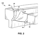
- FIGS. 1-2 show a nozzle assembly 100 for a steam turbine (not shown).
- FIG. 1 shows a plan view of nozzle assembly 100
- FIG. 2 shows a three-dimensional schematic of nozzle assembly 100.
- Nozzle assembly 100 includes a static nozzle blade 10 including at least one airfoil 12 having an inner sidewall 14 and an outer sidewall 16.
- Nozzle assembly 100 further includes an inner ring 18 and an outer ring 20.
- Inner and outer refer to a radial position relative to a rotor (not shown) to which an inner end of airfoil 12 is coupled via inner ring 18.
- Inner ring 18 and inner sidewall 14 are coupled together at an interface 80, which is understood to refer to the entire area where the rings and sidewall are adjacent and coupled.
- Inner ring 18 and inner sidewall 14 are welded (or alternatively, brazed) together at several points at interface 80 ( FIG. 1 ).
- brazing may be performed as an alternative to welding.
- welding and brazing may be used to join metals together.
- welding may be performed by melting and fusing metals together, usually by adding a filler material.
- Brazing by contrast, usually does not involve melting the base metals being joined, and is usually performed at lower temperatures than welding. While metal joints are described herein as “weld joints”, it is understood that these metal joints may alternatively be described as "braze joints.”
- Interfaces 80 between rings 18, 20 and sidewalls 14, 16 may each include a mechanical radial stop 19 which maintains airfoil 12 in the correct radial position during welding and prevents weld shrinkage.
- Interfaces 80 each may further include a mechanical axial stop 17 which maintains airfoil 12 in the correct axial position and controls the weld length depth.
- the nozzle assembly 100 of FIG. 2 is shown, further including a plurality of static nozzle blades 10 arranged in a portion of a diaphragm assembly (full assembly omitted for clarity).
- sidewalls 14, 16 of static nozzle blades 10 may include angled interfaces 34 (e.g., a "dogleg" interface including two surfaces oriented at obtuse angles). These angled interfaces 34 may allow for a plurality of static nozzle blades to be arranged substantially flush with one another in nozzle assembly 100.
- the plurality of static nozzle blades 10 are held within inner 18 and outer sidewalls 20 via the plurality of welds 90.
- Static nozzle blade 110 may include an airfoil 112, an inner sidewall 114, and an outer sidewall 116.
- inner sidewall 114 may be integral with a first side of the airfoil 112 (e.g., via machining from a forging or block, welding, casting, brazing, etc.)
- outer sidewall 116 may be integral with a second side of the airfoil 112 (e.g., via machining from a forging or block, welding, casting, brazing, etc.).
- the inner sidewall 114 and the outer sidewall 116 may each include a pressure side 124 and a suction side 126.
- pressure side and suction side correspond to the pressure side and suction side of airfoil 112, respectively.
- the pressure side of airfoil 112 is the high-pressure side designed to guide the flow of a working fluid through the static nozzle blade 110.
- the suction side of airfoil 112 is the lower-pressure side substantially opposing the pressure side.
- Each pressure side 124 may have an arcuate concave surface 134
- each suction side 126 may have an arcuate convex surface 136.
- the arcuate concave surface 134 may extend substantially an entire length L of the sidewall 114, 116, respectively, and the arcuate convex surface 136 may extend substantially the entire length L of the sidewall 114, 116, respectively.
- the arcuate concave surface 134 of the inner sidewall 114 has a substantially equal arc radius to the arcuate convex surface 136 of the inner sidewall 114.
- the arcuate concave surface 134 of the outer sidewall 116 and the arcuate convex surface 136 of the outer sidewall 116 may have a substantially equal arc radius.
- the arcuate concave surfaces 134 of the inner sidewall 114 and outer sidewall 116, respectively may have substantially equal arc lengths as the arcuate convex surfaces 136 of the inner sidewall 114 and outer sidewall 116, respectively.
- the arcuate concave surface 134 of the inner sidewall 114 and the arcuate concave surface 134 of the outer sidewall 116 complement the arcuate convex surface 136 of the inner sidewall 114 and the arcuate convex surface 136 of the outer sidewall 116, respectively. That is, in an arrangement including more than one steam turbine static nozzle blade 110 ( FIGS. 5-7 ), the arcuate convex surface 136 of an inner sidewall 114 of a first steam turbine static nozzle blade 110 complements the arcuate concave surface 134 of an inner sidewall 114 on a second similar steam turbine static nozzle blade 110.
- arcuate convex surface 136 of an outer sidewall 116 of a first steam turbine static nozzle blade 110 complements the arcuate concave surface 134 of an outer sidewall 116 on a second similar steam turbine static nozzle blade 110.
- the term “complement(s)” refers to a relationship between surfaces in which portions of those surfaces may be arranged substantially flush with one another.
- pressure-side (arcuate concave) surfaces and suction-side (arcuate convex) surfaces may be arranged in a steam turbine diaphragm assembly ( FIG.
- each of the respective (inner, outer) arcuate concave surfaces of a first steam turbine static nozzle blade 110 are substantially flush with the respective (inner, outer) arcuate convex surfaces of a second steam turbine static nozzle blade 110.
- the relationship between pressure-side surfaces and suction-side surfaces is further explained with reference to FIGS. 5-7 .
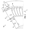
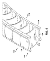
- FIGS. 5 and 6 arrangements including a plurality of substantially similar steam turbine static nozzle blades 110 are shown.
- steam turbine static nozzle blades 110 may be arranged such that their complementary surfaces (arcuate concave surfaces 134 and arcuate convex surfaces 136, respectively) are substantially flush with one another. This may allow for, among other things, efficient feeding of steam across airfoils 112 and mechanical stability.
- FIG. 5 shows an arrangement including the plurality of steam turbine static nozzle blades 110 of FIG. 5 , along with additional substantially similar blades, forming part of a steam turbine diaphragm assembly (diaphragm rings omitted). As described with respect to FIG. 5 , and shown more clearly in FIG.
- part of a steam turbine diaphragm assembly may be formed by arranging complementary conical surfaces of steam turbine static nozzle blades 110 flush with one another.
- the plurality of steam turbine static nozzle blades 110 may be demountably attached to one another in an axial direction (denoted by "A"). This demountable attachment may allow for axial removal of one or more steam turbine static nozzle blades 110 from the assembly without substantially disturbing the structural integrity (e.g., weld joints 190) of the remainder of the assembly.
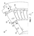
- portion of a steam turbine diaphragm assembly 200 is shown according to an embodiment.
- Portion of steam turbine diaphragm assembly 200 may include a plurality of steam turbine static nozzle blades 110 arranged with substantially flush complementary surfaces as described with reference to FIGS. 5-6 .
- portion of steam turbine diaphragm assembly 200 may include an inner diaphragm ring 118 and an outer diaphragm ring 120, which may be substantially similar to those inner and outer rings (18 and 20) shown and described with reference to FIGS. 1-3 .
- the plurality of steam turbine static nozzle blades 110 may form an annulus between the inner diaphragm ring 118 and the outer diaphragm ring 120.
- plurality of steam turbine static nozzle blades 110 may be demountably attached to one another.
- the plurality of steam turbine static nozzle blades 110 may be substantially removably affixed to at least one of the inner diaphragm ring 118 and outer diaphragm ring 120 via the plurality of removable weld joints 190.
- a steam turbine static nozzle blade 110 may be removed from the steam turbine diaphragm assembly 200 without removing weld joints 190 of one or more adjacent steam turbine static nozzle blades 110.
- each steam turbine static nozzle blade 110 that is not welded to one of the inner diaphragm ring 118 and outer diaphragm ring 120 may be removed or inserted between two fixed (e.g., welded) steam turbine static nozzle blades 110 in the axial direction (A).
- each steam turbine static nozzle blade 110 may be demountably attached to an adjacent steam turbine static nozzle blade 110 in an axial direction.
- each steam turbine static nozzle blade 110 is substantially removably affixed to at least one of the inner diaphragm ring 118 and outer diaphragm ring 120 by only the plurality of removable weld joints 190 (or alternatively, braze joints).
- the steam turbine static nozzle blades 110 including conical (arcuate concave, arcuate convex) interfaces as described herein may allow for removal of individual blades 110 from an assembly (e.g., steam turbine diaphragm assembly 200) by removing (e.g., by grinding, machining and/or heating) only those removable weld joints 190 (or braze joints) associated with the individual blade being removed. This may allow for, among other things, faster and more efficient repair, replacement, and/or enhancement of individual steam turbine static nozzle blades 110.
Landscapes
- Engineering & Computer Science (AREA)
- Mechanical Engineering (AREA)
- General Engineering & Computer Science (AREA)
- Architecture (AREA)
- Turbine Rotor Nozzle Sealing (AREA)
Applications Claiming Priority (1)
| Application Number | Priority Date | Filing Date | Title |
|---|---|---|---|
| US12/706,198 US20110200430A1 (en) | 2010-02-16 | 2010-02-16 | Steam turbine nozzle segment having arcuate interface |
Publications (1)
| Publication Number | Publication Date |
|---|---|
| EP2360349A2 true EP2360349A2 (fr) | 2011-08-24 |
Family
ID=43639928
Family Applications (1)
| Application Number | Title | Priority Date | Filing Date |
|---|---|---|---|
| EP11154455A Withdrawn EP2360349A2 (fr) | 2010-02-16 | 2011-02-15 | Aube statorique de turbine à vapeur ayant une interface arquée |
Country Status (3)
| Country | Link |
|---|---|
| US (1) | US20110200430A1 (fr) |
| EP (1) | EP2360349A2 (fr) |
| JP (1) | JP5926888B2 (fr) |
Cited By (2)
| Publication number | Priority date | Publication date | Assignee | Title |
|---|---|---|---|---|
| EP2690255A3 (fr) * | 2012-07-23 | 2017-07-19 | General Electric Company | Segment statorique pour système de turbine |
| FR3082878A1 (fr) * | 2018-06-20 | 2019-12-27 | Safran Aircraft Engines | Aube de turbomachine |
Families Citing this family (12)
| Publication number | Priority date | Publication date | Assignee | Title |
|---|---|---|---|---|
| US8118550B2 (en) * | 2009-03-11 | 2012-02-21 | General Electric Company | Turbine singlet nozzle assembly with radial stop and narrow groove |
| US8770931B2 (en) * | 2011-05-26 | 2014-07-08 | United Technologies Corporation | Hybrid Ceramic Matrix Composite vane structures for a gas turbine engine |
| ITCO20110060A1 (it) * | 2011-12-12 | 2013-06-13 | Nuovo Pignone Spa | Turbina a vapore, paletta e metodo |
| US9506362B2 (en) * | 2013-11-20 | 2016-11-29 | General Electric Company | Steam turbine nozzle segment having transitional interface, and nozzle assembly and steam turbine including such nozzle segment |
| US9756401B2 (en) * | 2015-04-07 | 2017-09-05 | Sony Corporation | Processing and providing an image in which a plurality of symbols are encoded |
| USD777212S1 (en) * | 2015-06-20 | 2017-01-24 | General Electric Company | Nozzle ring |
| US10927688B2 (en) | 2015-06-29 | 2021-02-23 | General Electric Company | Steam turbine nozzle segment for partial arc application, related assembly and steam turbine |
| US10436047B2 (en) | 2015-08-18 | 2019-10-08 | General Electric Company | Method for repair of a diaphragm of a rotary machine |
| KR101796590B1 (ko) * | 2017-04-27 | 2017-12-01 | 진영티비엑스(주) | 터빈용 노즐 플레이트 어셈블리 |
| US11346246B2 (en) * | 2017-12-01 | 2022-05-31 | Siemens Energy, Inc. | Brazed in heat transfer feature for cooled turbine components |
| KR102235024B1 (ko) | 2019-07-01 | 2021-04-01 | 두산중공업 주식회사 | 터빈 베인 및 이를 포함하는 가스 터빈 |
| CN110953022B (zh) * | 2019-11-25 | 2022-05-10 | 东方电气集团东方汽轮机有限公司 | 一种汽轮机喷嘴组及六弧段全周进汽式喷嘴结构 |
Family Cites Families (15)
| Publication number | Priority date | Publication date | Assignee | Title |
|---|---|---|---|---|
| JPS5966948A (ja) * | 1982-10-09 | 1984-04-16 | Ebara Corp | 軸流タービンのノズルリングの製造に用いられる金型 |
| JPS6022002A (ja) * | 1983-07-18 | 1985-02-04 | Hitachi Ltd | タ−ボ機械の翼構造 |
| US4639189A (en) * | 1984-02-27 | 1987-01-27 | Rockwell International Corporation | Hollow, thermally-conditioned, turbine stator nozzle |
| GB9823840D0 (en) * | 1998-10-30 | 1998-12-23 | Rolls Royce Plc | Bladed ducting for turbomachinery |
| US6290459B1 (en) * | 1999-11-01 | 2001-09-18 | General Electric Company | Stationary flowpath components for gas turbine engines |
| US6553665B2 (en) * | 2000-03-08 | 2003-04-29 | General Electric Company | Stator vane assembly for a turbine and method for forming the assembly |
| US6371725B1 (en) * | 2000-06-30 | 2002-04-16 | General Electric Company | Conforming platform guide vane |
| EP1329593B1 (fr) * | 2002-01-17 | 2005-03-23 | Siemens Aktiengesellschaft | Aube de turbine ayant une plateforme supportant les gaz chaux et une plateforme supportant les charges mécaniques |
| GB0319002D0 (en) * | 2003-05-13 | 2003-09-17 | Alstom Switzerland Ltd | Improvements in or relating to steam turbines |
| JP2005146896A (ja) * | 2003-11-11 | 2005-06-09 | Toshiba Corp | 蒸気タービンのノズルダイアフラムおよび蒸気タービンプラント |
| GB0505978D0 (en) * | 2005-03-24 | 2005-04-27 | Alstom Technology Ltd | Interlocking turbine blades |
| US7427187B2 (en) * | 2006-01-13 | 2008-09-23 | General Electric Company | Welded nozzle assembly for a steam turbine and methods of assembly |
| JP2008144687A (ja) * | 2006-12-12 | 2008-06-26 | Mitsubishi Heavy Ind Ltd | タービン静翼構造 |
| GB0700633D0 (en) * | 2007-01-12 | 2007-02-21 | Alstom Technology Ltd | Turbomachine |
| US8292580B2 (en) * | 2008-09-18 | 2012-10-23 | Siemens Energy, Inc. | CMC vane assembly apparatus and method |
-
2010
- 2010-02-16 US US12/706,198 patent/US20110200430A1/en not_active Abandoned
-
2011
- 2011-02-09 JP JP2011025525A patent/JP5926888B2/ja not_active Expired - Fee Related
- 2011-02-15 EP EP11154455A patent/EP2360349A2/fr not_active Withdrawn
Non-Patent Citations (1)
| Title |
|---|
| None |
Cited By (2)
| Publication number | Priority date | Publication date | Assignee | Title |
|---|---|---|---|---|
| EP2690255A3 (fr) * | 2012-07-23 | 2017-07-19 | General Electric Company | Segment statorique pour système de turbine |
| FR3082878A1 (fr) * | 2018-06-20 | 2019-12-27 | Safran Aircraft Engines | Aube de turbomachine |
Also Published As
| Publication number | Publication date |
|---|---|
| JP2011169318A (ja) | 2011-09-01 |
| JP5926888B2 (ja) | 2016-05-25 |
| US20110200430A1 (en) | 2011-08-18 |
| RU2011105278A (ru) | 2012-08-20 |
Similar Documents
| Publication | Publication Date | Title |
|---|---|---|
| EP2360349A2 (fr) | Aube statorique de turbine à vapeur ayant une interface arquée | |
| US7761990B2 (en) | Method of repairing a stationary airfoil array directing three-dimensional flow | |
| EP3877629B1 (fr) | Fixation d'extrémité d'aube de turbomachine | |
| EP1808577B1 (fr) | Ensemble d'aubes statoriques soudées pour turbine à vapeur | |
| EP2236762B1 (fr) | Ensemble des aubes statoriques de turbine par fabrication mécanique et de soudure | |
| US20080244905A1 (en) | Method For Joining Blades to Blade Roots or Rotor Disks When Manufacturing and/or Repairing Gas Turbine Blades or Integrally Bladed Gas Turbine Rotors | |
| EP3034800A1 (fr) | Élément d'aubage pour une machine d'écoulement de fluide | |
| US20170030209A1 (en) | Steam turbine nozzle segment having transitional interface, and nozzle assembly and steam turbine including such nozzle segment | |
| EP2823149B1 (fr) | Aube d´une structure de diaphragme d'une turbine, ensemble de structure de diaphragme et procédé de réparation associé | |
| EP3112598A1 (fr) | Segment de tuyère de turbine à vapeur pour application à arc partiel, ensemble associé et turbine à vapeur | |
| EP3877630B1 (fr) | Accessoire de coupon de profil aérodynamique | |
| EP2256298B1 (fr) | Ensemble de buse de singulet de turbine avec arrêt radial et rainure | |
| RU2574106C2 (ru) | Неподвижная сопловая лопатка паровой турбины и диафрагма паровой турбины | |
| EP3430237B1 (fr) | Ensemble aube de turbine à gaz comprenant un élement de réparation et procédé de réparation d'une aube endommagée d'un ensemble aube de turbine à gaz | |
| EP2738357A2 (fr) | Diviseur de flux de turbomachine et turbomachine correspondante | |
| EP3179051A2 (fr) | Élément clé de joint de rotor de turbine à vapeur, ensemble associé et turbine à vapeur |
Legal Events
| Date | Code | Title | Description |
|---|---|---|---|
| PUAI | Public reference made under article 153(3) epc to a published international application that has entered the european phase |
Free format text: ORIGINAL CODE: 0009012 |
|
| PUAI | Public reference made under article 153(3) epc to a published international application that has entered the european phase |
Free format text: ORIGINAL CODE: 0009012 |
|
| AK | Designated contracting states |
Kind code of ref document: A2 Designated state(s): AL AT BE BG CH CY CZ DE DK EE ES FI FR GB GR HR HU IE IS IT LI LT LU LV MC MK MT NL NO PL PT RO RS SE SI SK SM TR |
|
| AX | Request for extension of the european patent |
Extension state: BA ME |
|
| STAA | Information on the status of an ep patent application or granted ep patent |
Free format text: STATUS: THE APPLICATION IS DEEMED TO BE WITHDRAWN |
|
| 18D | Application deemed to be withdrawn |
Effective date: 20170901 |