EP2361443B1 - Convertisseur d'énergie électromécanique destiné à produire de l'énergie électrique à partir de mouvements mécaniques - Google Patents
Convertisseur d'énergie électromécanique destiné à produire de l'énergie électrique à partir de mouvements mécaniques Download PDFInfo
- Publication number
- EP2361443B1 EP2361443B1 EP09756426A EP09756426A EP2361443B1 EP 2361443 B1 EP2361443 B1 EP 2361443B1 EP 09756426 A EP09756426 A EP 09756426A EP 09756426 A EP09756426 A EP 09756426A EP 2361443 B1 EP2361443 B1 EP 2361443B1
- Authority
- EP
- European Patent Office
- Prior art keywords
- bending bar
- bridge part
- energy converter
- bending beam
- bending
- Prior art date
- Legal status (The legal status is an assumption and is not a legal conclusion. Google has not performed a legal analysis and makes no representation as to the accuracy of the status listed.)
- Not-in-force
Links
Images




Classifications
-
- H—ELECTRICITY
- H10—SEMICONDUCTOR DEVICES; ELECTRIC SOLID-STATE DEVICES NOT OTHERWISE PROVIDED FOR
- H10N—ELECTRIC SOLID-STATE DEVICES NOT OTHERWISE PROVIDED FOR
- H10N30/00—Piezoelectric or electrostrictive devices
- H10N30/30—Piezoelectric or electrostrictive devices with mechanical input and electrical output, e.g. functioning as generators or sensors
- H10N30/304—Beam type
- H10N30/306—Cantilevers
-
- H—ELECTRICITY
- H02—GENERATION; CONVERSION OR DISTRIBUTION OF ELECTRIC POWER
- H02N—ELECTRIC MACHINES NOT OTHERWISE PROVIDED FOR
- H02N2/00—Electric machines in general using piezoelectric effect, electrostriction or magnetostriction
- H02N2/18—Electric machines in general using piezoelectric effect, electrostriction or magnetostriction producing electrical output from mechanical input, e.g. generators
- H02N2/186—Vibration harvesters
Definitions
- the invention is an electromechanical energy converter for generating electrical energy from mechanical movements, with at least one bending beam, which is clamped at an attachment point to a movable in movable holder and with a remote from the attachment point free end portion of a neutral position transverse to the longitudinal extent of the bending beam relative is deflectable to the attachment point along a trajectory, wherein a deflectable position of the bending beam for applying a substantially oriented in the longitudinal direction of the bending beam mechanical bias on the bending beam via at least one along the bending beam extending, deflectable bridge part is connected to the holder, with an adjusting device for Adjusting the bias transmitted from the bridge member to the flexbeam, and having at least one electromechanical transducer element adapted to convert mechanical motion in electrical energy is in drive connection with the bending beam.
- the movements may in particular include vibrations and / or shocks.
- Such an energy converter is out Hu, Yuanttai et al. "A piezoelectric power harvester with adjustable frequency through axial preloads", Smart Materials and Structures 16 (2007), page 1961-1966 known. He has a cantilever clamped on a holder bending beam with a rectangular cross section, which is elastically deflected with its remote from the holder free end normal to its extension plane.
- the bending beam has a metallic central layer arranged in its plane of extent, which is coated on its upper side and its lower side in each case with a piezoelectric layer which runs parallel to the central layer.
- the support is excited normal to the extension plane bending beam with a sinusoidal mechanical vibration vibration.
- the free end of the bending beam which is remote from the holder, is elastically deflected relative to the mounting plane in a manner normal to the plane of extent of the bending beam.
- an electrical voltage that powers an electrical load, such as an electronic microsensor.
- the central layer has a central through-hole, which extends in the longitudinal direction of the bending beam and is penetrated by a screw which is screwed with its thread to the holder and rests with its screw head at the free end of the bending beam.
- the screw With the help of the screw, the bending beam can be compressed in the axial direction to apply a mechanical bias to the bending beam.
- the bias voltage it should be possible to change the resonance frequency of the bending beam and to adapt to the frequency of Vbrationsschwingung. This should be achieved in the conversion of the vibration oscillations into electrical energy, a higher efficiency. In this type of bias voltage generation, however, only a relatively small part of the mechanical vibration energy is converted into electrical energy, in particular in the case of broadband mechanical excitation vibrations and at large excitation amplitudes.
- the bridge part is arranged outside of the bending beam such that the bending beam and the bridge part extend at least when deflected from the neutral position bending beam and existing bias along lines that have a different course.
- the line along which the bridge part extends can thus deviate from the bending line of the bending beam.
- the lines are independent of each other and do not necessarily have the same course. This makes it possible to initiate a biasing force in the bending beam, which runs obliquely to a tangent to the bending line at the relevant point of the bending beam at the location of the bending beam, at which the bridge member engages the bending beam, wherein the angle between the tangent and the Direction of the preload force of the deflection Depending on the bending beam is advantageously a broadband excitation of the bending beam is made possible.
- the bias applied to the bending beam bias may even be greater than the Euler buckling load of the bending beam, so that the energetically most favorable position of the bending beam is then no longer in the neutral position of the bending beam but located on both sides of the neutral position deflected beam positions. With each bending of the bending beam then electrical energy can be obtained.
- the biasing force smaller than the Euler buckling load, in particular in order to achieve a high quality of the oscillatory system formed from the bending beam and the bridge part. If the preload force is much smaller than the Euler kink load, the flexure bar will oscillate substantially sinusoidally. As the biasing force is increased, harmonics are increasingly excited in the bending beam, which makes it possible, for example, to make better use of shock-shaped or jump-like excitation vibrations for generating electrical energy.
- the bridge part is clamped to the holder and preferably configured elastically bendable.
- the electromechanical energy converter thus enables a simple structure.
- the bridge part at a spaced from the deflectable position of the bending beam first hinge point via a first pivot joint with the holder and / or at a spaced location from the attachment point second hinge point via a second pivot joint pivotally connected to the bending beam wherein a pivot axis of the first pivot joint and / or a pivot axis of the second pivot joint are preferably normal to the plane in which the trajectory extends, along which the free end portion of the bending beam is deflectable.
- the swinging of the bridge part then only slightly increases the damping of the bending beam, so that the mechanical vibration energy can be converted into electrical energy with even lower losses.
- the first pivot joint and / or the second pivot joint is (are) preferably configured as solid-state hinges
- the bending beam and the at least one bridge part in the neutral position of the ⁇ -back part of the bending beam and the at least one bridge part extend in the same plane and are offset from each other laterally with respect to the longitudinal extension of the bending beam.
- the bending beam and the at least one bridge part can then be integrally connected to each other and configured as a cost-effectively producible planar component.
- the at least one bridge part transversely to the longitudinal extent of the bending beam from this by a along the bending beam extending, preferably slot-shaped space spaced, wherein the bridge portion at its end remote from the holder via a cross-connecting piece with the deflectable position of the bending beam connected is.
- the mechanical vibration energy can then be converted even more efficiently into electrical energy.
- the bridge part, the crosspiece of the bending beam and possibly the holder can be integrally connected to each other.
- the bending beam and the at least one bridge part in neutral position in mutually parallel, in the direction of the trajectory along which the free end portion of the bending beam is deflectable, mutually offset planes are arranged and spaced from each other by a freedom of movement in the direction of the trajectory.
- the bending beam and the bridge part are thus arranged one above the other, which allows a compact design.
- the at least one transducer element is preferably a piezoelectric element which is integrated in the bending beam and is preferably arranged in a layer near the surface of the bending beam. As a result, the size of the electromechanical energy converter can be further reduced.
- the adjusting device as actuator at least one piezoelectric element, which is arranged between the bridge part and the holder and / or between the bridge part and the bending beam and / or integrated in the bridge part.
- the piezoelectric element With the help of the piezoelectric element, the biasing force for the bending beam can be generated in a simple manner and optionally adapted to the frequency spectrum of the mechanical vibration vibrations.
- the actuator can also be arranged in at least one near-surface layer of the bridge part.
- At least one extending transversely to the longitudinal extent of the bending beam arm is integrally formed on the holder, which has an arm portion which is deflectable in the longitudinal extent of the bending beam relative to the holder, said arm portion connected via the bridge portion with the deflectable position of the bending beam is, and wherein between the arm portion and an abutment point provided on the holder, the actuator is arranged.
- the actuator can then be provided between the holder and the arm, a relatively large space.
- the arm can be used as a lever to transmit the travel of the actuator over or underpaid to the bridge parts.
- the electromechanical energy converter has at least two bridge parts, and if the bending beam is arranged symmetrically between these bridge parts. The bending beam is then stabilized against torsion about its longitudinal axis. But it is also possible that the electromechanical energy converter has at least two bending beams, and that the bridge part is arranged symmetrically between these bending beam. Also by this measure torsional vibrations of the bending beam can be avoided.
- the electromechanical energy converter has a control device with an input for a dependent of the frequency of a mechanical vibration of the holder control signal, wherein the control means is so in control connection with the adjusting device that the bias voltage in dependence on the frequency of the mechanical Oscillation is adjustable.
- the resonant frequency of the bending beam advantageously adapts to the frequency or the frequency band of the mechanical oscillations in such a way that as much of the mechanical oscillation energy as possible is converted into electrical energy.
- control device and / or an energy store electrically connected to the converter element and / or an electrical consumer connected to the converter unit are at a distance from the bending bar to the attachment point preferably arranged at the free end region of the bending beam.
- the control device, the energy storage and / or the electrical load can then be used as a seismic mass, which reduces the resonant frequency of the bending beam. Furthermore, the additional seismic mass increases its conversion efficiency. Due to the bending beam, the said electrical components are also spring-loaded against mechanical shocks acting on the support.
- the electrical connections between the control device, the energy storage and / or the electrical load can be realized via integrated in the bending beam traces.
- An in Fig. 1 as a whole denoted by 1 electromechanical energy converter for generating electrical energy from mechanical vibrations has a micromechanical bending beam 2, which is fixedly connected to a mounting point 3 with a vibration vibration holder 4.
- the bending beam 2 has an approximately rectangular cross-section and has for Vermurrept in the plane of a greater bending moment of resistance than for deformations perpendicular to the plane.
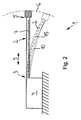
- a remote from the attachment point 3 free end portion 5 of the bending beam 2 is from a neutral position, in which the bending beam 2 in one of the plane in Fig. 1 corresponding plane is arranged, approximately at right angles to this plane against the restoring force of the material of the bending beam 2 elastically deflectable. As in Fig. 2 can be seen, thereby moving the end portion 5 of the bending beam 2 along a curved trajectory. 6
- an electromechanical transducer element 7 is integrated in the bending beam.
- a first piezoelectric element is provided, which is arranged in a near-surface layer of the bending beam 2 and is axially stretched or compressed in a bending deformation of the bending beam 2. Due to charge shifts in the piezoelectric element occurs in the drawing, not shown electrodes of the piezoelectric element on an electrical voltage that feeds an electrical load 8.
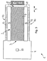
- the free end region 5 of the bending beam 2 is connected to the holder 4 via two bridge parts 10 arranged outside the bending beam 2.
- the bridge parts 10 extend in neutral position located bending beam 2 on both sides of the bending beam 2 approximately parallel to this and are each spaced by a slot-shaped clearance transverse to the longitudinal direction 9 of the bending beam 2 of this. In neutral position of the bending beam 2, the bridge parts 10 and the bending beam 2 are arranged in the same plane.
- each bridge portion 10 is connected via a cross-connecting piece 11 with the free end portion 5 of the bending beam 2.
- the cross-connecting piece 11 extends in the neutral position located bending beam 2 in the plane in which the bending beam 2 is arranged, transversely to the longitudinal direction 9 of the bending beam. 2
- the holder 4, the bending beam 2, the bridge parts 10 and the cross connectors 11 are integrally connected to each other.
- they can be made of plastic.
- the bridge parts 10 are each laterally spaced from the bending beam 2 by a slot-shaped free space 12 running approximately parallel to the bending beam 2.
- an adjusting device For applying a substantially in the longitudinal direction 11 of the bridge parts 10 oriented mechanical bias on the bending beam 2, an adjusting device is provided which has a second piezoelectric element for each bridge part 10 each as an actuator 1 3.
- the actuator 13 is in each case integrated into the bridge part 10.
- the actuator 1 3 extends only over a portion of the bridge part 10 Fig. 3
- the axial length of the bridge portion 10 can be shortened and / or increased by the actuator 1 3 by means of a control device 14, an electric Voltage is applied. If the length of the bridge part 10 is shortened, the resonance frequency of the oscillatory system formed by the bending beam 2 and the bridge part 10 decreases. If the length of the bridge part 10 is increased, the resonant frequency of the oscillatory system increases.
- Fig. 2 It can be seen that the bending beam 2 extends along a curved bending line 15 when it is deflected from the neutral position, and that the line along which extends the bridge portion 10, deviates from the bending line of the bending beam 2 with existing bias.
- the line along which the bridge part 10 extends has a different geometry than the bending line 15 and is shorter than this.
- the bridge part 10 is connected to a first pivot joint 16 spaced from the free end region 5 of the bending beam 2 via a first pivot joint with the support 4 and a second joint 17 provided at the free end region 5 of the bending beam 2 Swivel joint pivotally connected to the bending beam 2 and the cross-connecting piece 11.
- the pivot joints are preferably configured as solid-state joints whose pivot axes extend normal to the plane in which the trajectory 6 extends.
- the transducer element 7 of the bending beam 2 has on both sides of a middle layer a piezoelectric layer which is used to generate electrical energy.
- a middle layer a piezoelectric layer which is used to generate electrical energy.
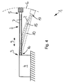
- the bending beam 2 and the two bridge parts 10 are arranged in neutral position in mutually parallel planes. Between the bridge part 10 and the bending beam 2 is in each case an approximately parallel to the bending beam 2 extending slot-shaped movement clearance 21 is provided.
- the bridge parts 10 are arranged mirror-symmetrically to the longitudinal center axis of the bending beam 2.
- a piezoelectric actuator 1 3 between the frontal free end of the bending beam 2 and the cross-connecting pieces 11 is arranged. This makes it possible to change the maximum length of the bending beam 2 in relation to the axial length of the bridge parts 10 and thus exert an axial bias on the bending beam 2.
- the actuator 1 3 acts as a seismic mass.
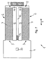
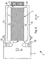
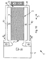
- the energy converter 1 has two mutually parallel, one-sided clamped to the bracket 2 bending beam 2, between which a likewise clamped on one side of the bracket 2 bridge part 10 is arranged.
- the bridge parts 10 and the bending beam 2 extend in the same plane.
- the bending beam 2 is laterally on both sides in each case by a slot-shaped, approximately parallel to the bending beam 2 extending free space 12 of the relevant Bridge part 10 spaced. It can clearly be seen that the bending beams 2 are arranged mirror-symmetrically to the longitudinal central axis of the bridge part 10.
- bending beam 2 and the bridge part 10 can also be arranged asymmetrically to each other.
- energy converter 1 are on the holder 4 two approximately at right angles to the longitudinal extension 9 of the bending beam 2 in opposite directions facing arms 1 8 formed, which are arranged in the plane in which the bending beam 2 extends in neutral position.
- Each arm 1 8 each has an arm portion which is deflectable in the longitudinal extension 9 of the bending beam 2 relative to the holder 4.
- a free space 12 is formed on the side facing away from the bridge parts 1 0 side of the arms 1 8, in which a piezoelectric element is arranged as an actuator 13.
- the actuator 1 3 is supported in each case with its one end against the deflectable arm portion and with its other end against an abutment point of the holder 4.
- the deflectable arm portions are each connected to the remote from the free end portion 5 end of the respective arm 1 8 associated bridge member 10. With the help of the actuators 13, the arms 18 can be adjusted in the direction of the double arrows 19.
- the actuators 1 3 may also be connected via a freestanding structure with the bridge parts 10.
- control device 14 has a measuring signal input to which a control signal dependent on the frequency of the mechanical excitation oscillation is applied.
- the control signal is detected by means of a sensor 20 arranged on the holder 4.
- the at least one actuator 1 3 is so in control connection with the control device 14, that the force exerted on the bending beam 2 mechanical bias depending on the frequency of the mechanical vibration is set so that in the conversion of mechanical vibrations in the electrical energy as possible high efficiency is achieved.
- the control device 14 and a connected to the transducer element 7 electrical load 14 are arranged on the bending beam 2 at a distance from the supply point 3 and serve as a seismic mass.
- a control circuit may be provided which is configured such that the actuator 1 3 each driven so that the energy converter 1 is operated at an operating point, where he gives his maximum performance.
Landscapes
- General Electrical Machinery Utilizing Piezoelectricity, Electrostriction Or Magnetostriction (AREA)
Claims (14)
- Convertisseur d'énergie électromécanique (1) pour générer de l'énergie électrique à partir de mouvements mécaniques, comprenant au moins une tige flexible (2) qui est enserrée en un point de fixation (3) sur un support (4) pouvant être mis en mouvement et comprenant une zone d'extrémité libre (5) éloignée du point de fixation (5) qui peut être déviée depuis une position neutre transversalement par rapport à la projection longitudinale (9) de la tige flexible (2) par rapport au point de fixation (3) le long d'une portion de trajectoire (6), un point pouvant être dévié de la tige flexible (2) étant relié avec le support (4) pour appliquer sur la tige flexible (2) une précontrainte mécanique orientée pour l'essentiel dans le sens de la projection longitudinale (9) de la tige flexible (2) par le biais d'au moins une pièce faisant pont (10) pouvant être déviée qui s'étend le long de la tige flexible (2), comprenant un dispositif de réglage pour régler la précontrainte transmise de la pièce faisant pont (10) à la tige flexible (2), et comprenant au moins un élément convertisseur électromécanique (7) qui se trouve en liaison motrice avec la tige flexible (2) en vue de convertir l'énergie de mouvement mécanique en énergie électrique, caractérisé en ce que la pièce faisant pont (10) est disposée à l'extérieur de la tige flexible (2) de telle sorte que la tige flexible (2) et la pièce faisant pont (10), au moins lorsque la tige flexible (2) est déviée de la position neutre et en présence de la précontrainte, s'étendent le long de lignes qui présentent des tracés différents.
- Convertisseur d'énergie électromécanique (1) selon la revendication 1, caractérisé en ce que la pièce faisant pont (10) est enserrée sur le support (4) et de préférence flexible avec effet élastique.
- Convertisseur d'énergie électromécanique (1) selon 1a revendication 1 ou 2, caractérisé en ce que la pièce faisant pont (10) est reliée avec le support (4) en un premier point d'articulation (16) espacé du point pouvant être dévié de la tige flexible (2) par le biais d'une première articulation de pivotement et/ou de manière pivotante avec la tige flexible (2) en un deuxième point d'articulation (17) disposé en un point espacé du point de fixation (3) par le biais d'une deuxième articulation de pivotement, et en ce qu'un axe de pivotement de la première articulation de pivotement et/ou un axe de pivotement de la deuxième articulation de pivotement s'étendent de préférence dans la direction normale par rapport au plan dans lequel s'étend la portion de trajectoire (6) et le long duquel peut être déviée la zone d'extrémité libre (5) de la tige flexible (2).
- Convertisseur d'énergie électromécanique (1) selon l'une des revendications 1 à 3, caractérisé en ce que dans la position neutre de la tige flexible (2), la tige flexible (2) et l'au moins une pièce faisant pont (10) s'étendent dans le même plan et sont décalées latéralement l'une par rapport à l'autre dans la direction normale par rapport à la projection longitudinale (9) de la tige flexible (2).
- Convertisseur d'énergie électromécanique (1) selon l'une des revendications 1 à 4, caractérisé en ce que l'au moins une pièce faisant pont (10), transversalement par rapport à la projection longitudinale (9) de la tige flexible (2), est espacée par un espace libre (12) de préférence en forme de fente qui s'étend le long de la tige flexible (2), et en ce que la pièce faisant pont (10) est reliée avec le point pouvant être dévié de la tige flexible (2) par le biais d'une pièce de liaison transversale (11) au niveau de son extrémité éloignée du support (4).
- Convertisseur d'énergie électromécanique (1) selon l'une des revendications 1 à 5, caractérisé en ce que la tige flexible (2) et l'au moins une pièce faisant pont (10), en position neutre, sont disposées dans des plans décalés l'un de l'autre s'étendant en parallèle l'un à l'autre en direction de la portion de trajectoire (6) le long de laquelle peut être déviée la zone d'extrémité libre de la tige flexible (2) et sont espacées l'une de l'autre par un espace libre de mouvement (21) en direction de la portion de trajectoire (6).
- Convertisseur d'énergie électromécanique (1) selon l'une des revendications 1 à 6, caractérisé en ce que l'au moins un élément convertisseur (7) est un élément piézoélectrique qui est intégré dans la tige flexible (2) et est de préférence disposé dans une couche proche de la surface de la tige flexible (7).
- Convertisseur d'énergie électromécanique (1) selon l'une des revendications 1 à 7, caractérisé en ce que le dispositif de réglage présente comme élément de réglage (13) au moins un élément piézoélectrique qui est disposé entre la pièce faisant pont (10) et le support (4) et/ou entre la pièce faisant pont (10) et la tige flexible (2) et/ou intégré dans la pièce faisant pont (10).
- Convertisseur d'énergie électromécanique (1) selon l'une des revendications 1 à 8, caractérisé en ce qu'au moins un bras (18) qui s'étend transversalement par rapport à la projection longitudinale (9) de la tige flexible (2) est formé sur le support (4), lequel présente une portion de bras qui peut être déviée par rapport au support (4) dans la projection longitudinale (9) de la tige flexible (2), en ce que cette portion de bras est reliée par le biais de la pièce faisant pont (10) avec le point pouvant être dévié de la tige flexible (2) et en ce que l'élément de réglage (13) est disposé entre la portion de bras et un point d'aboutement prévu sur le support (4).
- Convertisseur d'énergie électromécanique (1) selon l'une des revendications 1 à 9, caractérisé en ce qu'il présente au moins deux pièces faisant pont (10) et en ce que la tige flexible (2) est disposée de manière symétrique entre ces pièces faisant pont (10).
- Convertisseur d'énergie électromécanique (1) selon l'une des revendications 1 à 10, caractérisé en ce qu'il présente au moins deux tiges flexibles (2) et en ce que la pièce faisant pont (10) est disposée de manière symétrique entre ces tiges flexibles (2).
- Convertisseur d'énergie électromécanique (1) selon l'une des revendications 1 à 11, caractérisé en ce qu'il présente un dispositif de commande (14) muni d'une entrée pour un signal de commande dépendant de la fréquence d'une oscillation mécanique du support (4), et en ce que le dispositif de commande (14) se trouve en liaison de commande avec le dispositif de réglage de telle sorte que la précontrainte peut être réglée en fonction de la fréquence de l'oscillation mécanique.
- Convertisseur d'énergie électromécanique (1) selon l'une des revendications 1 à 12, caractérisé en ce que le dispositif de commande (14) et/ou un accumulateur d'énergie en liaison électrique avec l'élément convertisseur (7) et/ou une charge électrique (8) raccordée à l'élément convertisseur (7) sont disposés sur la tige flexible (2) à une certaine distance du point de fixation (3), de préférence à la zone d'extrémité libre (5) de la tige flexible (2).
- Convertisseur d'énergie électromécanique (1) selon l'une des revendications 1 à 13, caractérisé en ce qu'il présente un dispositif de mesure pour détecter une modification de la puissance électrique délivrée par l'élément convertisseur (7) et des moyens pour détecter une modification de la fréquence de l'oscillation mécanique de la tige flexible (2), et en ce que le dispositif de mesure et les moyens pour détecter une modification de la fréquence interagissent avec le dispositif de réglage par le biais d'un circuit de régulation de telle sorte- qu'en cas de diminution simultanée de la fréquence eL de la puissance, l'élément de réglage (13) du dispositif de réglage est ajusté dans le sens d'une réduction de la fréquence de résonance de la tige flexible (2) et/ou- qu'en cas d' augmentation de la fréquence et d' une diminution simultanée de la puissance, l'élément de réglage (13) du dispositif de réglage est ajusté dans le sens d'une augmentation de la fréquence de résonance de la tige flexible (2).
Applications Claiming Priority (2)
| Application Number | Priority Date | Filing Date | Title |
|---|---|---|---|
| DE102008056127A DE102008056127A1 (de) | 2008-11-06 | 2008-11-06 | Elektromechanischer Energiewandler zur Erzeugung von elektrischer Energie aus mechanischen Bewegungen |
| PCT/EP2009/007959 WO2010052009A1 (fr) | 2008-11-06 | 2009-11-06 | Convertisseur d'énergie électromécanique destiné à produire de l'énergie électrique à partir de mouvements mécaniques |
Publications (2)
| Publication Number | Publication Date |
|---|---|
| EP2361443A1 EP2361443A1 (fr) | 2011-08-31 |
| EP2361443B1 true EP2361443B1 (fr) | 2013-01-16 |
Family
ID=41716407
Family Applications (1)
| Application Number | Title | Priority Date | Filing Date |
|---|---|---|---|
| EP09756426A Not-in-force EP2361443B1 (fr) | 2008-11-06 | 2009-11-06 | Convertisseur d'énergie électromécanique destiné à produire de l'énergie électrique à partir de mouvements mécaniques |
Country Status (4)
| Country | Link |
|---|---|
| US (1) | US8664834B2 (fr) |
| EP (1) | EP2361443B1 (fr) |
| DE (1) | DE102008056127A1 (fr) |
| WO (1) | WO2010052009A1 (fr) |
Families Citing this family (10)
| Publication number | Priority date | Publication date | Assignee | Title |
|---|---|---|---|---|
| EP2302712A1 (fr) * | 2009-09-28 | 2011-03-30 | Stichting IMEC Nederland | Procédé de réglage de fréquence à résonance de structures micro-usinées |
| FI123941B (fi) | 2010-09-07 | 2013-12-31 | Murata Electronics Oy | Energiankerääjärakenne ja -menetelmä |
| EP2610935A1 (fr) * | 2012-01-02 | 2013-07-03 | Stichting IMEC Nederland | Dispositif d'exploitation d'énergie |
| US8456028B1 (en) | 2012-02-06 | 2013-06-04 | Elwha Llc | Method and apparatus for storing energy |
| US8581446B2 (en) | 2012-02-06 | 2013-11-12 | Elwha Llc | Method and apparatus for removal of harmonic noise |
| EP3295554B1 (fr) | 2015-05-11 | 2019-04-24 | Yeditepe Universitesi | Dispositif de collecte d'énergie de vibration |
| DE102017212635A1 (de) | 2017-07-24 | 2019-01-24 | Robert Bosch Gmbh | Energiewandlungssystem, Verfahren zur Herstellung eines Energiewandlungssystems, energieautarker Sensor, Verfahren zur Herstellung eines energieautarken Sensors und drahtloses Sensornetz |
| DE102017212636A1 (de) | 2017-07-24 | 2019-01-24 | Robert Bosch Gmbh | Energiewandlungssystem, Verfahren zur Herstellung eines Energiewandlungssystems, energieautarker Sensor, Verfahren zur Herstellung eines energieautarken Sensors und drahtloses Sensornetz |
| GB2586067B (en) | 2019-08-01 | 2021-10-27 | Katrick Tech Limited | Energy harvesting system and method of manufacture |
| CN116482423B (zh) * | 2023-05-09 | 2024-06-04 | 深圳市三行技术有限公司 | 一种中压变频驱动器的采样电路异常检测设备 |
Family Cites Families (13)
| Publication number | Priority date | Publication date | Assignee | Title |
|---|---|---|---|---|
| US3058539A (en) * | 1958-05-15 | 1962-10-16 | Zenith Radio Corp | Transducer with impedance-matching bridge |
| DE19750187C2 (de) * | 1997-11-13 | 2000-06-29 | Bosch Gmbh Robert | Ultraschallmotor |
| DE10259069B4 (de) | 2002-12-17 | 2007-01-25 | Patent-Treuhand-Gesellschaft für elektrische Glühlampen mbH | Resonanzkonverter und Verfahren zum Treiben von veränderlichen Lasten |
| DE10259088B4 (de) | 2002-12-17 | 2007-01-25 | Infineon Technologies Ag | Resonanzkonverter mit Spannungsregelung und Verfahren zum Treiben von veränderlichen Lasten |
| EP1654771B1 (fr) * | 2003-07-30 | 2010-03-10 | The Boeing Company | Appareil de navette a energie de deformation et procede de recueil d'energie de vibration |
| US7737608B2 (en) * | 2003-07-30 | 2010-06-15 | The Boeing Company | Enhanced amplitude piezoelectric motor apparatus and method |
| US7960900B2 (en) * | 2004-06-14 | 2011-06-14 | Stmicroelectronics S.A. | Assembly of a microswitch and of an acoustic resonator |
| US7692365B2 (en) * | 2005-11-23 | 2010-04-06 | Microstrain, Inc. | Slotted beam piezoelectric composite |
| US7687977B2 (en) * | 2006-04-10 | 2010-03-30 | Honeywell International Inc. | Micromachined, piezoelectric vibration-induced energy harvesting device and its fabrication |
| US7439657B2 (en) * | 2006-10-20 | 2008-10-21 | The Boeing Company | Broadband energy harvester apparatus and method |
| US7839058B1 (en) * | 2007-01-29 | 2010-11-23 | Microstrain, Inc. | Wideband vibration energy harvester |
| US9048419B2 (en) | 2007-05-31 | 2015-06-02 | Wayne State University | Piezo devices with air-spaced cantilever |
| US7928634B2 (en) * | 2008-04-22 | 2011-04-19 | Honeywell International Inc. | System and method for providing a piezoelectric electromagnetic hybrid vibrating energy harvester |
-
2008
- 2008-11-06 DE DE102008056127A patent/DE102008056127A1/de not_active Withdrawn
-
2009
- 2009-11-06 US US13/127,778 patent/US8664834B2/en not_active Expired - Fee Related
- 2009-11-06 WO PCT/EP2009/007959 patent/WO2010052009A1/fr not_active Ceased
- 2009-11-06 EP EP09756426A patent/EP2361443B1/fr not_active Not-in-force
Also Published As
| Publication number | Publication date |
|---|---|
| DE102008056127A1 (de) | 2010-06-10 |
| EP2361443A1 (fr) | 2011-08-31 |
| US8664834B2 (en) | 2014-03-04 |
| US20110304239A1 (en) | 2011-12-15 |
| WO2010052009A1 (fr) | 2010-05-14 |
Similar Documents
| Publication | Publication Date | Title |
|---|---|---|
| EP2361443B1 (fr) | Convertisseur d'énergie électromécanique destiné à produire de l'énergie électrique à partir de mouvements mécaniques | |
| DE19739877C2 (de) | Mechanischer Resonator mit variabler Resonanzfrequenz | |
| DE102013107154B4 (de) | Antriebsvorrichtung | |
| DE102004024656A1 (de) | Piezoelektrischer Ultraschallmotor | |
| EP1927782A1 (fr) | Amortisseur à masse syntonisée actif | |
| WO2009124607A1 (fr) | Structure d'actionnement micromécanique et procédé d'actionnement correspondant | |
| EP2316161B1 (fr) | Procédé et dispositif pour produire de l'énergie électrique à partir d'une vibration d'excitation mécanique | |
| DE102008053646A1 (de) | Linearantrieb mit Schockkompensation | |
| EP1882112B1 (fr) | Dispositif de decouplage d'oscillations | |
| DE102004030935B3 (de) | Vorrichtung zur Schwingungsdämpfung in einem Kraftfahrzeug | |
| DE102007052494A1 (de) | Piezoelektrische Antriebsvorrichtung | |
| DE102004046150A1 (de) | Vorrichtung und Verfahren zur Schwingungsbeeinflussung eines Flächenelementes | |
| EP0816868A2 (fr) | Emetteur laser avec un faisceau explorateur tournant | |
| DE3038660A1 (de) | Beschleunigungsaufnehmer mit piezoelektrischem wandlerelement | |
| EP3301730B1 (fr) | Convertisseur d'énergie | |
| DE102005016038B3 (de) | Verfahren zur zyklischen Scherbelastungsprüfung von Mikroverbindungen zwischen Werkstoffen | |
| EP1938397B1 (fr) | Moteur lineaire a ultrasons | |
| EP2316158B1 (fr) | Résonateur mécanique | |
| DE102008043229B4 (de) | Aktuatorvorrichtung | |
| EP4300267B1 (fr) | Dispositif d'entrée avec des éléments de ressort améliorés pour le montage mobile de la partie de commande, élément de ressort correspondant ainsi que procédé de montage | |
| DE102011088331A1 (de) | Mikromechanische Struktur und mikromechanisches Sensorelement | |
| EP1500183A2 (fr) | Piezomoteur | |
| DE102004007444A1 (de) | Schaberdämpfung | |
| EP2150994B1 (fr) | Actionneur flexible à corps solide comportant un élément d'allongement | |
| DE102007021336A1 (de) | Piezoelektrische Antriebsvorrichtung |
Legal Events
| Date | Code | Title | Description |
|---|---|---|---|
| PUAI | Public reference made under article 153(3) epc to a published international application that has entered the european phase |
Free format text: ORIGINAL CODE: 0009012 |
|
| 17P | Request for examination filed |
Effective date: 20110517 |
|
| AK | Designated contracting states |
Kind code of ref document: A1 Designated state(s): AT BE BG CH CY CZ DE DK EE ES FI FR GB GR HR HU IE IS IT LI LT LU LV MC MK MT NL NO PL PT RO SE SI SK SM TR |
|
| DAX | Request for extension of the european patent (deleted) | ||
| REG | Reference to a national code |
Ref country code: DE Ref legal event code: R079 Ref document number: 502009006058 Country of ref document: DE Free format text: PREVIOUS MAIN CLASS: H01L0041113000 Ipc: H02N0002180000 |
|
| GRAP | Despatch of communication of intention to grant a patent |
Free format text: ORIGINAL CODE: EPIDOSNIGR1 |
|
| RIC1 | Information provided on ipc code assigned before grant |
Ipc: H02N 2/18 20060101AFI20120808BHEP Ipc: H01L 41/113 20060101ALI20120808BHEP |
|
| GRAS | Grant fee paid |
Free format text: ORIGINAL CODE: EPIDOSNIGR3 |
|
| GRAA | (expected) grant |
Free format text: ORIGINAL CODE: 0009210 |
|
| AK | Designated contracting states |
Kind code of ref document: B1 Designated state(s): AT BE BG CH CY CZ DE DK EE ES FI FR GB GR HR HU IE IS IT LI LT LU LV MC MK MT NL NO PL PT RO SE SI SK SM TR |
|
| REG | Reference to a national code |
Ref country code: GB Ref legal event code: FG4D Free format text: NOT ENGLISH |
|
| REG | Reference to a national code |
Ref country code: CH Ref legal event code: EP |
|
| REG | Reference to a national code |
Ref country code: IE Ref legal event code: FG4D Free format text: LANGUAGE OF EP DOCUMENT: GERMAN |
|
| REG | Reference to a national code |
Ref country code: CH Ref legal event code: EP Ref country code: AT Ref legal event code: REF Ref document number: 594347 Country of ref document: AT Kind code of ref document: T Effective date: 20130215 |
|
| REG | Reference to a national code |
Ref country code: DE Ref legal event code: R096 Ref document number: 502009006058 Country of ref document: DE Effective date: 20130314 |
|
| REG | Reference to a national code |
Ref country code: NL Ref legal event code: VDEP Effective date: 20130116 |
|
| REG | Reference to a national code |
Ref country code: LT Ref legal event code: MG4D |
|
| PG25 | Lapsed in a contracting state [announced via postgrant information from national office to epo] |
Ref country code: BG Free format text: LAPSE BECAUSE OF FAILURE TO SUBMIT A TRANSLATION OF THE DESCRIPTION OR TO PAY THE FEE WITHIN THE PRESCRIBED TIME-LIMIT Effective date: 20130416 Ref country code: SE Free format text: LAPSE BECAUSE OF FAILURE TO SUBMIT A TRANSLATION OF THE DESCRIPTION OR TO PAY THE FEE WITHIN THE PRESCRIBED TIME-LIMIT Effective date: 20130116 Ref country code: IS Free format text: LAPSE BECAUSE OF FAILURE TO SUBMIT A TRANSLATION OF THE DESCRIPTION OR TO PAY THE FEE WITHIN THE PRESCRIBED TIME-LIMIT Effective date: 20130516 Ref country code: LT Free format text: LAPSE BECAUSE OF FAILURE TO SUBMIT A TRANSLATION OF THE DESCRIPTION OR TO PAY THE FEE WITHIN THE PRESCRIBED TIME-LIMIT Effective date: 20130116 Ref country code: ES Free format text: LAPSE BECAUSE OF FAILURE TO SUBMIT A TRANSLATION OF THE DESCRIPTION OR TO PAY THE FEE WITHIN THE PRESCRIBED TIME-LIMIT Effective date: 20130427 Ref country code: NO Free format text: LAPSE BECAUSE OF FAILURE TO SUBMIT A TRANSLATION OF THE DESCRIPTION OR TO PAY THE FEE WITHIN THE PRESCRIBED TIME-LIMIT Effective date: 20130416 |
|
| PG25 | Lapsed in a contracting state [announced via postgrant information from national office to epo] |
Ref country code: NL Free format text: LAPSE BECAUSE OF FAILURE TO SUBMIT A TRANSLATION OF THE DESCRIPTION OR TO PAY THE FEE WITHIN THE PRESCRIBED TIME-LIMIT Effective date: 20130116 Ref country code: LV Free format text: LAPSE BECAUSE OF FAILURE TO SUBMIT A TRANSLATION OF THE DESCRIPTION OR TO PAY THE FEE WITHIN THE PRESCRIBED TIME-LIMIT Effective date: 20130116 Ref country code: PL Free format text: LAPSE BECAUSE OF FAILURE TO SUBMIT A TRANSLATION OF THE DESCRIPTION OR TO PAY THE FEE WITHIN THE PRESCRIBED TIME-LIMIT Effective date: 20130116 Ref country code: SI Free format text: LAPSE BECAUSE OF FAILURE TO SUBMIT A TRANSLATION OF THE DESCRIPTION OR TO PAY THE FEE WITHIN THE PRESCRIBED TIME-LIMIT Effective date: 20130116 Ref country code: PT Free format text: LAPSE BECAUSE OF FAILURE TO SUBMIT A TRANSLATION OF THE DESCRIPTION OR TO PAY THE FEE WITHIN THE PRESCRIBED TIME-LIMIT Effective date: 20130516 Ref country code: GR Free format text: LAPSE BECAUSE OF FAILURE TO SUBMIT A TRANSLATION OF THE DESCRIPTION OR TO PAY THE FEE WITHIN THE PRESCRIBED TIME-LIMIT Effective date: 20130417 Ref country code: FI Free format text: LAPSE BECAUSE OF FAILURE TO SUBMIT A TRANSLATION OF THE DESCRIPTION OR TO PAY THE FEE WITHIN THE PRESCRIBED TIME-LIMIT Effective date: 20130116 |
|
| PG25 | Lapsed in a contracting state [announced via postgrant information from national office to epo] |
Ref country code: HR Free format text: LAPSE BECAUSE OF FAILURE TO SUBMIT A TRANSLATION OF THE DESCRIPTION OR TO PAY THE FEE WITHIN THE PRESCRIBED TIME-LIMIT Effective date: 20130116 |
|
| PG25 | Lapsed in a contracting state [announced via postgrant information from national office to epo] |
Ref country code: RO Free format text: LAPSE BECAUSE OF FAILURE TO SUBMIT A TRANSLATION OF THE DESCRIPTION OR TO PAY THE FEE WITHIN THE PRESCRIBED TIME-LIMIT Effective date: 20130116 Ref country code: EE Free format text: LAPSE BECAUSE OF FAILURE TO SUBMIT A TRANSLATION OF THE DESCRIPTION OR TO PAY THE FEE WITHIN THE PRESCRIBED TIME-LIMIT Effective date: 20130116 Ref country code: SK Free format text: LAPSE BECAUSE OF FAILURE TO SUBMIT A TRANSLATION OF THE DESCRIPTION OR TO PAY THE FEE WITHIN THE PRESCRIBED TIME-LIMIT Effective date: 20130116 Ref country code: DK Free format text: LAPSE BECAUSE OF FAILURE TO SUBMIT A TRANSLATION OF THE DESCRIPTION OR TO PAY THE FEE WITHIN THE PRESCRIBED TIME-LIMIT Effective date: 20130116 Ref country code: CZ Free format text: LAPSE BECAUSE OF FAILURE TO SUBMIT A TRANSLATION OF THE DESCRIPTION OR TO PAY THE FEE WITHIN THE PRESCRIBED TIME-LIMIT Effective date: 20130116 |
|
| PLBE | No opposition filed within time limit |
Free format text: ORIGINAL CODE: 0009261 |
|
| STAA | Information on the status of an ep patent application or granted ep patent |
Free format text: STATUS: NO OPPOSITION FILED WITHIN TIME LIMIT |
|
| PG25 | Lapsed in a contracting state [announced via postgrant information from national office to epo] |
Ref country code: CY Free format text: LAPSE BECAUSE OF FAILURE TO SUBMIT A TRANSLATION OF THE DESCRIPTION OR TO PAY THE FEE WITHIN THE PRESCRIBED TIME-LIMIT Effective date: 20130116 |
|
| REG | Reference to a national code |
Ref country code: DE Ref legal event code: R082 Ref document number: 502009006058 Country of ref document: DE Representative=s name: HUWER, ANDREAS, DIPL.-ING. DR.-ING., DE |
|
| 26N | No opposition filed |
Effective date: 20131017 |
|
| REG | Reference to a national code |
Ref country code: DE Ref legal event code: R082 Ref document number: 502009006058 Country of ref document: DE Representative=s name: HUWER, ANDREAS, DIPL.-ING. DR.-ING., DE Effective date: 20131204 Ref country code: DE Ref legal event code: R081 Ref document number: 502009006058 Country of ref document: DE Owner name: ALBERT-LUDWIGS-UNIVERSITAET FREIBURG, DE Free format text: FORMER OWNER: ALBERT-LUDWIGS-UNIVERSITAET FREIBURG, 79104 FREIBURG, DE Effective date: 20131204 |
|
| REG | Reference to a national code |
Ref country code: DE Ref legal event code: R097 Ref document number: 502009006058 Country of ref document: DE Effective date: 20131017 |
|
| BERE | Be: lapsed |
Owner name: ALBERT-LUDWIGS-UNIVERSITAT FREIBURG Effective date: 20131130 |
|
| REG | Reference to a national code |
Ref country code: CH Ref legal event code: PL |
|
| PG25 | Lapsed in a contracting state [announced via postgrant information from national office to epo] |
Ref country code: LI Free format text: LAPSE BECAUSE OF NON-PAYMENT OF DUE FEES Effective date: 20131130 Ref country code: MC Free format text: LAPSE BECAUSE OF FAILURE TO SUBMIT A TRANSLATION OF THE DESCRIPTION OR TO PAY THE FEE WITHIN THE PRESCRIBED TIME-LIMIT Effective date: 20130116 Ref country code: CH Free format text: LAPSE BECAUSE OF NON-PAYMENT OF DUE FEES Effective date: 20131130 |
|
| REG | Reference to a national code |
Ref country code: IE Ref legal event code: MM4A |
|
| PG25 | Lapsed in a contracting state [announced via postgrant information from national office to epo] |
Ref country code: BE Free format text: LAPSE BECAUSE OF NON-PAYMENT OF DUE FEES Effective date: 20131130 |
|
| PG25 | Lapsed in a contracting state [announced via postgrant information from national office to epo] |
Ref country code: IE Free format text: LAPSE BECAUSE OF NON-PAYMENT OF DUE FEES Effective date: 20131106 |
|
| PG25 | Lapsed in a contracting state [announced via postgrant information from national office to epo] |
Ref country code: SM Free format text: LAPSE BECAUSE OF FAILURE TO SUBMIT A TRANSLATION OF THE DESCRIPTION OR TO PAY THE FEE WITHIN THE PRESCRIBED TIME-LIMIT Effective date: 20130116 |
|
| PG25 | Lapsed in a contracting state [announced via postgrant information from national office to epo] |
Ref country code: TR Free format text: LAPSE BECAUSE OF FAILURE TO SUBMIT A TRANSLATION OF THE DESCRIPTION OR TO PAY THE FEE WITHIN THE PRESCRIBED TIME-LIMIT Effective date: 20130116 |
|
| PG25 | Lapsed in a contracting state [announced via postgrant information from national office to epo] |
Ref country code: LU Free format text: LAPSE BECAUSE OF NON-PAYMENT OF DUE FEES Effective date: 20131106 Ref country code: MK Free format text: LAPSE BECAUSE OF FAILURE TO SUBMIT A TRANSLATION OF THE DESCRIPTION OR TO PAY THE FEE WITHIN THE PRESCRIBED TIME-LIMIT Effective date: 20130116 Ref country code: HU Free format text: LAPSE BECAUSE OF FAILURE TO SUBMIT A TRANSLATION OF THE DESCRIPTION OR TO PAY THE FEE WITHIN THE PRESCRIBED TIME-LIMIT; INVALID AB INITIO Effective date: 20091106 |
|
| PG25 | Lapsed in a contracting state [announced via postgrant information from national office to epo] |
Ref country code: MT Free format text: LAPSE BECAUSE OF FAILURE TO SUBMIT A TRANSLATION OF THE DESCRIPTION OR TO PAY THE FEE WITHIN THE PRESCRIBED TIME-LIMIT Effective date: 20130116 |
|
| REG | Reference to a national code |
Ref country code: FR Ref legal event code: PLFP Year of fee payment: 7 |
|
| REG | Reference to a national code |
Ref country code: AT Ref legal event code: MM01 Ref document number: 594347 Country of ref document: AT Kind code of ref document: T Effective date: 20141106 |
|
| PG25 | Lapsed in a contracting state [announced via postgrant information from national office to epo] |
Ref country code: AT Free format text: LAPSE BECAUSE OF NON-PAYMENT OF DUE FEES Effective date: 20141106 |
|
| REG | Reference to a national code |
Ref country code: FR Ref legal event code: PLFP Year of fee payment: 8 |
|
| REG | Reference to a national code |
Ref country code: FR Ref legal event code: PLFP Year of fee payment: 9 |
|
| REG | Reference to a national code |
Ref country code: DE Ref legal event code: R082 Ref document number: 502009006058 Country of ref document: DE |
|
| PGFP | Annual fee paid to national office [announced via postgrant information from national office to epo] |
Ref country code: GB Payment date: 20231123 Year of fee payment: 15 |
|
| PGFP | Annual fee paid to national office [announced via postgrant information from national office to epo] |
Ref country code: IT Payment date: 20231130 Year of fee payment: 15 Ref country code: FR Payment date: 20231124 Year of fee payment: 15 Ref country code: DE Payment date: 20231120 Year of fee payment: 15 |
|
| REG | Reference to a national code |
Ref country code: DE Ref legal event code: R119 Ref document number: 502009006058 Country of ref document: DE |
|
| GBPC | Gb: european patent ceased through non-payment of renewal fee |
Effective date: 20241106 |
|
| PG25 | Lapsed in a contracting state [announced via postgrant information from national office to epo] |
Ref country code: DE Free format text: LAPSE BECAUSE OF NON-PAYMENT OF DUE FEES Effective date: 20250603 |
|
| PG25 | Lapsed in a contracting state [announced via postgrant information from national office to epo] |
Ref country code: IT Free format text: LAPSE BECAUSE OF NON-PAYMENT OF DUE FEES Effective date: 20241106 |
|
| PG25 | Lapsed in a contracting state [announced via postgrant information from national office to epo] |
Ref country code: GB Free format text: LAPSE BECAUSE OF NON-PAYMENT OF DUE FEES Effective date: 20241106 |
|
| PG25 | Lapsed in a contracting state [announced via postgrant information from national office to epo] |
Ref country code: FR Free format text: LAPSE BECAUSE OF NON-PAYMENT OF DUE FEES Effective date: 20241130 |