EP2362045A2 - Porte pour une armoire électrique - Google Patents
Porte pour une armoire électrique Download PDFInfo
- Publication number
- EP2362045A2 EP2362045A2 EP11001294A EP11001294A EP2362045A2 EP 2362045 A2 EP2362045 A2 EP 2362045A2 EP 11001294 A EP11001294 A EP 11001294A EP 11001294 A EP11001294 A EP 11001294A EP 2362045 A2 EP2362045 A2 EP 2362045A2
- Authority
- EP
- European Patent Office
- Prior art keywords
- hinge
- door
- hinge body
- pin
- fold
- Prior art date
- Legal status (The legal status is an assumption and is not a legal conclusion. Google has not performed a legal analysis and makes no representation as to the accuracy of the status listed.)
- Granted
Links
Images



Classifications
-
- E—FIXED CONSTRUCTIONS
- E05—LOCKS; KEYS; WINDOW OR DOOR FITTINGS; SAFES
- E05D—HINGES OR SUSPENSION DEVICES FOR DOORS, WINDOWS OR WINGS
- E05D7/00—Hinges or pivots of special construction
- E05D7/10—Hinges or pivots of special construction to allow easy separation or connection of the parts at the hinge axis
- E05D7/1005—Hinges or pivots of special construction to allow easy separation or connection of the parts at the hinge axis by axially moving free pins, balls or sockets
-
- E—FIXED CONSTRUCTIONS
- E05—LOCKS; KEYS; WINDOW OR DOOR FITTINGS; SAFES
- E05D—HINGES OR SUSPENSION DEVICES FOR DOORS, WINDOWS OR WINGS
- E05D7/00—Hinges or pivots of special construction
- E05D7/04—Hinges adjustable relative to the wing or the frame
-
- E—FIXED CONSTRUCTIONS
- E05—LOCKS; KEYS; WINDOW OR DOOR FITTINGS; SAFES
- E05D—HINGES OR SUSPENSION DEVICES FOR DOORS, WINDOWS OR WINGS
- E05D7/00—Hinges or pivots of special construction
- E05D7/04—Hinges adjustable relative to the wing or the frame
- E05D2007/0461—Hinges adjustable relative to the wing or the frame in angular arrangement to the wing or the frame
-
- E—FIXED CONSTRUCTIONS
- E05—LOCKS; KEYS; WINDOW OR DOOR FITTINGS; SAFES
- E05Y—INDEXING SCHEME ASSOCIATED WITH SUBCLASSES E05D AND E05F, RELATING TO CONSTRUCTION ELEMENTS, ELECTRIC CONTROL, POWER SUPPLY, POWER SIGNAL OR TRANSMISSION, USER INTERFACES, MOUNTING OR COUPLING, DETAILS, ACCESSORIES, AUXILIARY OPERATIONS NOT OTHERWISE PROVIDED FOR, APPLICATION THEREOF
- E05Y2201/00—Constructional elements; Accessories therefor
- E05Y2201/40—Motors; Magnets; Springs; Weights; Accessories therefor
- E05Y2201/47—Springs
- E05Y2201/48—Leaf or leg springs
-
- E—FIXED CONSTRUCTIONS
- E05—LOCKS; KEYS; WINDOW OR DOOR FITTINGS; SAFES
- E05Y—INDEXING SCHEME ASSOCIATED WITH SUBCLASSES E05D AND E05F, RELATING TO CONSTRUCTION ELEMENTS, ELECTRIC CONTROL, POWER SUPPLY, POWER SIGNAL OR TRANSMISSION, USER INTERFACES, MOUNTING OR COUPLING, DETAILS, ACCESSORIES, AUXILIARY OPERATIONS NOT OTHERWISE PROVIDED FOR, APPLICATION THEREOF
- E05Y2800/00—Details, accessories and auxiliary operations not otherwise provided for
- E05Y2800/26—Form or shape
-
- E—FIXED CONSTRUCTIONS
- E05—LOCKS; KEYS; WINDOW OR DOOR FITTINGS; SAFES
- E05Y—INDEXING SCHEME ASSOCIATED WITH SUBCLASSES E05D AND E05F, RELATING TO CONSTRUCTION ELEMENTS, ELECTRIC CONTROL, POWER SUPPLY, POWER SIGNAL OR TRANSMISSION, USER INTERFACES, MOUNTING OR COUPLING, DETAILS, ACCESSORIES, AUXILIARY OPERATIONS NOT OTHERWISE PROVIDED FOR, APPLICATION THEREOF
- E05Y2900/00—Application of doors, windows, wings or fittings thereof
- E05Y2900/20—Application of doors, windows, wings or fittings thereof for furniture, e.g. cabinets
- E05Y2900/208—Application of doors, windows, wings or fittings thereof for furniture, e.g. cabinets for metal cabinets
Definitions
- the invention relates to a door for a device cabinet, in particular for a distribution cabinet, with at least one releasably attached thereto hinge, which has a hinge body with a metallic hinge pin, which hinge pin engages in a space provided as a guide opening recess in the relevant equipment cabinet and so the door swiveling leads,
- Doors for equipment cabinets are known in many designs. They usually differ in terms of the size and the articulation in the housing in question, that is, by the respectively provided thereon hinge.
- a hinge is known in which the hinge adjustment is provided with a toothed spring in the hinge part or according to a variant, the hinge part itself with a toothing.
- the adjustment of the hinge part and thus the readjustment of the door in a corresponding Frame with the aid of a corresponding tool with the toothing for example, a Phillips screwdriver possible.
- the door is provided on at least one longitudinal side with a fold, in which fold the hinge body is inserted and fixed, that the hinge pin is guided longitudinally displaceable in the guide body, so that it projects beyond an end face of the guide body and with sufficient length engages in the intended recess in the equipment cabinet or that it can be inserted into the housing body and thus solves the connection of the door with the equipment cabinet.
- the door rebate and the hinge body are as good as possible adapted to each other, so that the hinge pin engages with a sufficient guide length in serving as a guide recess in the housing.
- the fold, in which the hinge body is inserted is angularly formed and that the inner leg of the fold is provided with a recess shaped as a slot corresponding to a cylindrical recess in the hinge body, advantageously the hinge body inserted into the fold is fixed to the door by means of a fastening screw which engages through the recess formed as a slot.
- the slot formed as a slot serves to align the hinge body inserted therein and to fix it in the correct position.
- the retaining screw which is screwed in the corresponding opening in the hinge body to fix it, in Slot allows the compensation of certain manufacturing tolerances, a simple adjustment of the door is possible.
- the fold is provided with a further recess which cooperates with a centering pin arranged on the hinge body and serves as a centering opening.
- the protruding from the hinge body centering pin is at least partially bevelled at its end face and engages when inserting the hinge body in the door readily in the centering opening. Due to the chamfer, which preferably comprises in the direction of the outer edge of the door less than half the cross section of the centering, the formed on the door fold is slightly raised, so that neither damage the door nor a weakening of the resilience of the fold to get to its original position is still an excessive mounting force is required. Moreover, the door prepared according to the invention is already fully functional in this state, that is to say without prior fixing by means of the retaining screw.
- the centering protrudes out of the hinge body so far that the centering pin is almost flush with the fold.
- the hinge pin is integrally connected at its inside end with a crosspiece which projects at an angle of 30 ° ⁇ ⁇ 115 °, preferably 90 °, to the longitudinal axis of the hinge pin this laterally projecting crosspiece has at most the length of the hinge pin and is used to handle when the door is to be inserted into the respective cabinet or removed therefrom.
- the protruding from the hinge pin cross piece as is preferably formed as a one-piece bend and is parallel to the extension surface of the door on the inside on a correspondingly prepared on the hinge body bearing surface.
- the hinge body for the integrally connected to the longitudinally displaceable hinge pin provided crosspiece bearing surface is designed as a displacement path with two defined storage locations. These two storage locations are delimited from each other by an increase, so that the hinge pin takes two stable positions in its longitudinal displacement, in which the crosspiece remains either at one or the other storage location.
- the invention provides that the hinge pin and / or the crosspiece is acted upon by a spring body arranged in the hinge body.
- an annular groove on the inside end of the hinge pin into which the said spring device engages and urges the hinge pin axially outwards, so that it can only be displaced inwards counter to the spring force, serves for this purpose.
- the crosspiece is radially acted upon, so that it is secured in its rest position with outwardly outstanding hinge pin form-fitting and can also be moved from this position only against the force of the transverse piece acting spring means.
- the crosspiece has to overcome a shape hindrance, which is formed by an Anformung, which is provided on the displacement of the crosspiece between two end positions.
- the contour of the support surface for the crosspiece on the hinge body is expediently shaped so that this causes an increase in the spring force, wherein the spring force of the spring device, which may be formed as a coil spring or a leaf spring or a combination thereof, preferably corresponds to the weight of the door , This ensures that the protruding from the housing hinge pin during assembly or disassembly of the door in the event that the door is parked on the ground, not constantly working against the spring means and so fatigues the spring means, but that the hinge pin in such a case in its other end position, that is in the disassembly position, is postponed.
- a further preferred embodiment feature of the invention provides that the hinge body is provided at its lying on the fold longitudinal side with a projection, so that a tilting movement of the hinge body about the centering pin and the alignment of the hinge body is made possible with respect to the door.
- the side of the door facing the outside of the hinge body can be bevelled on both sides of the approximately centrally disposed projection, so that the difference between the projection and the end edges of the hinge body is additionally increased.
- the possible lateral clearance of the hinge body required for exact alignment of the cabinet door is increased, so that even excessive manufacturing tolerances can be compensated.
- the hinge body according to the invention this is characterized in that it is provided with two on the opposite side of the projection longitudinally arranged end faces for aligning. These shelves are used for manual operation with loosened retaining screw to adjust the hinge body with the Justierzapfen as a fulcrum, that is to align.
- the hinge body is designed as a die-cast molding made of plastic or of metal, for example a zinc diecasting alloy.
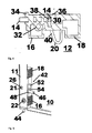
- Fig. 1 shows a section enlargement of the lower part of a cabinet door 10 for a device cabinet, not shown here, for example, for a distribution cabinet, with an inserted into a fold provided thereon 11 hinge 12 according to a first embodiment.
- hinge pin 14 Of the inserted into the fold 11 of the cabinet door 10 hinge 12 is in FIG. 1 only shown therein hinge pin 14 and two pointing away from the outer edge shelves 16, 18, which serve to adjust the hinge 12 for the purpose of aligning the cabinet door 10 in the installed position, as well as in the Fig. 3a and 3b is shown in more detail, and a triangular bracket 20, which leads to an in Fig. 4 heard in more detail spring device 20 heard.
- the hinge 12 is positively connected by means of a centering pin 21 with the cabinet door 10 and by means of a retaining screw, 22 frictionally attached thereto.
- the hinge 12 is inserted into the limited space of the cabinet door 10 and the fold 11 24 until it stops, wherein it engages in the correct end position with the arranged on the hinge centering 21 in a recess provided in the recess 11 recess 26. Then done the adjustment of the hinge 12 and its attachment to the cabinet door 10 by means of the retaining screw.
- Fig. 2 is indicated how the hinge 12 is inserted into the cabinet door 10.
- the end face of the vertically projecting from the hinge 12 projecting centering pin 21 is partially bevelled, so that the fold 11 is automatically raised during insertion of the hinge 12 in the closest possible match this adapted space 24 by the chamfer on the centering pin 21 until the hinge 12 has reached its horizontal end position, in which the centering pin 21 is aligned with the recess 26 provided for this purpose in the fold 11 and accordingly engages therein.
- FIG Fig. 2 an oval slot 28 which is formed in the fold 11 and serves to ensure that the fastening of the hinge 11 on the cabinet door 10 in a cylindrical recess 32 in the hinge 12 engaging retaining screw 22 has sufficient lateral movement margin for adjusting the hinge 11.
- Fig. 3a shows the adjustment of the inserted into the cabinet door 10 hinge 12 by applying (upper arrow) of the lower actuating surface 16 for aligning the cabinet door 10 in the equipment cabinet, not shown here.
- the hinge pin 14 is displaced outward (lower arrow), wherein the centering pin 21 rotatably held in the assigned recess 26 in the fold 11 forms the pivot point.
- Fig. 3b shows the adjustment of the hinge 12 inserted into the cabinet door 10 by applying (upper arrow) of the upper actuating surface 18 for aligning the cabinet door 10 in the equipment cabinet, not shown here.
- the hinge pin 14 By actuating the upper footprint 18, the hinge pin 14 is displaced inwardly (lower arrow), wherein in the assigned recess 26 in the fold 11 rotatably held centering pin 21 forms the pivot point.
- the hinge 12 is shown in plan view on a longitudinal side.
- the hinge 12 substantially consists of a hinge body 30, in which the hinge pin 14 close to the edge on the outside is used.
- the hinge pin 14 is performed according to the invention longitudinally displaceable in the hinge body 30; so as to allow a simple installation of the cabinet door 10, not shown here in the respective equipment cabinet.
- the guide of the hinge pin 14 adjacent outside of the hinge body is provided at the pin end with a stop 34 which closes the fold 11 in the installed state, and further with a web 36 which is supported on the fold 11 for the purpose of adjustment, So is for Adjustment of one of the shelves 16,18 of the hinge 12 is applied, so the reaction force is transmitted not only from the centering pin 21 on the cabinet door 10, but also from the web 36th
- Fig. 4 the function of the spring device 20, which acts as a bow spring with a triangular spring portion of the hinge pin 14
- the hinge pin 14 is provided at its inner end with a circumferential annular groove 38 into which the spring means 20 positively and non-positively engages and the hinge pin 14 applied to the outside.
- the guided out of the hinge body 30 triangular spring portion, which allows the spring pin 40 applied to the hinge pin to be operated manually against the applied spring force, so that in this way the hinge pin 14 is acted upon inwardly and the assembly of the hinge door 12 provided with 10th allowed in the relevant equipment cabinet. After releasing this triangular area, the spring force can again act fully and move the hinge pin 14 to the outside.
- the spring device can either be positively connected to the hinge body 30 as a separate part or integrally formed on the hinge body 30.
- Fig. 5 shows a detail enlargement of a cabinet door 10 for a likewise not shown here equipment cabinet, which is also provided with a fold 11, in which a hinge 42 is inserted, which is formed according to a second embodiment.
- the second embodiment largely corresponds to that in the US Pat Fig. 1 to 4 explained in detail first Embodiment.
- the dimensions as well as the means provided for adjusting the hinge 42 are identical to those of the first embodiment.
- a retaining screw 22 are provided with associated oval slot 28 in the fold 11 for fixing the hinge 42 inserted therein.
- the second embodiment of the hinge 42 differs from the first embodiment practically only by the hinge pin 44 which, unlike the first embodiment, is not exclusively rectilinear and is provided at its inside end with an annular groove for engaging a leaf spring, but at the second Embodiment also has the longitudinally displaceable guided in the hinge 42 hinge pin 44 at its inner end a laterally projecting Anformung, which is referred to below as a crosspiece 46.
- This crosspiece 46 may be formed as an integrally connected bend, but it may also be connected to the hinge pin in other ways, for example by means of welding or soldering or brazing.
- the hinge pin 44 is not acted upon as in the first embodiment by the triangular spring means 20 and by the associated leaf spring 40, but that the crosspiece 46 occupies two end positions, namely one in which the hinge pin 44 after extended on the outside, and one in which the hinge pin 44 is retracted inward.
- the support surface 52 is provided with a cam 54, which the crosspiece 46 must overcome in order to reach its other end position.
- the crosspiece 46 is subjected to an action by a further spring means 48, which may be formed, for example, as a bow spring and partially comprises the crosspiece.
- this spring means 48 is integrally formed on the hinge body 50 and prevents the cross piece changed its position at random.
- hinge pin 44 to change the respective end position, it requires at least for retraction of the hinge pin 44 a manual operation by the crosspiece 46 is raised so far that it can overcome the cam 54 against the force of the spring means 48, or it is with appropriate force Apply laterally to get to the other end position.
- the spring force as well as the design of the cam 54 is matched to the support surface 52, so that, for example, in a provided for assembly cabinet door 10, which is temporarily parked on the ground, the extended hinge pin 44 under the action of the weight of the cabinet door in his other end position is applied and this occupies, so that no damage to the hinge pin or even the hinge 42 is to get.
- Fig. 6 shows the hinge body 50 according to Fig. 5 in an oblique view of its lower in the installed position. Its structure corresponds, as stated above, largely the hinge body 30 according to the first embodiment. In that regard, all there already explained features are provided in an identical manner with the corresponding reference numerals.
- Fig. 7 shows the door in accordance with the Fig. 5 used hinge body 50 in an oblique view from the side, wherein between the two shelves 16, 18 of the sliding path for the cross piece 46 with the corresponding support surface 52 and disposed between the two respective end positions for the crosspiece 46 cam 54.
- the bow spring 48 is arranged, which acts on the crosspiece 46 and prevents the crosspiece 46 to automatically overcome the cam 54 serving as a slide lock.
- the hinge body can be formed both according to the first embodiment and according to the second embodiment.
- the present invention also includes any combinations of preferred embodiments and their design features or developments, unless they are mutually exclusive.
Landscapes
- Engineering & Computer Science (AREA)
- Mechanical Engineering (AREA)
- Hinges (AREA)
- Patch Boards (AREA)
- Casings For Electric Apparatus (AREA)
Applications Claiming Priority (1)
| Application Number | Priority Date | Filing Date | Title |
|---|---|---|---|
| DE201010008597 DE102010008597B3 (de) | 2010-02-19 | 2010-02-19 | Tür für einen Geräteschrank |
Publications (3)
| Publication Number | Publication Date |
|---|---|
| EP2362045A2 true EP2362045A2 (fr) | 2011-08-31 |
| EP2362045A3 EP2362045A3 (fr) | 2014-05-14 |
| EP2362045B1 EP2362045B1 (fr) | 2016-08-24 |
Family
ID=44009884
Family Applications (1)
| Application Number | Title | Priority Date | Filing Date |
|---|---|---|---|
| EP11001294.5A Active EP2362045B1 (fr) | 2010-02-19 | 2011-02-17 | Porte pour une armoire électrique |
Country Status (3)
| Country | Link |
|---|---|
| EP (1) | EP2362045B1 (fr) |
| DE (1) | DE102010008597B3 (fr) |
| RU (1) | RU2557508C2 (fr) |
Cited By (1)
| Publication number | Priority date | Publication date | Assignee | Title |
|---|---|---|---|---|
| CN113123692A (zh) * | 2019-12-30 | 2021-07-16 | 惠而浦有限公司 | 用于器具门板的铰链组件的弹性保持器 |
Families Citing this family (1)
| Publication number | Priority date | Publication date | Assignee | Title |
|---|---|---|---|---|
| EP3667004B1 (fr) | 2018-12-12 | 2023-03-01 | ABB Schweiz AG | Porte pour armoire d'appareil électrique |
Citations (2)
| Publication number | Priority date | Publication date | Assignee | Title |
|---|---|---|---|---|
| DE8800918U1 (de) | 1988-01-27 | 1988-03-10 | Hager Electro GmbH + Co, 6601 Ensheim | Scharnier einer Tür eines Schrankes, insbesondere in der elektrischen Hausinstallation |
| DE4108430A1 (de) | 1991-03-15 | 1992-09-17 | Schupa Elektro Gmbh & Co Kg | Vorrichtung zur genauen justage von schaltschranktueren |
Family Cites Families (4)
| Publication number | Priority date | Publication date | Assignee | Title |
|---|---|---|---|---|
| DE29502371U1 (de) * | 1995-02-14 | 1996-06-13 | Hager Electro GmbH, 66131 Saarbrücken | Scharnier einer aus abgekantetem Blech bestehenden Installationsschrank-Tür |
| US6526693B2 (en) * | 1996-10-16 | 2003-03-04 | Insta-Bed Floral Systems, Inc. | Renewable in ground planting apparatus and methods of making and using same |
| WO2001007742A1 (fr) * | 1999-07-13 | 2001-02-01 | The Stanley Works | Ensemble de porte avec raccord a charniere ameliore |
| DE10313842B4 (de) * | 2003-03-24 | 2009-04-23 | Hager Electro Gmbh | Schranktür |
-
2010
- 2010-02-19 DE DE201010008597 patent/DE102010008597B3/de not_active Expired - Fee Related
-
2011
- 2011-02-17 EP EP11001294.5A patent/EP2362045B1/fr active Active
- 2011-02-18 RU RU2011106321/12A patent/RU2557508C2/ru active
Patent Citations (2)
| Publication number | Priority date | Publication date | Assignee | Title |
|---|---|---|---|---|
| DE8800918U1 (de) | 1988-01-27 | 1988-03-10 | Hager Electro GmbH + Co, 6601 Ensheim | Scharnier einer Tür eines Schrankes, insbesondere in der elektrischen Hausinstallation |
| DE4108430A1 (de) | 1991-03-15 | 1992-09-17 | Schupa Elektro Gmbh & Co Kg | Vorrichtung zur genauen justage von schaltschranktueren |
Cited By (1)
| Publication number | Priority date | Publication date | Assignee | Title |
|---|---|---|---|---|
| CN113123692A (zh) * | 2019-12-30 | 2021-07-16 | 惠而浦有限公司 | 用于器具门板的铰链组件的弹性保持器 |
Also Published As
| Publication number | Publication date |
|---|---|
| RU2011106321A (ru) | 2012-08-27 |
| RU2557508C2 (ru) | 2015-07-20 |
| EP2362045A3 (fr) | 2014-05-14 |
| EP2362045B1 (fr) | 2016-08-24 |
| DE102010008597B3 (de) | 2011-06-22 |
Similar Documents
| Publication | Publication Date | Title |
|---|---|---|
| EP1709270B1 (fr) | Fixation de pinces pour le montage de dispositifs de ferrures, tels que fermetures, elements de charniere, poignees dans des passages au travers d'une paroi mince | |
| EP2851497B1 (fr) | Dispositif de montage réglable pour un élément coulissant et dispositif coulissant | |
| EP3580418B1 (fr) | Charnière pour meuble facile à monter | |
| EP3580420B1 (fr) | Charnière de meuble pourvue d'un élément de blocage pour un amortisseur linéaire | |
| EP2704604B1 (fr) | Tiroir | |
| EP2742199B1 (fr) | Système de fixation pour fixer une pièce sur une rainure d'une fenêtre, d'une porte ou analogue | |
| EP3271530B1 (fr) | Élément de maintien pour une poignée de porte ou de fenêtre et agencement d'une poignée de porte ou de fenêtre au niveau d'une ouverture de réception d'un cadre de fenêtre, d'un battant de porte ou similaire | |
| WO2018033221A1 (fr) | Charnière de meuble | |
| EP3625415B1 (fr) | Palier de volet équipé d'un accessoire de réglage | |
| EP2708692B1 (fr) | Ferrure destinée à être agencée de façon cachée dans la feuillure entre un battant et un cadre de fenêtre, de porte ou analogue | |
| DE102007054476B4 (de) | Kulissenanordnung | |
| EP1040245B1 (fr) | Tourniquet pour portes, volets ou similaires a paroi epaisse | |
| EP3621484A2 (fr) | Dispositif de retenue pour façade de tiroir | |
| EP2949844B1 (fr) | Agencement de bande pour portes, fenêtres ou analogues, doté d'un dispositif de réglage de jeu de joint | |
| EP2362045B1 (fr) | Porte pour une armoire électrique | |
| EP2262968B1 (fr) | Ensemble ferrure | |
| EP2760090A1 (fr) | Système de fixation et kit d'intégration pour le montage d'une passerelle de montage dans une armoire de commande | |
| DE202007011982U1 (de) | Verstellbares Band | |
| DE202016106504U1 (de) | Montagewerkzeug für die Montage einer Schaltschranktür an einem Schaltschrankgehäuse und eine entsprechende Schaltschrankanordnung | |
| EP2233039B1 (fr) | Guidage pour tiroirs | |
| EP2208843B1 (fr) | Charnière pour une porte | |
| DE102008036151A1 (de) | Scharnierband mit einer Unterkonstruktion zur Befestigung an einem Türblatt | |
| EP4424960A1 (fr) | Dispositif de charnière, charnière de butée et unité fonctionnelle | |
| EP1602794B1 (fr) | Ferrure de cadre | |
| EP3727091B1 (fr) | Arrangement comprenant une tringle et un element mural d'un tiroir |
Legal Events
| Date | Code | Title | Description |
|---|---|---|---|
| PUAI | Public reference made under article 153(3) epc to a published international application that has entered the european phase |
Free format text: ORIGINAL CODE: 0009012 |
|
| AK | Designated contracting states |
Kind code of ref document: A2 Designated state(s): AL AT BE BG CH CY CZ DE DK EE ES FI FR GB GR HR HU IE IS IT LI LT LU LV MC MK MT NL NO PL PT RO RS SE SI SK SM TR |
|
| AX | Request for extension of the european patent |
Extension state: BA ME |
|
| PUAL | Search report despatched |
Free format text: ORIGINAL CODE: 0009013 |
|
| AK | Designated contracting states |
Kind code of ref document: A3 Designated state(s): AL AT BE BG CH CY CZ DE DK EE ES FI FR GB GR HR HU IE IS IT LI LT LU LV MC MK MT NL NO PL PT RO RS SE SI SK SM TR |
|
| AX | Request for extension of the european patent |
Extension state: BA ME |
|
| RIC1 | Information provided on ipc code assigned before grant |
Ipc: E05D 7/10 20060101AFI20140404BHEP Ipc: E05D 7/04 20060101ALI20140404BHEP |
|
| 17P | Request for examination filed |
Effective date: 20140602 |
|
| 17Q | First examination report despatched |
Effective date: 20150923 |
|
| GRAP | Despatch of communication of intention to grant a patent |
Free format text: ORIGINAL CODE: EPIDOSNIGR1 |
|
| INTG | Intention to grant announced |
Effective date: 20160517 |
|
| GRAS | Grant fee paid |
Free format text: ORIGINAL CODE: EPIDOSNIGR3 |
|
| GRAA | (expected) grant |
Free format text: ORIGINAL CODE: 0009210 |
|
| AK | Designated contracting states |
Kind code of ref document: B1 Designated state(s): AL AT BE BG CH CY CZ DE DK EE ES FI FR GB GR HR HU IE IS IT LI LT LU LV MC MK MT NL NO PL PT RO RS SE SI SK SM TR |
|
| REG | Reference to a national code |
Ref country code: GB Ref legal event code: FG4D Free format text: NOT ENGLISH |
|
| REG | Reference to a national code |
Ref country code: CH Ref legal event code: EP |
|
| REG | Reference to a national code |
Ref country code: AT Ref legal event code: REF Ref document number: 823275 Country of ref document: AT Kind code of ref document: T Effective date: 20160915 |
|
| REG | Reference to a national code |
Ref country code: IE Ref legal event code: FG4D Free format text: LANGUAGE OF EP DOCUMENT: GERMAN |
|
| REG | Reference to a national code |
Ref country code: DE Ref legal event code: R096 Ref document number: 502011010468 Country of ref document: DE |
|
| REG | Reference to a national code |
Ref country code: NL Ref legal event code: FP |
|
| REG | Reference to a national code |
Ref country code: LT Ref legal event code: MG4D |
|
| PG25 | Lapsed in a contracting state [announced via postgrant information from national office to epo] |
Ref country code: HR Free format text: LAPSE BECAUSE OF FAILURE TO SUBMIT A TRANSLATION OF THE DESCRIPTION OR TO PAY THE FEE WITHIN THE PRESCRIBED TIME-LIMIT Effective date: 20160824 Ref country code: NO Free format text: LAPSE BECAUSE OF FAILURE TO SUBMIT A TRANSLATION OF THE DESCRIPTION OR TO PAY THE FEE WITHIN THE PRESCRIBED TIME-LIMIT Effective date: 20161124 Ref country code: IT Free format text: LAPSE BECAUSE OF FAILURE TO SUBMIT A TRANSLATION OF THE DESCRIPTION OR TO PAY THE FEE WITHIN THE PRESCRIBED TIME-LIMIT Effective date: 20160824 Ref country code: RS Free format text: LAPSE BECAUSE OF FAILURE TO SUBMIT A TRANSLATION OF THE DESCRIPTION OR TO PAY THE FEE WITHIN THE PRESCRIBED TIME-LIMIT Effective date: 20160824 Ref country code: FI Free format text: LAPSE BECAUSE OF FAILURE TO SUBMIT A TRANSLATION OF THE DESCRIPTION OR TO PAY THE FEE WITHIN THE PRESCRIBED TIME-LIMIT Effective date: 20160824 Ref country code: LT Free format text: LAPSE BECAUSE OF FAILURE TO SUBMIT A TRANSLATION OF THE DESCRIPTION OR TO PAY THE FEE WITHIN THE PRESCRIBED TIME-LIMIT Effective date: 20160824 |
|
| PG25 | Lapsed in a contracting state [announced via postgrant information from national office to epo] |
Ref country code: PT Free format text: LAPSE BECAUSE OF FAILURE TO SUBMIT A TRANSLATION OF THE DESCRIPTION OR TO PAY THE FEE WITHIN THE PRESCRIBED TIME-LIMIT Effective date: 20161226 Ref country code: LV Free format text: LAPSE BECAUSE OF FAILURE TO SUBMIT A TRANSLATION OF THE DESCRIPTION OR TO PAY THE FEE WITHIN THE PRESCRIBED TIME-LIMIT Effective date: 20160824 Ref country code: SE Free format text: LAPSE BECAUSE OF FAILURE TO SUBMIT A TRANSLATION OF THE DESCRIPTION OR TO PAY THE FEE WITHIN THE PRESCRIBED TIME-LIMIT Effective date: 20160824 Ref country code: ES Free format text: LAPSE BECAUSE OF FAILURE TO SUBMIT A TRANSLATION OF THE DESCRIPTION OR TO PAY THE FEE WITHIN THE PRESCRIBED TIME-LIMIT Effective date: 20160824 Ref country code: GR Free format text: LAPSE BECAUSE OF FAILURE TO SUBMIT A TRANSLATION OF THE DESCRIPTION OR TO PAY THE FEE WITHIN THE PRESCRIBED TIME-LIMIT Effective date: 20161125 |
|
| PG25 | Lapsed in a contracting state [announced via postgrant information from national office to epo] |
Ref country code: RO Free format text: LAPSE BECAUSE OF FAILURE TO SUBMIT A TRANSLATION OF THE DESCRIPTION OR TO PAY THE FEE WITHIN THE PRESCRIBED TIME-LIMIT Effective date: 20160824 Ref country code: EE Free format text: LAPSE BECAUSE OF FAILURE TO SUBMIT A TRANSLATION OF THE DESCRIPTION OR TO PAY THE FEE WITHIN THE PRESCRIBED TIME-LIMIT Effective date: 20160824 |
|
| REG | Reference to a national code |
Ref country code: DE Ref legal event code: R097 Ref document number: 502011010468 Country of ref document: DE |
|
| PG25 | Lapsed in a contracting state [announced via postgrant information from national office to epo] |
Ref country code: SM Free format text: LAPSE BECAUSE OF FAILURE TO SUBMIT A TRANSLATION OF THE DESCRIPTION OR TO PAY THE FEE WITHIN THE PRESCRIBED TIME-LIMIT Effective date: 20160824 Ref country code: BG Free format text: LAPSE BECAUSE OF FAILURE TO SUBMIT A TRANSLATION OF THE DESCRIPTION OR TO PAY THE FEE WITHIN THE PRESCRIBED TIME-LIMIT Effective date: 20161124 Ref country code: DK Free format text: LAPSE BECAUSE OF FAILURE TO SUBMIT A TRANSLATION OF THE DESCRIPTION OR TO PAY THE FEE WITHIN THE PRESCRIBED TIME-LIMIT Effective date: 20160824 Ref country code: PL Free format text: LAPSE BECAUSE OF FAILURE TO SUBMIT A TRANSLATION OF THE DESCRIPTION OR TO PAY THE FEE WITHIN THE PRESCRIBED TIME-LIMIT Effective date: 20160824 Ref country code: CZ Free format text: LAPSE BECAUSE OF FAILURE TO SUBMIT A TRANSLATION OF THE DESCRIPTION OR TO PAY THE FEE WITHIN THE PRESCRIBED TIME-LIMIT Effective date: 20160824 Ref country code: SK Free format text: LAPSE BECAUSE OF FAILURE TO SUBMIT A TRANSLATION OF THE DESCRIPTION OR TO PAY THE FEE WITHIN THE PRESCRIBED TIME-LIMIT Effective date: 20160824 |
|
| PLBE | No opposition filed within time limit |
Free format text: ORIGINAL CODE: 0009261 |
|
| STAA | Information on the status of an ep patent application or granted ep patent |
Free format text: STATUS: NO OPPOSITION FILED WITHIN TIME LIMIT |
|
| 26N | No opposition filed |
Effective date: 20170526 |
|
| PG25 | Lapsed in a contracting state [announced via postgrant information from national office to epo] |
Ref country code: SI Free format text: LAPSE BECAUSE OF FAILURE TO SUBMIT A TRANSLATION OF THE DESCRIPTION OR TO PAY THE FEE WITHIN THE PRESCRIBED TIME-LIMIT Effective date: 20160824 |
|
| PG25 | Lapsed in a contracting state [announced via postgrant information from national office to epo] |
Ref country code: MC Free format text: LAPSE BECAUSE OF FAILURE TO SUBMIT A TRANSLATION OF THE DESCRIPTION OR TO PAY THE FEE WITHIN THE PRESCRIBED TIME-LIMIT Effective date: 20160824 |
|
| REG | Reference to a national code |
Ref country code: CH Ref legal event code: PL |
|
| GBPC | Gb: european patent ceased through non-payment of renewal fee |
Effective date: 20170217 |
|
| PG25 | Lapsed in a contracting state [announced via postgrant information from national office to epo] |
Ref country code: CH Free format text: LAPSE BECAUSE OF NON-PAYMENT OF DUE FEES Effective date: 20170228 Ref country code: LI Free format text: LAPSE BECAUSE OF NON-PAYMENT OF DUE FEES Effective date: 20170228 |
|
| REG | Reference to a national code |
Ref country code: IE Ref legal event code: MM4A |
|
| REG | Reference to a national code |
Ref country code: FR Ref legal event code: ST Effective date: 20171031 |
|
| PG25 | Lapsed in a contracting state [announced via postgrant information from national office to epo] |
Ref country code: FR Free format text: LAPSE BECAUSE OF NON-PAYMENT OF DUE FEES Effective date: 20170228 |
|
| PG25 | Lapsed in a contracting state [announced via postgrant information from national office to epo] |
Ref country code: GB Free format text: LAPSE BECAUSE OF NON-PAYMENT OF DUE FEES Effective date: 20170217 Ref country code: IE Free format text: LAPSE BECAUSE OF NON-PAYMENT OF DUE FEES Effective date: 20170217 |
|
| PG25 | Lapsed in a contracting state [announced via postgrant information from national office to epo] |
Ref country code: MT Free format text: LAPSE BECAUSE OF FAILURE TO SUBMIT A TRANSLATION OF THE DESCRIPTION OR TO PAY THE FEE WITHIN THE PRESCRIBED TIME-LIMIT Effective date: 20160824 |
|
| PG25 | Lapsed in a contracting state [announced via postgrant information from national office to epo] |
Ref country code: AL Free format text: LAPSE BECAUSE OF FAILURE TO SUBMIT A TRANSLATION OF THE DESCRIPTION OR TO PAY THE FEE WITHIN THE PRESCRIBED TIME-LIMIT Effective date: 20160824 |
|
| PG25 | Lapsed in a contracting state [announced via postgrant information from national office to epo] |
Ref country code: HU Free format text: LAPSE BECAUSE OF FAILURE TO SUBMIT A TRANSLATION OF THE DESCRIPTION OR TO PAY THE FEE WITHIN THE PRESCRIBED TIME-LIMIT; INVALID AB INITIO Effective date: 20110217 |
|
| REG | Reference to a national code |
Ref country code: LU Ref legal event code: PD Owner name: ABB SCHWEIZ AG; CH Free format text: FORMER OWNER: ABB AG Effective date: 20190529 |
|
| REG | Reference to a national code |
Ref country code: BE Ref legal event code: PD Owner name: ABB SCHWEIZ AG; CH Free format text: DETAILS ASSIGNMENT: CHANGE OF OWNER(S), CESSION; FORMER OWNER NAME: ABB AG Effective date: 20190702 |
|
| REG | Reference to a national code |
Ref country code: NL Ref legal event code: PD Owner name: ABB SCHWEIZ AG; CH Free format text: DETAILS ASSIGNMENT: CHANGE OF OWNER(S), ASSIGNMENT; FORMER OWNER NAME: ABB AG Effective date: 20190926 |
|
| REG | Reference to a national code |
Ref country code: AT Ref legal event code: PC Ref document number: 823275 Country of ref document: AT Kind code of ref document: T Owner name: ABB SCHWEIZ AG, CH Effective date: 20190829 |
|
| PG25 | Lapsed in a contracting state [announced via postgrant information from national office to epo] |
Ref country code: CY Free format text: LAPSE BECAUSE OF NON-PAYMENT OF DUE FEES Effective date: 20160824 |
|
| PG25 | Lapsed in a contracting state [announced via postgrant information from national office to epo] |
Ref country code: MK Free format text: LAPSE BECAUSE OF FAILURE TO SUBMIT A TRANSLATION OF THE DESCRIPTION OR TO PAY THE FEE WITHIN THE PRESCRIBED TIME-LIMIT Effective date: 20160824 |
|
| REG | Reference to a national code |
Ref country code: DE Ref legal event code: R081 Ref document number: 502011010468 Country of ref document: DE Owner name: ABB SCHWEIZ AG, CH Free format text: FORMER OWNER: ABB AG, 68165 MANNHEIM, DE |
|
| PG25 | Lapsed in a contracting state [announced via postgrant information from national office to epo] |
Ref country code: TR Free format text: LAPSE BECAUSE OF FAILURE TO SUBMIT A TRANSLATION OF THE DESCRIPTION OR TO PAY THE FEE WITHIN THE PRESCRIBED TIME-LIMIT Effective date: 20160824 |
|
| PG25 | Lapsed in a contracting state [announced via postgrant information from national office to epo] |
Ref country code: IS Free format text: LAPSE BECAUSE OF FAILURE TO SUBMIT A TRANSLATION OF THE DESCRIPTION OR TO PAY THE FEE WITHIN THE PRESCRIBED TIME-LIMIT Effective date: 20161224 |
|
| PGFP | Annual fee paid to national office [announced via postgrant information from national office to epo] |
Ref country code: LU Payment date: 20260218 Year of fee payment: 16 Ref country code: NL Payment date: 20260218 Year of fee payment: 16 |
|
| PGFP | Annual fee paid to national office [announced via postgrant information from national office to epo] |
Ref country code: DE Payment date: 20260218 Year of fee payment: 16 |
|
| PGFP | Annual fee paid to national office [announced via postgrant information from national office to epo] |
Ref country code: AT Payment date: 20260219 Year of fee payment: 16 |
|
| PGFP | Annual fee paid to national office [announced via postgrant information from national office to epo] |
Ref country code: BE Payment date: 20260218 Year of fee payment: 16 |