EP2362047A2 - Porte à levage coulissante ou fenêtre à levage coulissant - Google Patents
Porte à levage coulissante ou fenêtre à levage coulissant Download PDFInfo
- Publication number
- EP2362047A2 EP2362047A2 EP20110001405 EP11001405A EP2362047A2 EP 2362047 A2 EP2362047 A2 EP 2362047A2 EP 20110001405 EP20110001405 EP 20110001405 EP 11001405 A EP11001405 A EP 11001405A EP 2362047 A2 EP2362047 A2 EP 2362047A2
- Authority
- EP
- European Patent Office
- Prior art keywords
- lift
- slide
- lifting
- frame
- sash
- Prior art date
- Legal status (The legal status is an assumption and is not a legal conclusion. Google has not performed a legal analysis and makes no representation as to the accuracy of the status listed.)
- Granted
Links
- 230000000295 complement effect Effects 0.000 claims abstract description 6
- 235000001674 Agaricus brunnescens Nutrition 0.000 claims description 14
- 238000007789 sealing Methods 0.000 description 3
- 241000638935 Senecio crassissimus Species 0.000 description 2
- 238000004026 adhesive bonding Methods 0.000 description 1
- 230000001419 dependent effect Effects 0.000 description 1
- 238000006073 displacement reaction Methods 0.000 description 1
- 230000005489 elastic deformation Effects 0.000 description 1
- 230000001771 impaired effect Effects 0.000 description 1
- 238000009434 installation Methods 0.000 description 1
- 230000000149 penetrating effect Effects 0.000 description 1
- 230000000007 visual effect Effects 0.000 description 1
Images
Classifications
-
- E—FIXED CONSTRUCTIONS
- E05—LOCKS; KEYS; WINDOW OR DOOR FITTINGS; SAFES
- E05D—HINGES OR SUSPENSION DEVICES FOR DOORS, WINDOWS OR WINGS
- E05D15/00—Suspension arrangements for wings
- E05D15/56—Suspension arrangements for wings with successive different movements
- E05D15/565—Suspension arrangements for wings with successive different movements for raising wings before sliding
-
- E—FIXED CONSTRUCTIONS
- E05—LOCKS; KEYS; WINDOW OR DOOR FITTINGS; SAFES
- E05F—DEVICES FOR MOVING WINGS INTO OPEN OR CLOSED POSITION; CHECKS FOR WINGS; WING FITTINGS NOT OTHERWISE PROVIDED FOR, CONCERNED WITH THE FUNCTIONING OF THE WING
- E05F5/00—Braking devices, e.g. checks; Stops; Buffers
- E05F5/06—Buffers or stops limiting opening of swinging wings, e.g. floor or wall stops
-
- E—FIXED CONSTRUCTIONS
- E05—LOCKS; KEYS; WINDOW OR DOOR FITTINGS; SAFES
- E05Y—INDEXING SCHEME ASSOCIATED WITH SUBCLASSES E05D AND E05F, RELATING TO CONSTRUCTION ELEMENTS, ELECTRIC CONTROL, POWER SUPPLY, POWER SIGNAL OR TRANSMISSION, USER INTERFACES, MOUNTING OR COUPLING, DETAILS, ACCESSORIES, AUXILIARY OPERATIONS NOT OTHERWISE PROVIDED FOR, APPLICATION THEREOF
- E05Y2800/00—Details, accessories and auxiliary operations not otherwise provided for
- E05Y2800/10—Additional functions
- E05Y2800/12—Sealing
-
- E—FIXED CONSTRUCTIONS
- E05—LOCKS; KEYS; WINDOW OR DOOR FITTINGS; SAFES
- E05Y—INDEXING SCHEME ASSOCIATED WITH SUBCLASSES E05D AND E05F, RELATING TO CONSTRUCTION ELEMENTS, ELECTRIC CONTROL, POWER SUPPLY, POWER SIGNAL OR TRANSMISSION, USER INTERFACES, MOUNTING OR COUPLING, DETAILS, ACCESSORIES, AUXILIARY OPERATIONS NOT OTHERWISE PROVIDED FOR, APPLICATION THEREOF
- E05Y2900/00—Application of doors, windows, wings or fittings thereof
- E05Y2900/10—Application of doors, windows, wings or fittings thereof for buildings or parts thereof
- E05Y2900/13—Type of wing
- E05Y2900/132—Doors
-
- E—FIXED CONSTRUCTIONS
- E05—LOCKS; KEYS; WINDOW OR DOOR FITTINGS; SAFES
- E05Y—INDEXING SCHEME ASSOCIATED WITH SUBCLASSES E05D AND E05F, RELATING TO CONSTRUCTION ELEMENTS, ELECTRIC CONTROL, POWER SUPPLY, POWER SIGNAL OR TRANSMISSION, USER INTERFACES, MOUNTING OR COUPLING, DETAILS, ACCESSORIES, AUXILIARY OPERATIONS NOT OTHERWISE PROVIDED FOR, APPLICATION THEREOF
- E05Y2900/00—Application of doors, windows, wings or fittings thereof
- E05Y2900/10—Application of doors, windows, wings or fittings thereof for buildings or parts thereof
- E05Y2900/13—Type of wing
- E05Y2900/148—Windows
-
- E—FIXED CONSTRUCTIONS
- E06—DOORS, WINDOWS, SHUTTERS, OR ROLLER BLINDS IN GENERAL; LADDERS
- E06B—FIXED OR MOVABLE CLOSURES FOR OPENINGS IN BUILDINGS, VEHICLES, FENCES OR LIKE ENCLOSURES IN GENERAL, e.g. DOORS, WINDOWS, BLINDS, GATES
- E06B3/00—Window sashes, door leaves, or like elements for closing wall or like openings; Layout of fixed or moving closures, e.g. windows in wall or like openings; Features of rigidly-mounted outer frames relating to the mounting of wing frames
- E06B3/32—Arrangements of wings characterised by the manner of movement; Arrangements of movable wings in openings; Features of wings or frames relating solely to the manner of movement of the wing
- E06B3/50—Arrangements of wings characterised by the manner of movement; Arrangements of movable wings in openings; Features of wings or frames relating solely to the manner of movement of the wing with more than one kind of movement
- E06B3/52—Wings requiring lifting before opening
Definitions
- the present invention relates to a lift-slide door or to a lift-and-slide window with at least one lift-slide wing, with at least one recorded in a lower frame part of the sash of the lift-slide sash carriage on a running rail , which is mounted on a lower frame part of a frame, is slidably guided, wherein in the closed lifting-sliding sash in a joint area between the lift-slide sash and a side frame part of the frame frame, a fixing element is provided, which is fixed in the joint area on the sash is and rests over the lifting-sliding sash in the lowered state on the running rail.
- lift-and-slide wings are known in the art.
- this describes DE 20 2008 013 043 U1 a lift-slide door or a lift-and-slide window with at least one lift-slide wing, which is slidably guided with at least one carriage received in a carriage groove of its casement on a running rail of a frame or threshold profile of a floor or window frame, wherein at a closed lifting-sliding sash exposed joint area of this wing whose sash a sealing element is provided, the closed rail and sliding the sliding carriage for frontal sealing of the carriage groove against the running rail and against the running rail having frame or threshold profile on both sides from the running rail rests.
- the sealing element used has the disadvantage that the lifting-sliding sash is guided only by the guide rail and the carriage. Since the carriage is supported with play, the lift-slide wing is laterally displaceable in wind load, whereby the driving rain safety is impaired, resulting in a leakage of the lift-slide sash.
- the cover member according to the DE 20 2008 013 043 U1 covered by a cover which must have an additional recess for the passage of the running rail.
- the object of the present invention is to refine a lift-and-slide door or a lift-and-slide window such that the disadvantages of the prior art are overcome.
- the lifting-sliding door according to the invention or the lifting-sliding window according to the invention should have an increased impermeability to driving rain and be easy to assemble.
- the object underlying the present invention is achieved by a lift-slide door or a lift-and-slide window with at least one lift-slide sash with the features of claim 1.
- Preferred embodiments of the present invention are described in the dependent claims.
- the tightness of a lift-and-slide door or window against driving rain can be improved by constructing the fixing element from a base and a fastening part, wherein the base is in the lower area a recess which is at least partially complementary to the contour of the carriage rail and in which in the lowered state of the lifting-sliding sash, a portion of the carriage rail is added.
- the present invention is to provide a lift-slide door or a lift-and-slide window with at least one lift-slide sash, which at least one carriage included in a lower frame part of the sash of the lift-slide sash on a Running rail, which is mounted on a lower frame part of a frame, slidably guided, wherein in the closed lifting-sliding sash in a joint area between the lift-slide sash and a side frame part of the frame frame, a fixing element is present, in the joint area on the sash is attached and rests on the sliding rail over the lifting-sliding wing in the lowered state, wherein the fixing element is constructed of a base and a fastening part, wherein the base in the lower region has a recess which is at least partially complementary to the contour of the carriage rail and in the lowered state of lifting Sliding wing a section of the carriage rail is added.
- the width of the base corresponds to the depth of the sash. It is likewise preferred if the base has a substantially rectangular shape. This ensures that the fastening part is flush with the casement.
- the fixing element is screwed by a screw to the casement, wherein the head of the screw is received in a screw receptacle of the fastening part.
- the fixing element is securely attached to the casement.
- a cover profile is attached to the lift and slide wings, which rests on the upper side of the base of the fixing element and which covers the fastening part of the fixing element.
- a cover profile ensures a market-oriented visual appearance of the lifting-sliding door according to the invention or the lifting-sliding window according to the invention.
- it is ensured that in the cover for adapting to the contour of the track no recess must be milled. As a result, the installation effort for the lifting-sliding door according to the invention or the lifting-sliding window according to the invention is considerably reduced.
- cover profile is locked to the sash of the lift-slide sash. Such a latching of the cover profile with the casement ensures a secure fit of the cover profile on the casement.
- the lift-slide wing further comprises a mushroom buffer, which rests on the fixing element and is attached to the cover.
- a mushroom buffer ensures a controlled stopping of the lifting-sliding sash.
- the foot of the mushroom buffer is passed through a hole in the cover profile. It may also be helpful if the foot of the mushroom buffer is received in the screw receptacle of the fastening part. As a result, on the one hand ensures a secure fit of the mushroom buffer and on the other hand provided sufficient space in the longitudinal direction with elastic deformation of the mushroom buffer available.
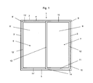
- FIG. 1 is the basic structure of a lift-slide door 1 shown schematically.
- the lift-slide door 1 comprises an outer frame frame 2 to be inserted into a building opening, which is constructed from two lateral frame parts 3, 3 ', an upper frame part 4 and a lower frame part 5, which is also referred to as a threshold, a fixed leaf 6 and a lifting-sliding sash 7, wherein passive leaf 6 and lifting-sliding sash 7 are inserted into the frame 2.
- the frames 8, 8 '(in this embodiment of the present invention are plastic hollow profile frames) of the lifting-sliding sash 7 or passive leaf 6 is in each case a glazing 9, 9 'used.
- the frames 8, 8 'of lifting-sliding sash 7 and fixed wing 6 are constructed analogously to the frame 2 from four frame elements, namely two lateral frame members 12, 12', 13, 13 ', each an upper frame member 10, 10' and in each case a lower frame part 11, 11
- the lateral frame part 13 of the lifting-sliding sash 7 is located on the lateral frame part 13 '(in FIG FIG. 1 not shown) of the inactive leaf 6, ie in the center joint
- the other lateral frame part 12 of the lifting-sliding sash 7 is located on the lateral frame part 3 of the frame 2, ie in the local joint area 15 between lifting sliding sash 7 and side frame part.
- two or more lift-slide wings 7 may be inserted into the frame 2.
- lifting-sliding sash 7 and vertical leaf 6 are arranged in two different mutually parallel planes.
- the lifting-sliding sash 7 is disposed in a plane closer to the building exterior level than the inactive leaf 6.
- On the frame parts 10, 11, 12 and 13 of the plastic hollow profile frame 8 of the lifting-sliding sash 7 are circumferentially, ie in Folding area, grooves for receiving hardware elements available.
- the lower frame part 11 of the lifting-sliding sash 7 has at its two lateral ends depending on a carriage 14 with rollers (not shown), through which the lifting-sliding sash 7 on a running rail 16 on the lower frame part 5 of the frame 2 slidably guided.
- the carriage 14 is in each case received in the lower frame part 11.
- a lifting-sliding fitting is attached to the plastic hollow profile frame 8 of the lifting-sliding sash 7, can be raised and lowered by the lifting-sliding sash 7 for opening and closing in the vertical direction.
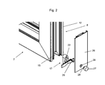
- FIG. 2 shows a section of the joint area 15 between lifting-sliding wings 7 and side frame part 3 of the frame 2 in an exploded view of an embodiment of the lifting-sliding door according to the invention 1.
- a fixing element 17 which in FIG. 4 is shown attached to the lateral frame part 12 of the frame 8 of the lifting-sliding sash 7.
- the fixing element 17 is constructed from a base 18 and a fastening part 19, which is attached to the base via at least one connection, preferably at least one web 20.
- the fastening part 19 is connected to the base 18 via three webs 20. Webs 20 and attachment member 19 are arranged opposite the base 18 in an offset plane.
- the base 18 has a rectangular shape, wherein the width of the base 18 corresponds to the depth of the frame 8. As a result, the base 18 is flush with the frame 8.
- the fastening part 19 there is a screw receptacle 22.
- the base 18 At the bottom of the base 18, i. In the region of the running rail 16 in the mounted state, the base 18 has a recess 21.
- the recess 21 has a shape which is complementary to a part of the upper contour of the carriage rail.
- the fixing element 17 is screwed by a screw 25 with the lateral frame part 12 of the sash 8.
- the head of the screw 25 is received in the screw receptacle 22 of the fastening part 19.
- FIG. 3 closes the bottom 30 of the base 18 flush with the lower frame part 11 of the frame 2 from frame.
- the fixing element 17 is connected via the locking elements 24 with the lateral frame part 12 of the lifting-sliding sash 7 by clamping.
- a cover 26 On the top 23 of the base 18 is a cover 26 on.
- the cover 26 is connected to the lateral frame part 12 of the lift-slide sash 7, preferably latched.
- the width of the cover profile 26 also corresponds to the profile depth of the frame 8 of the lift-slide sash 7. Since the fastening part 19 and the webs 20 are offset from the base 18 in the direction of the frame part 12, fastening part 19 and webs 20 through the cover profile 26th covered.
- the foot 28 of a mushroom buffer 27 is guided.
- the hole 29 is positioned in the cover strip such that the side of the frame member 12 facing the end of the hole 29 penetrating the foot 28 is inserted into the screw receptacle 22 of the fixing element 17.
- the mushroom buffer 27 rests against the fixing element 17.
- the attachment of the mushroom buffer 27 takes place on cover profile 26, for example by gluing or clamping fit.
- the mushroom buffer 27 ensures a controlled stopping of the lifting-sliding sash 7 when hitting the lateral frame part 3 of the frame 2.
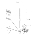
- FIG. 3 is the in FIG. 2 shown embodiment of the present invention shown in the assembled state. It can be seen that fastening part 19 and webs 20 are covered by the cover 26.
- a section of the running rail 16 is received in the recess 21 of the base 18 of the fixing element 17.
- shape of the recess 21 of the lifting-sliding wing 7 fits precisely on the track rail 16.
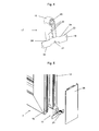
- FIG. 5 Another embodiment of the present invention is in FIG. 5 shown in an exploded view.
- the illustrated lift-slide wing 7 has a to the in FIG. 2 illustrated analog structure with the exception, in the embodiment according to FIG. 5 no mushroom buffer 27 is connected to the lateral frame part 12 of the frame 18.
- a buffer on the lateral frame part 3 of the frame 2 is provided.
Landscapes
- Engineering & Computer Science (AREA)
- Mechanical Engineering (AREA)
- Wing Frames And Configurations (AREA)
- Window Of Vehicle (AREA)
Applications Claiming Priority (1)
| Application Number | Priority Date | Filing Date | Title |
|---|---|---|---|
| DE202010002825U DE202010002825U1 (de) | 2010-02-25 | 2010-02-25 | Hebe-Schiebe-Fenster oder Hebe-Schiebe-Tür |
Publications (3)
| Publication Number | Publication Date |
|---|---|
| EP2362047A2 true EP2362047A2 (fr) | 2011-08-31 |
| EP2362047A3 EP2362047A3 (fr) | 2013-05-01 |
| EP2362047B1 EP2362047B1 (fr) | 2015-10-14 |
Family
ID=44166495
Family Applications (1)
| Application Number | Title | Priority Date | Filing Date |
|---|---|---|---|
| EP11001405.7A Active EP2362047B1 (fr) | 2010-02-25 | 2011-02-21 | Porte à levage coulissante ou fenêtre à levage coulissant |
Country Status (2)
| Country | Link |
|---|---|
| EP (1) | EP2362047B1 (fr) |
| DE (1) | DE202010002825U1 (fr) |
Cited By (1)
| Publication number | Priority date | Publication date | Assignee | Title |
|---|---|---|---|---|
| CN108699876A (zh) * | 2015-12-23 | 2018-10-23 | 马科技术有限责任公司 | 带有框架侧的调节元件的衬板装置 |
Citations (1)
| Publication number | Priority date | Publication date | Assignee | Title |
|---|---|---|---|---|
| DE202008013043U1 (de) | 2008-10-02 | 2009-02-12 | Gretsch-Unitas GmbH Baubeschläge | Hebe-Schiebe-Fenster oder -Tür sowie Abdichtelement |
Family Cites Families (5)
| Publication number | Priority date | Publication date | Assignee | Title |
|---|---|---|---|---|
| DE3127929C2 (de) * | 1981-07-15 | 1984-05-30 | Siegenia-Frank Kg, 5900 Siegen | Treibstangenbeschlag mit an Rahmenprofilen aus Metall, Kunststoff od.dgl. von Fenstern oder Türen in hinterschnittenen Führungskanälen geführten Treibstangen |
| DE20304001U1 (de) * | 2003-01-10 | 2003-05-08 | Gretsch-Unitas GmbH Baubeschläge, 71254 Ditzingen | Beschlag für Hebe-Schiebe-Türen oder -Fenster sowie Laufschuh für einen solchen Beschlag |
| US20050217182A1 (en) * | 2004-03-31 | 2005-10-06 | Halsey Jay F | Method and device for buttressing a sliding door |
| US7637058B2 (en) * | 2005-03-09 | 2009-12-29 | Chin-Ming Lai | Wind and rain preventing device for aluminum doors and windows |
| DE202008001251U1 (de) * | 2008-01-28 | 2008-04-17 | Gretsch-Unitas GmbH Baubeschläge | Auf einer Laufschiene verfahrbare Hebeschiebetür |
-
2010
- 2010-02-25 DE DE202010002825U patent/DE202010002825U1/de not_active Expired - Lifetime
-
2011
- 2011-02-21 EP EP11001405.7A patent/EP2362047B1/fr active Active
Patent Citations (1)
| Publication number | Priority date | Publication date | Assignee | Title |
|---|---|---|---|---|
| DE202008013043U1 (de) | 2008-10-02 | 2009-02-12 | Gretsch-Unitas GmbH Baubeschläge | Hebe-Schiebe-Fenster oder -Tür sowie Abdichtelement |
Cited By (2)
| Publication number | Priority date | Publication date | Assignee | Title |
|---|---|---|---|---|
| CN108699876A (zh) * | 2015-12-23 | 2018-10-23 | 马科技术有限责任公司 | 带有框架侧的调节元件的衬板装置 |
| CN108699876B (zh) * | 2015-12-23 | 2020-02-04 | 马科技术有限责任公司 | 带有框架侧的调节元件的衬板装置 |
Also Published As
| Publication number | Publication date |
|---|---|
| DE202010002825U1 (de) | 2011-07-12 |
| EP2362047A3 (fr) | 2013-05-01 |
| EP2362047B1 (fr) | 2015-10-14 |
Similar Documents
| Publication | Publication Date | Title |
|---|---|---|
| EP2132392B1 (fr) | Porte levante coulissante | |
| CH624729A5 (fr) | ||
| WO2015085336A2 (fr) | Dispositif destiné à fermer une ouverture dans un bâtiment | |
| EP3296501B1 (fr) | Portail doté d'un élément de porte ainsi qu'élément de fermeture inférieur pour un élément de portail doté d'un élément de porte intégré | |
| DE202008013043U1 (de) | Hebe-Schiebe-Fenster oder -Tür sowie Abdichtelement | |
| DE19846308A1 (de) | Beschlag für Fenster oder Türen | |
| EP2473691B1 (fr) | Logement à chariot pour une porte levante coulissante ou une fenêtre levante coulissante, et porte levante coulissante ou fenêtre levante coulissante comprenant un tel logement à chariot | |
| DE202016101390U1 (de) | Mitteldichtungsblock und Mitteldichtungsblocksystem für eine Hebeschiebtür | |
| DE4338181C1 (de) | Kunststoff-Hohlprofil | |
| EP0833998B1 (fr) | Profile creux de cadre de fenetre et chassis de fenetre a deux battants utilisant ce profile | |
| EP3112577A1 (fr) | Joint abaissable | |
| EP2362047B1 (fr) | Porte à levage coulissante ou fenêtre à levage coulissant | |
| EP3715578A1 (fr) | Porte de protection contre les insectes | |
| WO2019179940A1 (fr) | Unité d'étanchéité | |
| EP0833028B1 (fr) | Butée d'arrêt de glissière de guidage pour arrêt de fenêtre ou de porte | |
| DE202004000610U1 (de) | Beschlag für eine Ausstell- und Kippbewegung eines Flügels eines Gebäudefensters oder einer Gebäudetür sowie Parallelschiebekipp-Fenster oder -Tür mit einem solchen Beschlag | |
| DE202017106040U1 (de) | Türsystem | |
| DE20000335U1 (de) | Vorsatztür oder -fenster, insbesondere Insektenschutzgitter | |
| DE20306960U1 (de) | Beschlageinheit für Fenster oder Türen | |
| DE2520668A1 (de) | Treibstangenbeschlag fuer fenster, tueren oder dergleichen | |
| AT518432B1 (de) | Dichtungsvorrichtung mit bewegbarer Dichtleiste | |
| EP2823126B1 (fr) | Fenêtre, porte ou similaire, comprenant un élément de fermeture | |
| EP3530861A1 (fr) | Élément horizontal de cadre pour un cadre de porte coulissante et / ou de fenêtre coulissante, cadre de porte coulissante et / ou de fenêtre coulissante ainsi que système de porte coulissante et / ou de fenêtre coulissante | |
| DE814219C (de) | Rahmen aus Hohlprofilen, insbesondere Fensterrahmen | |
| DE202025100919U1 (de) | Vorrichtung zur Abdeckung eines Schiebeflügels, Falt-Schiebeflügels oder verschiebbaren Hebe-Schiebeflügels eines Fensters oder einer Tür |
Legal Events
| Date | Code | Title | Description |
|---|---|---|---|
| PUAI | Public reference made under article 153(3) epc to a published international application that has entered the european phase |
Free format text: ORIGINAL CODE: 0009012 |
|
| AK | Designated contracting states |
Kind code of ref document: A2 Designated state(s): AL AT BE BG CH CY CZ DE DK EE ES FI FR GB GR HR HU IE IS IT LI LT LU LV MC MK MT NL NO PL PT RO RS SE SI SK SM TR |
|
| AX | Request for extension of the european patent |
Extension state: BA ME |
|
| PUAL | Search report despatched |
Free format text: ORIGINAL CODE: 0009013 |
|
| AK | Designated contracting states |
Kind code of ref document: A3 Designated state(s): AL AT BE BG CH CY CZ DE DK EE ES FI FR GB GR HR HU IE IS IT LI LT LU LV MC MK MT NL NO PL PT RO RS SE SI SK SM TR |
|
| AX | Request for extension of the european patent |
Extension state: BA ME |
|
| RIC1 | Information provided on ipc code assigned before grant |
Ipc: E06B 7/16 20060101ALI20130327BHEP Ipc: E05D 15/56 20060101AFI20130327BHEP |
|
| 17P | Request for examination filed |
Effective date: 20131031 |
|
| RBV | Designated contracting states (corrected) |
Designated state(s): AL AT BE BG CH CY CZ DE DK EE ES FI FR GB GR HR HU IE IS IT LI LT LU LV MC MK MT NL NO PL PT RO RS SE SI SK SM TR |
|
| GRAP | Despatch of communication of intention to grant a patent |
Free format text: ORIGINAL CODE: EPIDOSNIGR1 |
|
| INTG | Intention to grant announced |
Effective date: 20150401 |
|
| RIC1 | Information provided on ipc code assigned before grant |
Ipc: E05F 5/06 20060101ALN20150324BHEP Ipc: E06B 3/52 20060101ALN20150324BHEP Ipc: E05D 15/56 20060101AFI20150324BHEP |
|
| GRAS | Grant fee paid |
Free format text: ORIGINAL CODE: EPIDOSNIGR3 |
|
| GRAA | (expected) grant |
Free format text: ORIGINAL CODE: 0009210 |
|
| AK | Designated contracting states |
Kind code of ref document: B1 Designated state(s): AL AT BE BG CH CY CZ DE DK EE ES FI FR GB GR HR HU IE IS IT LI LT LU LV MC MK MT NL NO PL PT RO RS SE SI SK SM TR |
|
| REG | Reference to a national code |
Ref country code: GB Ref legal event code: FG4D Free format text: NOT ENGLISH |
|
| REG | Reference to a national code |
Ref country code: AT Ref legal event code: REF Ref document number: 755230 Country of ref document: AT Kind code of ref document: T Effective date: 20151015 Ref country code: CH Ref legal event code: EP |
|
| REG | Reference to a national code |
Ref country code: IE Ref legal event code: FG4D Free format text: LANGUAGE OF EP DOCUMENT: GERMAN |
|
| REG | Reference to a national code |
Ref country code: DE Ref legal event code: R096 Ref document number: 502011008055 Country of ref document: DE |
|
| REG | Reference to a national code |
Ref country code: FR Ref legal event code: PLFP Year of fee payment: 6 |
|
| REG | Reference to a national code |
Ref country code: NL Ref legal event code: MP Effective date: 20151014 |
|
| REG | Reference to a national code |
Ref country code: LT Ref legal event code: MG4D |
|
| PG25 | Lapsed in a contracting state [announced via postgrant information from national office to epo] |
Ref country code: NO Free format text: LAPSE BECAUSE OF FAILURE TO SUBMIT A TRANSLATION OF THE DESCRIPTION OR TO PAY THE FEE WITHIN THE PRESCRIBED TIME-LIMIT Effective date: 20160114 Ref country code: IT Free format text: LAPSE BECAUSE OF FAILURE TO SUBMIT A TRANSLATION OF THE DESCRIPTION OR TO PAY THE FEE WITHIN THE PRESCRIBED TIME-LIMIT Effective date: 20151014 Ref country code: IS Free format text: LAPSE BECAUSE OF FAILURE TO SUBMIT A TRANSLATION OF THE DESCRIPTION OR TO PAY THE FEE WITHIN THE PRESCRIBED TIME-LIMIT Effective date: 20160214 Ref country code: ES Free format text: LAPSE BECAUSE OF FAILURE TO SUBMIT A TRANSLATION OF THE DESCRIPTION OR TO PAY THE FEE WITHIN THE PRESCRIBED TIME-LIMIT Effective date: 20151014 Ref country code: LT Free format text: LAPSE BECAUSE OF FAILURE TO SUBMIT A TRANSLATION OF THE DESCRIPTION OR TO PAY THE FEE WITHIN THE PRESCRIBED TIME-LIMIT Effective date: 20151014 Ref country code: HR Free format text: LAPSE BECAUSE OF FAILURE TO SUBMIT A TRANSLATION OF THE DESCRIPTION OR TO PAY THE FEE WITHIN THE PRESCRIBED TIME-LIMIT Effective date: 20151014 Ref country code: NL Free format text: LAPSE BECAUSE OF FAILURE TO SUBMIT A TRANSLATION OF THE DESCRIPTION OR TO PAY THE FEE WITHIN THE PRESCRIBED TIME-LIMIT Effective date: 20151014 |
|
| PG25 | Lapsed in a contracting state [announced via postgrant information from national office to epo] |
Ref country code: GR Free format text: LAPSE BECAUSE OF FAILURE TO SUBMIT A TRANSLATION OF THE DESCRIPTION OR TO PAY THE FEE WITHIN THE PRESCRIBED TIME-LIMIT Effective date: 20160115 Ref country code: BE Free format text: LAPSE BECAUSE OF NON-PAYMENT OF DUE FEES Effective date: 20160229 Ref country code: LV Free format text: LAPSE BECAUSE OF FAILURE TO SUBMIT A TRANSLATION OF THE DESCRIPTION OR TO PAY THE FEE WITHIN THE PRESCRIBED TIME-LIMIT Effective date: 20151014 Ref country code: SE Free format text: LAPSE BECAUSE OF FAILURE TO SUBMIT A TRANSLATION OF THE DESCRIPTION OR TO PAY THE FEE WITHIN THE PRESCRIBED TIME-LIMIT Effective date: 20151014 Ref country code: PT Free format text: LAPSE BECAUSE OF FAILURE TO SUBMIT A TRANSLATION OF THE DESCRIPTION OR TO PAY THE FEE WITHIN THE PRESCRIBED TIME-LIMIT Effective date: 20160215 Ref country code: PL Free format text: LAPSE BECAUSE OF FAILURE TO SUBMIT A TRANSLATION OF THE DESCRIPTION OR TO PAY THE FEE WITHIN THE PRESCRIBED TIME-LIMIT Effective date: 20151014 Ref country code: FI Free format text: LAPSE BECAUSE OF FAILURE TO SUBMIT A TRANSLATION OF THE DESCRIPTION OR TO PAY THE FEE WITHIN THE PRESCRIBED TIME-LIMIT Effective date: 20151014 Ref country code: RS Free format text: LAPSE BECAUSE OF FAILURE TO SUBMIT A TRANSLATION OF THE DESCRIPTION OR TO PAY THE FEE WITHIN THE PRESCRIBED TIME-LIMIT Effective date: 20151014 |
|
| REG | Reference to a national code |
Ref country code: DE Ref legal event code: R097 Ref document number: 502011008055 Country of ref document: DE |
|
| PG25 | Lapsed in a contracting state [announced via postgrant information from national office to epo] |
Ref country code: CZ Free format text: LAPSE BECAUSE OF FAILURE TO SUBMIT A TRANSLATION OF THE DESCRIPTION OR TO PAY THE FEE WITHIN THE PRESCRIBED TIME-LIMIT Effective date: 20151014 |
|
| PLBE | No opposition filed within time limit |
Free format text: ORIGINAL CODE: 0009261 |
|
| STAA | Information on the status of an ep patent application or granted ep patent |
Free format text: STATUS: NO OPPOSITION FILED WITHIN TIME LIMIT |
|
| PG25 | Lapsed in a contracting state [announced via postgrant information from national office to epo] |
Ref country code: SM Free format text: LAPSE BECAUSE OF FAILURE TO SUBMIT A TRANSLATION OF THE DESCRIPTION OR TO PAY THE FEE WITHIN THE PRESCRIBED TIME-LIMIT Effective date: 20151014 Ref country code: SK Free format text: LAPSE BECAUSE OF FAILURE TO SUBMIT A TRANSLATION OF THE DESCRIPTION OR TO PAY THE FEE WITHIN THE PRESCRIBED TIME-LIMIT Effective date: 20151014 Ref country code: DK Free format text: LAPSE BECAUSE OF FAILURE TO SUBMIT A TRANSLATION OF THE DESCRIPTION OR TO PAY THE FEE WITHIN THE PRESCRIBED TIME-LIMIT Effective date: 20151014 Ref country code: RO Free format text: LAPSE BECAUSE OF FAILURE TO SUBMIT A TRANSLATION OF THE DESCRIPTION OR TO PAY THE FEE WITHIN THE PRESCRIBED TIME-LIMIT Effective date: 20151014 Ref country code: EE Free format text: LAPSE BECAUSE OF FAILURE TO SUBMIT A TRANSLATION OF THE DESCRIPTION OR TO PAY THE FEE WITHIN THE PRESCRIBED TIME-LIMIT Effective date: 20151014 |
|
| 26N | No opposition filed |
Effective date: 20160715 |
|
| PG25 | Lapsed in a contracting state [announced via postgrant information from national office to epo] |
Ref country code: LU Free format text: LAPSE BECAUSE OF FAILURE TO SUBMIT A TRANSLATION OF THE DESCRIPTION OR TO PAY THE FEE WITHIN THE PRESCRIBED TIME-LIMIT Effective date: 20160221 Ref country code: MC Free format text: LAPSE BECAUSE OF FAILURE TO SUBMIT A TRANSLATION OF THE DESCRIPTION OR TO PAY THE FEE WITHIN THE PRESCRIBED TIME-LIMIT Effective date: 20151014 |
|
| PG25 | Lapsed in a contracting state [announced via postgrant information from national office to epo] |
Ref country code: SI Free format text: LAPSE BECAUSE OF FAILURE TO SUBMIT A TRANSLATION OF THE DESCRIPTION OR TO PAY THE FEE WITHIN THE PRESCRIBED TIME-LIMIT Effective date: 20151014 |
|
| REG | Reference to a national code |
Ref country code: IE Ref legal event code: MM4A |
|
| PG25 | Lapsed in a contracting state [announced via postgrant information from national office to epo] |
Ref country code: IE Free format text: LAPSE BECAUSE OF NON-PAYMENT OF DUE FEES Effective date: 20160221 |
|
| REG | Reference to a national code |
Ref country code: FR Ref legal event code: PLFP Year of fee payment: 7 |
|
| PG25 | Lapsed in a contracting state [announced via postgrant information from national office to epo] |
Ref country code: MT Free format text: LAPSE BECAUSE OF FAILURE TO SUBMIT A TRANSLATION OF THE DESCRIPTION OR TO PAY THE FEE WITHIN THE PRESCRIBED TIME-LIMIT Effective date: 20151014 |
|
| REG | Reference to a national code |
Ref country code: FR Ref legal event code: PLFP Year of fee payment: 8 |
|
| PG25 | Lapsed in a contracting state [announced via postgrant information from national office to epo] |
Ref country code: CY Free format text: LAPSE BECAUSE OF FAILURE TO SUBMIT A TRANSLATION OF THE DESCRIPTION OR TO PAY THE FEE WITHIN THE PRESCRIBED TIME-LIMIT Effective date: 20151014 Ref country code: HU Free format text: LAPSE BECAUSE OF FAILURE TO SUBMIT A TRANSLATION OF THE DESCRIPTION OR TO PAY THE FEE WITHIN THE PRESCRIBED TIME-LIMIT; INVALID AB INITIO Effective date: 20110221 |
|
| PG25 | Lapsed in a contracting state [announced via postgrant information from national office to epo] |
Ref country code: MK Free format text: LAPSE BECAUSE OF FAILURE TO SUBMIT A TRANSLATION OF THE DESCRIPTION OR TO PAY THE FEE WITHIN THE PRESCRIBED TIME-LIMIT Effective date: 20151014 Ref country code: TR Free format text: LAPSE BECAUSE OF FAILURE TO SUBMIT A TRANSLATION OF THE DESCRIPTION OR TO PAY THE FEE WITHIN THE PRESCRIBED TIME-LIMIT Effective date: 20151014 |
|
| PG25 | Lapsed in a contracting state [announced via postgrant information from national office to epo] |
Ref country code: BG Free format text: LAPSE BECAUSE OF FAILURE TO SUBMIT A TRANSLATION OF THE DESCRIPTION OR TO PAY THE FEE WITHIN THE PRESCRIBED TIME-LIMIT Effective date: 20151014 |
|
| PG25 | Lapsed in a contracting state [announced via postgrant information from national office to epo] |
Ref country code: AL Free format text: LAPSE BECAUSE OF FAILURE TO SUBMIT A TRANSLATION OF THE DESCRIPTION OR TO PAY THE FEE WITHIN THE PRESCRIBED TIME-LIMIT Effective date: 20151014 |
|
| REG | Reference to a national code |
Ref country code: DE Ref legal event code: R081 Ref document number: 502011008055 Country of ref document: DE Owner name: REHAU INDUSTRIES SE & CO. KG, DE Free format text: FORMER OWNER: REHAU AG + CO, 95111 REHAU, DE |
|
| REG | Reference to a national code |
Ref country code: GB Ref legal event code: 732E Free format text: REGISTERED BETWEEN 20220505 AND 20220512 |
|
| REG | Reference to a national code |
Ref country code: AT Ref legal event code: PC Ref document number: 755230 Country of ref document: AT Kind code of ref document: T Owner name: REHAU INDUSTRIES SE & CO. KG, DE Effective date: 20220419 |
|
| PGFP | Annual fee paid to national office [announced via postgrant information from national office to epo] |
Ref country code: FR Payment date: 20230207 Year of fee payment: 13 |
|
| PGFP | Annual fee paid to national office [announced via postgrant information from national office to epo] |
Ref country code: GB Payment date: 20230202 Year of fee payment: 13 |
|
| GBPC | Gb: european patent ceased through non-payment of renewal fee |
Effective date: 20240221 |
|
| PG25 | Lapsed in a contracting state [announced via postgrant information from national office to epo] |
Ref country code: GB Free format text: LAPSE BECAUSE OF NON-PAYMENT OF DUE FEES Effective date: 20240221 |
|
| PG25 | Lapsed in a contracting state [announced via postgrant information from national office to epo] |
Ref country code: FR Free format text: LAPSE BECAUSE OF NON-PAYMENT OF DUE FEES Effective date: 20240229 |
|
| PG25 | Lapsed in a contracting state [announced via postgrant information from national office to epo] |
Ref country code: GB Free format text: LAPSE BECAUSE OF NON-PAYMENT OF DUE FEES Effective date: 20240221 Ref country code: FR Free format text: LAPSE BECAUSE OF NON-PAYMENT OF DUE FEES Effective date: 20240229 |
|
| PGFP | Annual fee paid to national office [announced via postgrant information from national office to epo] |
Ref country code: DE Payment date: 20250228 Year of fee payment: 15 |
|
| PGFP | Annual fee paid to national office [announced via postgrant information from national office to epo] |
Ref country code: CH Payment date: 20250301 Year of fee payment: 15 Ref country code: AT Payment date: 20250116 Year of fee payment: 15 |