EP2362510A2 - Agencement de fixation de jeux de barres - Google Patents
Agencement de fixation de jeux de barres Download PDFInfo
- Publication number
- EP2362510A2 EP2362510A2 EP11156059A EP11156059A EP2362510A2 EP 2362510 A2 EP2362510 A2 EP 2362510A2 EP 11156059 A EP11156059 A EP 11156059A EP 11156059 A EP11156059 A EP 11156059A EP 2362510 A2 EP2362510 A2 EP 2362510A2
- Authority
- EP
- European Patent Office
- Prior art keywords
- busbars
- support members
- cross
- mounting
- arrangement according
- Prior art date
- Legal status (The legal status is an assumption and is not a legal conclusion. Google has not performed a legal analysis and makes no representation as to the accuracy of the status listed.)
- Withdrawn
Links
- 239000000463 material Substances 0.000 claims abstract description 4
- 239000000758 substrate Substances 0.000 claims description 8
- 239000012777 electrically insulating material Substances 0.000 claims description 2
- 230000014759 maintenance of location Effects 0.000 claims 1
- 238000007493 shaping process Methods 0.000 description 2
- RYGMFSIKBFXOCR-UHFFFAOYSA-N Copper Chemical compound [Cu] RYGMFSIKBFXOCR-UHFFFAOYSA-N 0.000 description 1
- 230000006978 adaptation Effects 0.000 description 1
- 229910052802 copper Inorganic materials 0.000 description 1
- 239000010949 copper Substances 0.000 description 1
- 238000011161 development Methods 0.000 description 1
- 230000018109 developmental process Effects 0.000 description 1
- 239000011810 insulating material Substances 0.000 description 1
- 238000009413 insulation Methods 0.000 description 1
- 230000013011 mating Effects 0.000 description 1
- 238000012986 modification Methods 0.000 description 1
- 230000004048 modification Effects 0.000 description 1
Images




Classifications
-
- H—ELECTRICITY
- H02—GENERATION; CONVERSION OR DISTRIBUTION OF ELECTRIC POWER
- H02G—INSTALLATION OF ELECTRIC CABLES OR LINES, OR OF COMBINED OPTICAL AND ELECTRIC CABLES OR LINES
- H02G5/00—Installations of bus-bars
- H02G5/02—Open installations
- H02G5/025—Supporting structures
Definitions
- the invention relates to a mounting arrangement for the stationary mounting and mounting of cross-sectionally substantially rectangular or square busbars of particular three-phase electrical low-voltage power distribution networks at a predetermined distance on a substrate
- the support assembly comprises a pair of attachable in superimposed on the substrate elongated support members made of electrical insulating material, wherein the support members to the cross section of the respective busbar adapted transverse recesses for mating receiving the busbars in the mutually facing outer flat sides of the support members in the mounting position, wherein the elongated support members of each pair of components have the same dimensions and in the flat sides of the support members one the number of busbars to be held corresponding number of querv by a predetermined distance from each other er securedden receiving recesses are provided, the width of each of the width and the depth are each dimensioned at most equal to the thickness of the busbars to be supported accordingly, and wherein fastening means for fixing the pair of support members in superposition with in the mutually aligned receiving recesses clampe
- busbar support or mounting components are from DE 195 11 358 A1 known.
- the connection with the FIGS. 1 to 3 This publication described busbar supports are provided in three of their each offset by 90 ° to each other outer flat sides with transverse recesses of different depths, so that with the help of a respective pair of busbar support in the in FIG. 2 Publication illustrated way to create support assembly for busbars with three different width dimensions.
- busbars with six different cross-sections dimensions are in use, which are selected depending on the maximum expected in the respective busbars electrical current.
- the invention has for its object to form the known busbar support assembly so that by means of a pair of identically shaped mounting components, the six different conventional busbars of different height and width dimensions in the required manner safely and quickly mounted on an associated ground and dismantled again are.
- this object is achieved in that for the support of rectangular or square busbars with different size of their cross-sectional area, the transverse receiving recesses in the four mutually extending by 90 ° outer flat sides of the support components are provided, and that in the bottom surfaces of at least a portion of the transverse receiving recesses additionally transverse recesses of lesser width and greater depth are provided for further busbars with different cross-sections.
- the configuration may be such that the additional transverse recesses provided in the transverse receiving recesses provided in the flat sides of the mounting components have a smaller width and greater depth than the receiving recesses in their regions adjoining the associated flat sides, and in that depth of the additional transverse recesses measured from the associated flat side of the support component of each of the half between the cross-sectional longer boundary edges of a cross-sectional area of the rectangular cross-sectional busbars measured thickness of a respective associated busbar and whose width equal to the length of the boundary edges of the busbar is dimensioned accordingly.
- the invention may also in at least one of the flat sides of the support members in each case at least one further additional transverse recess of lesser width and greater depth are provided, whose measured from the associated flat side of the support member from each depth of half the length of the longer boundary edges of the cross-sectional areas of the rectangular cross-sectional respectively associated busbar and its width equal to that between the opposite flat sides the associated busbar measured thickness is.
- each associated transverse receiving recesses of the support members with respect to their measured from the associated flat side of the support member from depth are arranged so that each of the rectangular in cross-section or square busbars between the two support members can be set so that a facing away from the surface top of the respective busbar has a matching for all busbars distance from the ground.
- the support members can be achieved that independently of the used in the individual case and clamped between the two support members busbar whose externally accessible top has a constant distance from the ground, or a front of a switchgear housing.
- the top of all busbars therefore always has a predetermined distance from the ground regardless of the dimensions of the respective busbars. It can Consequently, uniform covers and uniform contacting devices of the control and display elements are used without an individual adaptation of the individual covers or elements is required.
- a uniform arrangement of the tops of all busbars can be achieved in a simple manner, that for all busbars from the associated flat side of one of the two support members from measured depth of the provided for holding the respective busbar transverse receiving recess is the same and that of the associated Flat side of the other support member from measured depth of the provided for the support of the respective busbar transverse receiving recess is adapted to the dimensions of the respective busbar so that the surface facing away from the top of the relevant busbar has the matching for all busbars distance from the ground.
- the respectively associated receiving recesses in which a busbar can be accommodated must be adapted to the dimensions of the busbar.
- the two receiving recesses need not be arranged symmetrically relative to the flat sides of the two support members. Rather, it is expedient if by one of the two receiving wells for all busbars constant distance to the ground is specified and assigned for receiving the respective busbar receiving recess in the other support member the still missing depth measured from the associated flat side of the support member having.
- the receiving recesses in a first support member could all have the desired identical depth and the receiving recesses adapted thereto in a second support member each having that depth , which is required to accommodate the various busbars with their respective dimensions.
- each of the two support members for each busbar on one of its flat sides on a receiving recess with the desired depth and at one of his other flat sides or in the same flat side spaced from the first receiving recess required for this bus associated receiving recess with the adapted thereto, regularly greater depth.
- the busbar used must therefore be made a suitable assignment of the respective flat sides of the support components.
- the appropriate orientation of the support members in the longitudinal direction must be selected and specified.
- the support members can therefore be tilted for receiving the various bus bars about the longitudinal axis in four different positions and rotated about a perpendicular thereto extending center axis and in reverse Orientation arranged in a superimposed position and used for the clamping reception of busbars.
- the associated busbar can be mounted several times in the longitudinal direction spaced apart from each other and fixed by the support members in the respective intended position.
- each busbar provided transverse receiving recess in the direction of Having longitudinal center axis of the support members coincident arranged abutment surface, with which an alignment of the bus bars in the longitudinal direction of the support members can be predetermined.
- the transverse receiving recesses between two spaced-apart, non-recessed areas provided for attachment of the support members may each have two areas of different width and depth. These two areas can be seamlessly contiguous to each other or spaced apart from each other and separated by a divider.
- the mounting holes are provided on both sides in their end regions with countersinks for receiving the heads of associated mounting screws.
- the arrangement of the mounting holes is then preferably such that the longitudinal center axes of each two between the two 90 ° to each other extending outer flat side pairs of support members provided mounting holes are arranged at right angles intersecting in each same cross-sectional planes of the support members.
- At least two spaced apart longitudinally threaded bores in the flat sides are expediently provided in each case.
- the threaded hole are advantageously carried out in each case from one to the opposite flat side, so that they screw the fastening of other components on each allow opposite flat sides of the support members.
- the longitudinal center axes of two respective threaded bores provided between the two outer flat-side pairs of the support components extending through 90 ° are expediently arranged at right angles in respectively equal cross-sectional planes of the support components, the fastening bores and the threaded bores being provided in equal cross-sectional planes of the support components.
- the holder assembly may be associated with planar surface plate or strip elements of predetermined size of electrically insulating plate material for attachment to each associated flat side of the support members, in which then aligned in the plate or strip elements at least two in the intended mounting position to threaded holes of the associated flat side of the respective support member aligned Through openings are provided.
- FIG. 1 in perspective and in the Fig. 2 to 5 in different view on the outer flat sides 20a, 20b, 20c, 20d shown, in its entirety designated 20 embodiment of a support member is in connection with a second identically shaped support member 20 to a support assembly according to the invention for elongated, rectangular in cross-section busbars with six - the Fig. 6a to 11b each separately shown - different cross-sectional dimensions in Klemmmontage z. B. on the back wall of a distribution cabinet of a low-voltage power distribution network assemble.
- the support member 20 made of electrically insulating material is in the illustrated case to the support arrangement for each three mutually laterally spaced busbars 22a, 22b, 22c, 22d, 22e, 22f of a three-phase electrical power distribution - with in dependence on the busbars in operation each determines maximum occurring currents.
- the support member 20 has basically the shape of an elongated, square in cross-section square bar, in the outer flat sides 20a, 20b, 20c and 20d respectively in the intended mounting distance of the busbar transverse recesses 24a, 24b, 24c, 24d for receiving busbars 22a - 22f different Dimensions are incorporated, wherein the recesses 24a - 24d each have one of the busbar to be mounted corresponding width and a depth which corresponds to about half the thickness of the respective busbar 22a - 22f.
- the mounting holes 26 are each provided in their outer end portions with countersink 28 for receiving the heads of the associated fastening screws.
- threaded bores 30 are provided to the mounting holes 26, which also pass from one to the opposite flat side 20a, 20c and 20b, 20c.
- These threaded holes 30 are - as well as the mounting holes 26 - each arranged in the same cross-sectional planes and at right angles cutting in each support member 20.
- the introduced into the flat side 20a transverse recesses 24a are two-stage, ie each of a recess part of greater depth and lesser width and a second recess portion of lesser depth and greater width are formed, while provided in the opposite flat side 20c recess 24c each extend in one stage with a predetermined depth and width across the support member 20.
- the recesses formed in flat sides 20b are in two stages and the depressions 24d provided in the opposite flat side 20c are formed in one stage. This results in the juxtaposition of two support members with the corresponding flat sides a total of six well-closed transverse recesses for a total of six different rectangular cross-section busbars 22a to 22f.
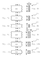
- FIG. 6a, 6b to 11 a, 11 b are sections of the busbars used today or respectively cross sections thereof shown. From the drawing figures it can be seen that of the total of six different busbars three, namely the busbars 22a, 22b and 22c have the same thickness D6 but different widths B6, 87, B8, while the busbars 22d, 22e and 22f have a greater thickness D9 however, are different in their width dimensions B9, B10 and B11, with B9 corresponding to the width B6, B10 to the width B7 and B11 to the width 88.
- busbars made of electrically conductive copper material in cross-section dimensions 30 x 5.20 x 5 and 12 x 5 mm as well as 30 x 10, 20 x 10 and 12 x 10 mm are now available as standard.
- each holding component 20 Since the depressions or partial depressions provided in each holding component 20 are each equal to half the thickness of an associated busbars are dimensioned, it is now clear that by means of a pair of mounted in succession of its corresponding flat side on a substrate support rails 20 total closed on all sides shots for holding the busbars 22a to 22f can be formed.
- the width dimensions of the transverse recesses and partly dash-dotted lines and the associated bus bars are shown, so that the assignment of depressions or recessed sections and busbars is recognizable.
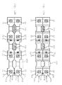
- Fig. 12a and 12b two ways of forming a support assembly from each of a pair of support members 20 can be generated mounting arrangements shown, wherein the mountable in the respective support assembly busbars of different sizes are partially indicated in section and partly dash-dotted lines.
- the graphic representations are self-explanatory, ie it can be seen that by means of a pair of support members 20 according to the Fig. 1 to 5 six busbars with different external dimensions and thus cross - sectional areas, as in the Fig.
- the already mentioned in addition to the mounting holes 26 provided threaded bores 30 may serve for attachment of other attachments, such as electrical flashovers to the housing or leakage currents preventing components.
- This in Fig. 13 shown modified embodiment shows a support member 120, which compared to the in Fig. 1 shown holding member 20 is further developed on the one hand with respect to a possible material-saving cost-effective design in the outer shape.
- the receiving recesses 124a to 124d provided with the additional transverse recesses are in part provided with further additional transverse recesses whose width measured in the longitudinal direction of the support component is smaller and whose depth is greater than the width and depth of the support components 20 provided additional transverse recesses.
- the additional additional transverse recesses 124a for holding in each case a busbar 22e (FIG. Fig. 10a, b ) provided in the in Fig. 15 illustrated manner - in relation to the holder by support members 20 - rotated by 90 ° position upright between two support members 120 are clamped.
- the distances between the busbars provided by the use of the support members 120 additional further transverse recesses 22b increases, so that a higher security against leakage currents or flashovers between the busbars and on the other hand is achieved by the possibility of doubling the number of busbars to be supported 22b improved dissipation of the heat loss in the busbars.
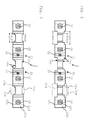
- FIG. 16 to 21 For example, various combinations of two support members 220 are shown, one above the other, forming a support means and between each of which three similar bus bars 22a, 22b, 22c, 22d, 22e, 22f are defined.
- the mounting components 220 have a different shape than the exemplary embodiments of the preceding figures. While the spaced-apart mounting portions 40, in which the mounting holes 26 and the threaded holes 30 are arranged, are configured largely identical to the other embodiments, have the formed on the individual flat sides 20a, 20b, 20c and 20d receiving recesses 224a, 224b, 224c and 224d each have a complex shape and contour.
- each individual busbar 22a, 22b, 22c, 22d, 22e, 22f relative to a above the two support members 220 shown, usually formed by a rear wall or a mounting plate substrate 50 has an identical coincident distance and an identical matching alignment in the longitudinal direction of the support members 220 relative to the associated mounting portion 40.
- busbars 22a, 22b, 22c, 22d, 22e, 22f lie with their lower left corner of the cross-sectional area respectively on a bottom surface of the associated receiving recess 224a, 224b, 224c and 224d and on a stop surface 232a, 232b laterally delimiting the fastening section 40, 232c or 232d on.
- a reference corner 234 can be set, each having the same distance to the substrate 50 and each the same distance relative to the immediately adjacent mounting portion 40 has.
- a plurality of bus bars 22d defined with a cross-sectional area of 30 x 10 mm.
- Fig. 17 instead of having shown a plurality of busbars 22a with a cross-sectional area of 30 ⁇ 5 mm with the same orientation relative to the lower left corner 234 of the cross-sectional areas of the busbars 22d, 22a, respectively Fig. 17
- Support member 220 shown above are tilted about a longitudinal axis 60 by 180 °, so that the opposite flat side 20a facing the lower support member 220 and its upwardly facing flat side 20a.
Landscapes
- Installation Of Bus-Bars (AREA)
Applications Claiming Priority (2)
| Application Number | Priority Date | Filing Date | Title |
|---|---|---|---|
| DE202010002892 | 2010-02-26 | ||
| DE202010004982U DE202010004982U1 (de) | 2010-02-26 | 2010-04-14 | Sammelschienen-Halterungsanordnung |
Publications (2)
| Publication Number | Publication Date |
|---|---|
| EP2362510A2 true EP2362510A2 (fr) | 2011-08-31 |
| EP2362510A3 EP2362510A3 (fr) | 2014-02-26 |
Family
ID=43983957
Family Applications (1)
| Application Number | Title | Priority Date | Filing Date |
|---|---|---|---|
| EP11156059.5A Withdrawn EP2362510A3 (fr) | 2010-02-26 | 2011-02-25 | Agencement de fixation de jeux de barres |
Country Status (2)
| Country | Link |
|---|---|
| EP (1) | EP2362510A3 (fr) |
| DE (1) | DE202010004982U1 (fr) |
Cited By (1)
| Publication number | Priority date | Publication date | Assignee | Title |
|---|---|---|---|---|
| ITUA20163940A1 (it) * | 2016-05-30 | 2017-11-30 | Pizzato Elettrica Srl | Interruttore di sicurezza per il controllo di accessi |
Citations (1)
| Publication number | Priority date | Publication date | Assignee | Title |
|---|---|---|---|---|
| DE19511358A1 (de) | 1995-03-28 | 1996-10-02 | Kloeckner Moeller Gmbh | Stromschienenträger für Niederspannungs-Energieverteiler |
Family Cites Families (7)
| Publication number | Priority date | Publication date | Assignee | Title |
|---|---|---|---|---|
| FR901075A (fr) * | 1943-12-22 | 1945-07-17 | Gardy Particip App | Dispositif de support d'au moins une barre omnibus |
| FR1559497A (fr) * | 1967-04-13 | 1969-03-07 | ||
| JPS5337857Y2 (fr) * | 1975-06-23 | 1978-09-13 | ||
| DE3013845A1 (de) * | 1980-04-10 | 1981-10-15 | Brown, Boveri & Cie Ag, 6800 Mannheim | Stromschienentraeger fuer zwei querschnitte bei gleicher kontaktebene |
| FR2579006B1 (fr) * | 1985-03-14 | 1987-07-10 | Alsthom Cgee | Support de barre electrique |
| ITBG20060035A1 (it) * | 2006-07-06 | 2008-01-07 | Abb Service Srl | Elemento di isolamento di barre conduttrici e dispositivo di isolamento e supporto di barre conduttrici comprendente tale elemento. |
| JP2008104256A (ja) * | 2006-10-17 | 2008-05-01 | Chiyuuritsu Denki Kk | 支持台 |
-
2010
- 2010-04-14 DE DE202010004982U patent/DE202010004982U1/de not_active Expired - Lifetime
-
2011
- 2011-02-25 EP EP11156059.5A patent/EP2362510A3/fr not_active Withdrawn
Patent Citations (1)
| Publication number | Priority date | Publication date | Assignee | Title |
|---|---|---|---|---|
| DE19511358A1 (de) | 1995-03-28 | 1996-10-02 | Kloeckner Moeller Gmbh | Stromschienenträger für Niederspannungs-Energieverteiler |
Cited By (3)
| Publication number | Priority date | Publication date | Assignee | Title |
|---|---|---|---|---|
| ITUA20163940A1 (it) * | 2016-05-30 | 2017-11-30 | Pizzato Elettrica Srl | Interruttore di sicurezza per il controllo di accessi |
| WO2017208124A1 (fr) * | 2016-05-30 | 2017-12-07 | Pizzato Elettrica S.R.L. | Interrupteur de sécurité pour contrôle d'accès |
| CN109314009A (zh) * | 2016-05-30 | 2019-02-05 | 彼扎特电气有限公司 | 用于通道控制的安全开关 |
Also Published As
| Publication number | Publication date |
|---|---|
| DE202010004982U1 (de) | 2011-11-02 |
| EP2362510A3 (fr) | 2014-02-26 |
Similar Documents
| Publication | Publication Date | Title |
|---|---|---|
| EP1117162B1 (fr) | Système de barres omnibus et ensemble de connexions pour connecter les barres aux bornes d'un appareil d'installation | |
| DE69511156T2 (de) | Sammelschienenanordnung, insbesondere für eine Energieverteilungsschrank | |
| EP3446381B1 (fr) | Agencement permettant la connexion sans risque de contact d'un système de rails collecteurs de courant | |
| EP2911253B1 (fr) | Adaptateur de barre collectrice et système constitué de barres collectrices et d'un adaptateur de barre collectrice | |
| DE69905932T2 (de) | Stromschiene für eine elektrische energieverteilung | |
| EP2559107B1 (fr) | Borne de connexion de conducteur principal | |
| EP0727797B1 (fr) | Interrupteur de sécurité | |
| DE102006022374A1 (de) | Schaltgerät, insbesondere Sicherungslasttrennschalter | |
| EP1710884A1 (fr) | Système de bus à deux phases ou multiphases laminés | |
| DE19530659C1 (de) | Niederspannungs-Sammelschienensystem | |
| EP0221839A2 (fr) | Interrupteur de puissance comportant un boîtier isolant à ouverture frontale et une plaquette de circuit | |
| EP2037550B1 (fr) | Protection contre le contact pour un rail | |
| EP0466043A2 (fr) | Installation de distribution comprenant au moins deux rangées d'appareils électriques de type étroit | |
| EP3016215A1 (fr) | Dispositif de mise a la terre de rails | |
| EP0223732A1 (fr) | Disjoncteur multipolaire de puissance basse tension avec barres de courant | |
| WO2008003680A1 (fr) | Support de barres conductrices et unité distributrice de courant dotée d'un support de barres conductrices | |
| EP1137137A1 (fr) | Adaptateur pour une armoire électrique | |
| DE29706564U1 (de) | Trageinrichtung für Stromschienen | |
| EP1251537B1 (fr) | Disjoncteur-sectionneur à fusibles du type baguette | |
| EP1253610B1 (fr) | Adaptateur pour contacter des sectionneurs de coupure en charge sur barres omnibus | |
| DE69904504T2 (de) | Busschienenverbindungsstruktur | |
| WO2007033946A1 (fr) | Ensemble barre collectrice pour une installation de distribution electrique | |
| EP0180206A2 (fr) | Bloc de barres omnibus | |
| DE202010004982U1 (de) | Sammelschienen-Halterungsanordnung | |
| EP2362506A2 (fr) | Dispositif de limitation d'arc électrique |
Legal Events
| Date | Code | Title | Description |
|---|---|---|---|
| PUAI | Public reference made under article 153(3) epc to a published international application that has entered the european phase |
Free format text: ORIGINAL CODE: 0009012 |
|
| AK | Designated contracting states |
Kind code of ref document: A2 Designated state(s): AL AT BE BG CH CY CZ DE DK EE ES FI FR GB GR HR HU IE IS IT LI LT LU LV MC MK MT NL NO PL PT RO RS SE SI SK SM TR |
|
| AX | Request for extension of the european patent |
Extension state: BA ME |
|
| RIC1 | Information provided on ipc code assigned before grant |
Ipc: H02G 5/02 20060101AFI20131004BHEP |
|
| PUAL | Search report despatched |
Free format text: ORIGINAL CODE: 0009013 |
|
| AK | Designated contracting states |
Kind code of ref document: A3 Designated state(s): AL AT BE BG CH CY CZ DE DK EE ES FI FR GB GR HR HU IE IS IT LI LT LU LV MC MK MT NL NO PL PT RO RS SE SI SK SM TR |
|
| AX | Request for extension of the european patent |
Extension state: BA ME |
|
| RIC1 | Information provided on ipc code assigned before grant |
Ipc: H02G 5/02 20060101AFI20140123BHEP |
|
| STAA | Information on the status of an ep patent application or granted ep patent |
Free format text: STATUS: THE APPLICATION IS DEEMED TO BE WITHDRAWN |
|
| 18D | Application deemed to be withdrawn |
Effective date: 20140827 |