EP2363213B1 - Outil de nettoyage de tuyau pour un système à spirale de nettoyage de tuyau - Google Patents
Outil de nettoyage de tuyau pour un système à spirale de nettoyage de tuyau Download PDFInfo
- Publication number
- EP2363213B1 EP2363213B1 EP11150830.5A EP11150830A EP2363213B1 EP 2363213 B1 EP2363213 B1 EP 2363213B1 EP 11150830 A EP11150830 A EP 11150830A EP 2363213 B1 EP2363213 B1 EP 2363213B1
- Authority
- EP
- European Patent Office
- Prior art keywords
- pipe cleaning
- spiral
- cleaning tool
- core
- bristles
- Prior art date
- Legal status (The legal status is an assumption and is not a legal conclusion. Google has not performed a legal analysis and makes no representation as to the accuracy of the status listed.)
- Not-in-force
Links
- 238000004140 cleaning Methods 0.000 title claims description 219
- 230000008878 coupling Effects 0.000 claims description 48
- 238000010168 coupling process Methods 0.000 claims description 48
- 238000005859 coupling reaction Methods 0.000 claims description 48
- 230000001680 brushing effect Effects 0.000 claims description 5
- 238000005520 cutting process Methods 0.000 claims description 5
- 238000003801 milling Methods 0.000 claims description 5
- 238000005553 drilling Methods 0.000 claims description 3
- 239000011162 core material Substances 0.000 description 96
- 239000000463 material Substances 0.000 description 8
- 239000002184 metal Substances 0.000 description 7
- 229910052751 metal Inorganic materials 0.000 description 7
- 230000000694 effects Effects 0.000 description 6
- 239000012535 impurity Substances 0.000 description 6
- 239000004033 plastic Substances 0.000 description 6
- 230000007423 decrease Effects 0.000 description 4
- 238000004519 manufacturing process Methods 0.000 description 4
- 239000011343 solid material Substances 0.000 description 4
- 229910001369 Brass Inorganic materials 0.000 description 3
- 229910000831 Steel Inorganic materials 0.000 description 3
- 239000010951 brass Substances 0.000 description 3
- 239000002131 composite material Substances 0.000 description 3
- 239000000356 contaminant Substances 0.000 description 3
- 238000011109 contamination Methods 0.000 description 3
- 239000010959 steel Substances 0.000 description 3
- 238000006073 displacement reaction Methods 0.000 description 2
- 238000003780 insertion Methods 0.000 description 2
- 230000037431 insertion Effects 0.000 description 2
- 238000000034 method Methods 0.000 description 2
- 229910001220 stainless steel Inorganic materials 0.000 description 2
- 239000010935 stainless steel Substances 0.000 description 2
- 229910001018 Cast iron Inorganic materials 0.000 description 1
- 206010010774 Constipation Diseases 0.000 description 1
- RYGMFSIKBFXOCR-UHFFFAOYSA-N Copper Chemical compound [Cu] RYGMFSIKBFXOCR-UHFFFAOYSA-N 0.000 description 1
- 241001315609 Pittosporum crassifolium Species 0.000 description 1
- 230000000295 complement effect Effects 0.000 description 1
- 150000001875 compounds Chemical class 0.000 description 1
- 229910052802 copper Inorganic materials 0.000 description 1
- 239000010949 copper Substances 0.000 description 1
- 230000008030 elimination Effects 0.000 description 1
- 238000003379 elimination reaction Methods 0.000 description 1
- 230000002349 favourable effect Effects 0.000 description 1
- 238000011086 high cleaning Methods 0.000 description 1
- 239000011796 hollow space material Substances 0.000 description 1
- 239000011133 lead Substances 0.000 description 1
- 239000002245 particle Substances 0.000 description 1
- 238000005498 polishing Methods 0.000 description 1
- 238000005476 soldering Methods 0.000 description 1
- 239000007787 solid Substances 0.000 description 1
- 229910052572 stoneware Inorganic materials 0.000 description 1
- 239000000126 substance Substances 0.000 description 1
- 238000003466 welding Methods 0.000 description 1
Images


Classifications
-
- B—PERFORMING OPERATIONS; TRANSPORTING
- B08—CLEANING
- B08B—CLEANING IN GENERAL; PREVENTION OF FOULING IN GENERAL
- B08B9/00—Cleaning hollow articles by methods or apparatus specially adapted thereto
- B08B9/02—Cleaning pipes or tubes or systems of pipes or tubes
- B08B9/027—Cleaning the internal surfaces; Removal of blockages
- B08B9/04—Cleaning the internal surfaces; Removal of blockages using cleaning devices introduced into and moved along the pipes
- B08B9/043—Cleaning the internal surfaces; Removal of blockages using cleaning devices introduced into and moved along the pipes moved by externally powered mechanical linkage, e.g. pushed or drawn through the pipes
- B08B9/045—Cleaning the internal surfaces; Removal of blockages using cleaning devices introduced into and moved along the pipes moved by externally powered mechanical linkage, e.g. pushed or drawn through the pipes the cleaning devices being rotated while moved, e.g. flexible rotating shaft or "snake"
-
- A—HUMAN NECESSITIES
- A46—BRUSHWARE
- A46B—BRUSHES
- A46B13/00—Brushes with driven brush bodies or carriers
- A46B13/001—Cylindrical or annular brush bodies
- A46B13/006—Cylindrical or annular brush bodies formed by winding a strip tuft in a helix about the body
-
- A—HUMAN NECESSITIES
- A46—BRUSHWARE
- A46B—BRUSHES
- A46B13/00—Brushes with driven brush bodies or carriers
- A46B13/02—Brushes with driven brush bodies or carriers power-driven carriers
-
- A—HUMAN NECESSITIES
- A46—BRUSHWARE
- A46B—BRUSHES
- A46B3/00—Brushes characterised by the way in which the bristles are fixed or joined in or on the brush body or carrier
- A46B3/18—Brushes characterised by the way in which the bristles are fixed or joined in or on the brush body or carrier the bristles being fixed on or between belts or wires
-
- A—HUMAN NECESSITIES
- A46—BRUSHWARE
- A46B—BRUSHES
- A46B9/00—Arrangements of the bristles in the brush body
- A46B9/02—Position or arrangement of bristles in relation to surface of the brush body, e.g. inclined, in rows, in groups
-
- B—PERFORMING OPERATIONS; TRANSPORTING
- B08—CLEANING
- B08B—CLEANING IN GENERAL; PREVENTION OF FOULING IN GENERAL
- B08B9/00—Cleaning hollow articles by methods or apparatus specially adapted thereto
- B08B9/02—Cleaning pipes or tubes or systems of pipes or tubes
- B08B9/027—Cleaning the internal surfaces; Removal of blockages
- B08B9/04—Cleaning the internal surfaces; Removal of blockages using cleaning devices introduced into and moved along the pipes
- B08B9/043—Cleaning the internal surfaces; Removal of blockages using cleaning devices introduced into and moved along the pipes moved by externally powered mechanical linkage, e.g. pushed or drawn through the pipes
- B08B9/0436—Cleaning the internal surfaces; Removal of blockages using cleaning devices introduced into and moved along the pipes moved by externally powered mechanical linkage, e.g. pushed or drawn through the pipes provided with mechanical cleaning tools, e.g. scrapers, with or without additional fluid jets
-
- E—FIXED CONSTRUCTIONS
- E03—WATER SUPPLY; SEWERAGE
- E03C—DOMESTIC PLUMBING INSTALLATIONS FOR FRESH WATER OR WASTE WATER; SINKS
- E03C1/00—Domestic plumbing installations for fresh water or waste water; Sinks
- E03C1/12—Plumbing installations for waste water; Basins or fountains connected thereto; Sinks
- E03C1/30—Devices to facilitate removing of obstructions in waste-pipes or sinks
- E03C1/302—Devices to facilitate removing of obstructions in waste-pipes or sinks using devices moved through the pipes
-
- E—FIXED CONSTRUCTIONS
- E03—WATER SUPPLY; SEWERAGE
- E03F—SEWERS; CESSPOOLS
- E03F9/00—Arrangements or fixed installations methods or devices for cleaning or clearing sewer pipes, e.g. by flushing
- E03F9/002—Cleaning sewer pipes by mechanical means
- E03F9/005—Apparatus for simultaneously pushing and rotating a cleaning device carried by the leading end of a cable or an assembly of rods
-
- A—HUMAN NECESSITIES
- A46—BRUSHWARE
- A46B—BRUSHES
- A46B2200/00—Brushes characterized by their functions, uses or applications
- A46B2200/30—Brushes for cleaning or polishing
- A46B2200/3013—Brushes for cleaning the inside or the outside of tubes
Definitions
- the invention relates to a pipe cleaning tool for a pipe cleaning spiral system according to the preamble of claim 1.
- Contaminations and blockages in channels and pipes are a known problem in that they can affect or even obstruct flow. Depending on the severity of constipation different cleaning methods are known.
- a pipe cleaning spiral system comprises a pipe cleaning spiral with a diameter of 8 mm to 32 mm, which is driven at its one end by a rotary-push device. This can be done both manually and by machine.
- a pipe cleaning tool is provided, is processed with the impurities or the cause of the blockage in the pipe or channel.
- the pipe cleaning tools used today are usually, depending on the nature of the blockage and depending on the nature of the pipe, designed as a milling cutter, drill, cutting head or chain, so that even very strong, coarse blockages, deposits and contaminants in pipes and channels can be eliminated.
- the patent US 3,757,375 describes a device for extracting obstructions from a constriction, the device comprising an outer elastic shaft that is movable relative to an inner element. Grippers are arranged on the inner element which, as the outer shaft moves toward the inner element, are moved radially outwardly to grasp the obstruction, so that the obstruction can be detected by the grippers and then removed by retracting the device.
- the patent GB 975,067 relates to a pipe cleaning tool having a connection means for connecting to a pipe cleaning spiral displaceable in a rotational and pushing movement.
- a rotatable and resilient coil having a plurality of axially spaced and transversely extending beyond the diameter of the spiral discs, each having a radial slot and which are held by an elastic wire or rod, which is axially to the spiral and extends through the discs in the middle.
- the axially spaced discs or their slots provide axially spaced leading edges for guiding and removing the obstruction.
- the font GB 362,614 relates to a device for cleaning, peeling or polishing pipes in the form of a driven shaft, the a plurality of this radially outwardly and parallel with this extending stripping elements.
- the document US 5,813,089 describes a cleaning device in which a brush is driven by a motor via a shaft.
- the publication EP 0 456 402 A1 describes a generic tube cleaning tool for a pipe cleaning spiral system, wherein the pipe cleaning tool is brush-like for brushing and cleaning pipes and has a plurality of radially extending bristles disposed about an axial extent and circumferentially of the pipe cleaning tool, the pipe cleaning tool at least one connecting means for connecting comprising at least one displaceable in a rotational and pushing movement pipe cleaning spiral.
- the document GB 691,105 describes a device for cleaning the inner surface of tubes, wherein the device comprises a plurality of chain-like coupled elements, on each of which radially outwardly cleaning bristles extend.
- the invention has for its object to provide a pipe cleaning tool for a pipe cleaning spiral system, which improves the cleaning effect compared to known pipe cleaning tools and at least partially solves the problems mentioned.
- the invention solves the known problems with a pipe cleaning tool for pipe cleaning spiral systems with the features of claim 1.
- the pipe cleaning tool comprises at least one connecting device for connecting to at least one pipe cleaning spiral.
- the pipe cleaning tool is brush-shaped for brushing and cleaning pipes and has a plurality of radially extending bristles extending over an axial extent and circumferentially of the pipe cleaning tool are arranged.
- the pipe cleaning tool has at least one connecting device for connecting to at least one displaceable in a rotational and pushing movement pipe cleaning spiral of the pipe cleaning spiral system.
- the pipe cleaning tool according to the invention is characterized in that it comprises at least one spiral section, wherein at one axial end of the spiral section, the connecting means is arranged, and the bristles are fixed to a core, which is arranged in the interior of the spiral of the at least one spiral section, and the plurality of bristles in the spiral section extend outwardly from the core from the interior of the spiral of the spiral section between adjacent spiral helices beyond the spiral section.
- the pipe cleaning tool according to the invention allows a significantly better cleaning effect than known pipe cleaning tools, since the radially extending bristles, when the tool is rotated or pushed, it can remove contaminants very effectively and completely.
- the tube cleaning tool has high elasticity and flexibility with high robustness, similar to tube cleaning coils themselves, whereby the tool according to the invention can be integrated very well into conventional tube cleaning spiral systems.
- the bristles may be attached in the spiral section, for example, to its spiral itself.
- the bristles may be connected inside the spiral and extend radially outwardly therebetween between adjacent spiral coils.
- the bristles can be made for example of plastic, metal or a composite material.
- a different manufacturing process for the pipe cleaning tool can be used, which for example for the price, the robustness and the dimensions of the tool can be crucial.
- the bristle material can be chosen so that optimum cleaning can be carried out without damaging the pipe.
- the bristles in addition to a radial extent, also have an axial extent, and can vary the length of the axial and radial extensions in the direction of the axis of the tube cleaning tool, depending on the desired action and field of application.
- Such bristles which extend radially outward perpendicular to the axis of the tool, can yield less easily in their radial extent than bristles which also have an axial extension. If the bristles also have an axial extension in addition to a radial extension, the bristles yield more easily with a force acting perpendicular to the axis, thus enabling a more gentle cleaning.
- the real or imaginary axis of the pipe cleaning tool does not have to be rigidly provided, but may also be bendable or bendable at least in sections. Thereby, for example, insertion into pipes can be facilitated, the tool can follow pipe bends more easily, and at a high rotational speed, in pipe cleaning tools where the radial extent of the bristles is smaller than the pipe diameter, at least a portion of the bristles may contact the pipe by centrifugal force Pass pipe inner wall.
- the core to which the bristles are fastened, can be formed by a plurality of, in particular two, twisted metal wires extending in the axial direction, between which the bristles are interlaced and from which the bristles extend radially outwardly beyond the circumference of the core receiving coil of the at least one spiral section.
- the bristles may be twisted together to form a core.
- the core may for example consist of a solid material or hollow material, such as plastic or metal, in which the bristles are encapsulated or overmolded.
- other attachment options of the bristles may be provided on the core, for example, the bristles may be braided around a solid core material.
- the core may for example be rigid, elastic or flexible.
- the core has a cylindrical shape with a round or polygonal cross-section or has a structure on the surface.
- a structure on the surface may, for example, result from the attachment of the bristles or be advantageous for fastening the bristles.
- the spiral of the spiral section may advantageously be cylindrical, so that the spiral has the shape of a cylinder spiral.
- the spiral may take the form of commercial pipe cleaning spirals or comprise a portion of such.
- the core of the pipe cleaning tool to which bristles are fastened comprises at least two core elements, in particular axially arranged in series and preferably mechanically coupled.
- the number and length of the core elements can be chosen in terms of scope and task.
- Such a designed pipe cleaning tool is variable in terms of Movements and deflections perpendicular to its axis, since the core is not formed in one piece and thus less stiff.
- the core elements may abut each other or be spaced apart.
- intermediate elements may be provided between the core elements and also at least partially connected to them, in particular form-fitting, non-positive or cohesive.
- the core elements may be interconnected by the intermediate elements. This can be done, for example, by attaching, such as soldering, welding or clamping of intermediate elements, such as small spirals or wires to the core elements.
- the core elements are only slightly spaced apart, whereby a very high cleaning performance is ensured.
- axial forces resulting from the use of the pipe cleaning tool on the core elements can be absorbed by the boundaries.
- the core having the core elements is guided by the spiral, within which it is arranged, a high stability is ensured in addition to the increased radial flexibility.
- a high stability is ensured in addition to the increased radial flexibility.
- the pipe cleaning tool can follow the pipe run better in pipe bends, which more bristles can rest against the inner wall of a pipe. As a result, a particularly good cleaning effect can be generated.
- adjacent core elements are mechanically coupled to each other by articulations.
- articulations for example, a better stability, cleaning effect and / or handling of the pipe cleaning tool can be ensured.
- the articulated joints are designed so that the axes of adjacent core elements are tilted against each other, so that the pipe cleaning tool can be deflected within the spiral section or adjacent thereto perpendicular to its axis in rest position.
- This can be ensured, for example, by the hinge connections between the adjacent core elements providing at least one axis of rotation which is not parallel to the axis of the core elements.
- the joint connections can also be designed so that they allow a tilting of adjacent core elements and at the same time make a rotation of the core elements against each other impossible by the joints provide corresponding axes of rotation. This can be advantageous, in particular, if it is intended to ensure a constant rotational speed of the bristles over the axial extent of the tool.
- connections between two axially adjacent core elements are formed so that they can absorb tensile and compressive forces even when rotated against each other or even rotating core elements.
- This allows a stable behavior of the pipe cleaning tool even with a Push or pull movement with simultaneous rotation of the tool, and thus possibly at least partially the core elements, can be achieved, which is of particular importance for the practical application of the tool.
- a connection can be realized as a ball / socket joint or other conventional joint connections, such as a hinge joint, a saddle joint, a pivot joint or joint combinations.
- the at least one connecting device of the pipe cleaning tool is designed as an actuatable coupling which can be actuated by means of a tool or without tools.
- a very quick and easy coupling is possible, for example, a pipe cleaning spiral.
- conventional couplings such as KaRo®, Rioned® or T-slot couplings can be provided.
- the pipe cleaning tool can be used in all commercial pipe cleaning spiral systems.
- the bristles are arranged in an axial section, at the two axial ends of each of which a connecting device is arranged.
- the connecting device may in particular also be a clutch.
- the pipe cleaning tool may comprise a spiral section, at the two axial ends of which a connecting device, in particular a coupling, is provided, wherein the bristles are fastened to a core which is located inside the spiral of the spiral section lies.
- a connecting device in particular a coupling
- At least one connecting device in particular a coupling, can abut against one end face of the core, that is to say one axial end of the core to which the bristles are fastened, whereby a frictional connection between the at least one connecting device and the core can result. This ensures even better stability of the pipe cleaning tool.
- both connecting devices in particular both couplings, with the core to which the bristles are attached, positively or materially connected.
- the pipe cleaning tool has a particularly high strength and robustness.
- the length of the radial extent of the bristles varies in the axial direction of the pipe cleaning tool.
- the frictional force of the pipe cleaning tool on the impurities in advancing the pipe cleaning tool can be varied in a pipe with a partially clogged cross-section.
- the length of the radial extent of the bristles may increase or decrease from one axial end of the tube cleaning tool to the other axial end.
- other axial courses of the radial extent of the bristles may also be advantageous.
- further axial courses are advantageous, which support a removal of dissolved impurities, such as particles.
- the invention comprises a pipe cleaning spiral system which comprises at least one pipe cleaning spiral and at least one brush-type pipe cleaning tool according to the invention.
- the pipe cleaning spiral system according to the invention combines the advantages of commercially available pipe cleaning spiral systems with the stated advantages of the pipe cleaning tool according to the invention.
- the pipe cleaning spiral system is designed so that at the two axial ends of the pipe cleaning tool in each case a connecting device, in particular a clutch is arranged, wherein the pipe cleaning tool at one axial end with a pipe cleaning spiral and at the other axial end with another pipe cleaning tool, in particular with a Drill, Milling, cutting or chain slinging tool is connected.
- a connecting device in particular a clutch
- the pipe cleaning tool at one axial end with a pipe cleaning spiral and at the other axial end with another pipe cleaning tool, in particular with a Drill, Milling, cutting or chain slinging tool is connected.
- the brush-type pipe cleaning tool according to the invention and the additional pipe cleaning tool can thus be installed independently of one another into the pipe cleaning spiral system according to the invention via the connecting devices or removed from the system become.
- the individual pipe cleaning tools can be replaced separately depending on the individual state of wear.
- the pipe cleaning system according to the invention can also be configured so that between the brush-like pipe cleaning tool according to the invention and the other pipe cleaning tool and a further spiral section can be arranged.
- a plurality of pipe cleaning tools, possibly spaced apart from one another by spiral sections, can also be arranged one behind the other in the axial direction. It can be particularly advantageous if all connecting devices are designed as uniform, commercially available couplings. As a result, the individual pipe cleaning tools can be interchanged arbitrarily, and the pipe cleaning system according to the invention can be combined with all on the market pipe cleaning systems.
- the pipe cleaning system according to the invention comprises a motor drive device for rotating the at least one pipe cleaning spiral and the at least one pipe cleaning tool.
- the thrust can be ensured either manually or by another or the same machine device.
- the machine device may be a commercially available drum spiral machine.
- the connecting means in particular the couplings of the individual elements of the pipe cleaning spiral system are designed so that they are loaded in the direction of rotation with a torque, positively or non-positively. This ensures that the application of a torque at one end of the pipe cleaning spiral system is substantially uniform Rotation of the entire system causes.
- the pipe cleaning tools or systems according to the invention described below are particularly suitable for brushing and cleaning drain pipes in the home or in the private sector, in which the spiral systems used conventionally have a diameter between 8 mm and 32 mm. Those skilled in the art will recognize that the invention is not limited to such dimensions or uses, and in particular may be applied to the industrial sector with spiral systems which may have a much larger or smaller diameter.
- the pipe cleaning tools according to the invention are particularly suitable for use in all commercially available via a motor or manually driven pipe cleaning spiral systems.
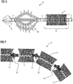
- a core 3 is shown, are braided in the bristles 4, said core 3 can be added to the design of a pipe cleaning tool according to the invention, for example, from a spiral section, which will be discussed in more detail below.
- Spiral sections of the tools according to the invention are often made of stainless steel because of their chemical and mechanical properties, but depending on the application, other suitable materials made of metal, especially brass or steel, plastic or composite can be used.
- the bristle material may comprise or consist of plastic, brass, steel, stainless steel or another metal. Accordingly, the tools according to the invention are suitable for use in all commercial pipes and sewer pipes, which are made for example of plastic, steel, copper, brass, lead, cast iron or stoneware.
- the core 3 according to Fig. 1 can be made from either a single bent wire or several individual wires twisted together.
- the bristles 4 are woven into the wire structure of the core 3 so as to be fixedly connected to the core 3.
- both the bristles 4 and the or the wires may be made of suitable materials such as metal, plastic or a composite material. It is clear that the radial extent of the bristles 4 extends radially far beyond the radial extent of the core 3.
- the core 3 is not completely rigid in the illustrated embodiment but elastically deformable, so that it can follow tube bends in use.
- Fig. 2 is a core 3 made of a solid material, are fixed to the bristles 4, shown with a coupling 2.
- the bristles 4 are cast in the core 3 of solid material, and the core 3 has the shape of a cylinder.
- core 3 is material or form-fitting connection means such as a clutch 2 arranged at an axial end.
- the term "coupling” is used for coupling elements, wherein a releasable mechanical connection device is provided by coupling two complementary designed coupling elements.
- the in Fig. 2 shown core 3 for example, be arranged by means of its coupling 2 to a corresponding coupling 2 within a pipe cleaning spiral section 6.
- the core shown does not always have to have the coupling shown. Instead, no coupling or coupling elements can be provided at both ends of the core, in this embodiment, the core is disposed within a spiral 5 of a spiral section 6 of a pipe cleaning tool 1 according to the invention.
- a pipe cleaning spiral 5 can be fastened to the core 3 itself.
- the in Fig. 2 shown core 3 in providing suitable coupling or coupling elements at the two ends as a core element 11, 11 'of an in Fig. 7
- a coupling 2 at each end of the in Fig. 2 core are provided.
- the coupling 2 may, for example, by type of in Fig. 7 be shown articulated connection 12 may be formed. This will be discussed in more detail below.
- Fig. 2 illustrated component of a pipe cleaning tool 1 according to the invention is very robust and particularly suitable as part of a pipe cleaning tool 1 for the cleaning of very hard contaminants.
- a spiral section 6 is shown as part of an inventively designed pipe cleaning tool 1, at its two axial ends in each case a coupling 2, in particular for coupling to a pipe cleaning spiral or to a drill is arranged.
- a cylindrical spiral 5 at the axial ends of which couplings are mounted, wherein in a connecting portion between coil 2 and spiral 5, the helices of the spiral 5 are increasingly close, whereby a very good grip of the clutches 2 can be ensured on the coil 5.
- core may be received radially inward in the spiral, wherein the bristles extend radially beyond the spiral portion.
- the in Fig. 2 illustrated coupling 2 omitted. It is understood that the respective dimensions of the spiral portion 6 for receiving the in the Figures 1 and 2 shown cores must be adapted. In this respect, the representations are not to scale.
- Fig. 3 represented part of a pipe cleaning tool according to the invention
- the couplings 2 in a conventional manner radial projections, which allow the mechanical turning of the spiral helix to the respective coupling in the manufacture of the tool according to the invention.
- All tools according to the invention which have a spiral section like the one in Fig. 3 have shown, may have at least one such coupling.
- the coupling or the coupling elements are designed so that in the usual forces occurring during operation of the pipe cleaning system, the coupling connection with the associated spiral section does not solve unintentionally.
- a pipe cleaning tool 1 with a spiral portion 6 of a spiral 5, a core 3, bristles 4 and two clutches 2 is shown. It can be produced, for example, that in the arrangement according to Fig. 3 before turning the second clutch on the second axial end of the spiral 5, a core 3 according to Fig. 1 is inserted into the interior of the spiral 5. The attachment of the couplings 2 to the spiral 5 is so far with the Fig. 3 identical. Within the spiral 5, the core 3 is arranged, are attached to the bristles 4. The bristles 4 thus extend radially outward within the spaces 7 between the helical coils. The radial extent of the bristles goes far beyond the radial extent of the spiral 5 addition.
- a spiral 5 with a diameter of 32 mm starting from the spiral axis to provide a radial extension of the bristles 4 of about 115 mm.
- a pipe cleaning tool 1 can be used for example in pipes with a diameter of about 125 mm to 150 mm. It may also be advantageous to provide a radial extension of the bristles 4 of 25 mm to 35 mm in the case of a spiral 5 with a diameter of 16 mm. Corresponding to the radial extent of the bristles 4 and the working objective, such a pipe cleaning tool 1 may be suitable for pipes of 30 mm to 70 mm.
- the core 3 is in the described embodiment with the two couplings 2 in positive engagement, so that no axial displacement of the core 3 in the pipe cleaning tool 1 is possible.
- This in Fig. 4 illustrated pipe cleaning tool 1 can be very easily integrated into pipe cleaning spiral 8, is close to the ground and has both an excellent robustness and good flexibility. Due to the possible use of commercially available pipe cleaning spirals as a spiral 5 in the manufacture of the pipe cleaning tool 1, a very cost-effective production of the pipe cleaning tool 1 according to the invention is possible.
- a pipe cleaning spiral system 8 is shown in fragmentary form, which comprises a brush-type pipe cleaning tool 1 according to the invention and a pipe cleaning tool, which is connected thereto and designed as a cross-blade drill 9.
- the brush-like pipe cleaning tool 1 has at both axial ends in each case a coupling 2, on. At the one axial end, for example, one or more successively coupled pipe cleaning spiral are coupled, wherein the last of the pipe cleaning spirals is coupled to a motor drive (not shown). At the other axial end designed as a cross-blade drill 9 pipe cleaning tool is coupled.
- the brush-type pipe cleaning tool 1 comprises a core 3 with bristles 4 attached thereto and a spiral 5.
- the radial extent of the bristles 4 varies in the axial direction in the illustrated embodiment. Seen from one axial end of the pipe cleaning tool 1, the radial extension of the bristles 4 initially increases, is then constant over an axial section and decreases toward the other axial end. This embodiment is advantageous because it blockages and excessive rotational resistance can be avoided.
- Fig. 6 is shown in section a pipe cleaning spiral system 8, which comprises a brush-like pipe cleaning tool 1, designed as a cross-blade drill 9 pipe cleaning tool and designed as a chain slinger 10 pipe cleaning tool.
- the individual pipe cleaning tools 1, 9, 10 are each coupled with couplings 2 one behind the other.
- the length of the radial extent of the bristles 4 is constant over the axial extent of the brush portion.
- the illustrated pipe cleaning system 8 allows for very many combinations of pipe cleaning tools 1, 9, 10 or others.
- the pipe cleaning tools 1, 9, 10 can be exchanged as desired, with both the respective wear and the respective application can be considered. It may be particularly useful to use uniform, commercial couplings, as this facilitates the replacement of the individual elements of the system and the coupling to commercially available systems and devices.
- the pipe cleaning spiral system 8 comprises, for example, a motor device which sets one or more pipe cleaning spirals and tools arranged serially one behind another in a rotational and / or forward movement
- the cross drill 9 initially removes very coarse blockages in the center of the pipe to be cleaned in the illustrated arrangement
- the chain slinger 10 radially outer deposits and the brush-like pipe cleaning tool 1 and small deposits, especially on the inner wall of the pipe to be cleaned. It is obvious that by means of the pipe cleaning spiral system 8 according to the invention an efficient removal of blockages and at the same time a very good cleaning of pipes and channels can be achieved.
- Fig. 7 is a section of a core 3 of a pipe cleaning tool according to the invention 1 with core elements 11, 11 ', 11 "and respective articulated joints 12 shown, as it is similar to the design of a pipe cleaning tool in the Fig. 4, 5 and 6 can be used by being arranged in the interior of a spiral section and bristles extend radially outward beyond the spiral.
- the radial and axial dimensions of the in Fig. 7 Kerns 3 shown in the section are matched to the dimensions of this core receiving spiral section, so that the in Fig. 7 shown core 3 in turn can be received by a spiral section 6, wherein the bristles 4 extend radially beyond the spiral for the design of a pipe cleaning tool according to the invention in the manner of a Fig. 4, 5 and 6 shown.
- bristles 4 which extend radially outward from the axis of the core elements, are constructed identically and formed in the form of a twisted metal wire. braided, and adjacent core elements 11 ', 11 "are mechanically coupled to one another via articulated connections 12.
- the articulated connections are designed as a ball / socket joint, as a result of which the axes of adjacent core elements 11 ', 11" can be tilted relative to one another.
- the joints 12 are still kar- and pressure loadable, so that a very robust and simultaneously flexible pipe cleaning tool 1 is realized with a correspondingly constructed core 3.
- the articulated connections 12 can be constructed, for example, as at least one, advantageously a plurality of rotary axis joints arranged one behind the other in another embodiment, not shown. As a result, for example, a rotation of adjacent Kernelmente 11 ', 11 "are completely prevented while ensuring flexibility of the core 3 and thus the pipe cleaning tool in a direction perpendicular to its axis.
- core elements 11, 11 ', 11 "and / or articulated connections 12 between the core elements may be designed differently, so that possibly special requirements for a pipe cleaning tool 1 can be taken into account.
Landscapes
- Engineering & Computer Science (AREA)
- Mechanical Engineering (AREA)
- Health & Medical Sciences (AREA)
- Life Sciences & Earth Sciences (AREA)
- Hydrology & Water Resources (AREA)
- Public Health (AREA)
- Water Supply & Treatment (AREA)
- Environmental & Geological Engineering (AREA)
- Cleaning In General (AREA)
Claims (13)
- Outil de nettoyage de tuyau (1) pour un système à spirale de nettoyage de tuyau (8), dans lequel ledit outil de nettoyage de tuyau (1) est réalisé sous la forme de brosse pour brosser et nettoyer des tuyaux et comporte une pluralité de poils (4) s'étendant radialement et étant disposés sur une étendue axiale et circonférentiellement de l'outil de nettoyage de tuyau et ledit outil de nettoyage de tuyau comportant au moins un connecteur pour la connexion à au moins une spirale de nettoyage de tuyau du système à spirale de nettoyage de tuyau (8), spirale qui peut être mise en rotation et en translation, caractérisé en ce que l'outil de nettoyage de tuyau (1) comporte au moins une partie en spirale (6), ledit connecteur étant disposé à une extrémité axiale de la partie en spirale et les poils (4) étant fixés à un noyau (3) pouvant être mis en rotation autour de son axe longitudinal, ledit noyau étant disposé à l'intérieur de la spirale (5) de l'au moins une partie en spirale (6), et la pluralité de poils (4) dans la partie en spirale s'étendant entre des hélices de la spirale et radialement vers l'extérieur et au-delà de la partie en spirale (6), à partir dudit noyau et de l'intérieur de la spirale (5) de la partie en spirale (6).
- Outil de nettoyage de tuyau (1) selon la revendication 1, caractérisé en ce que le noyau (3) comporte au moins deux éléments de noyau (11, 11', 11 ") disposés en particulier axialement en série.
- Outil de nettoyage de tuyau (1) selon la revendication 2, caractérisé en ce que des éléments de noyau (11, 11'; 11', 11") adjacents sont couplés mécaniquement entre eux par un joint articlé (12).
- Outil de nettoyage de tuyau (1) selon l'une des revendications précédentes, caractérisé en ce que ledit au moins un connecteur est réalisé sous la forme d'un dispositif d'accouplement (2) actionnable qui peut être actionné au moyen d'un outil ou sans outil.
- Outil de nettoyage de tuyau (1) selon l'une des revendications précédentes, caractérisé en ce que les poils (4) sont disposés dans une section axiale, aux deux extrémités axiales de ladite section axiale est respectivement arrangé un connecteur, notamment un dispositif d'accouplement (2).
- Outil de nettoyage de tuyau (1) selon l'une des revendications précédentes, caractérisé en ce qu'aux deux extrémités de la partie en spirale (6) est respectivement arrangé un connecteur, notamment un dispositif d'accouplement (2).
- Outil de nettoyage de tuyau (1) selon la revendication 5 , caractérisé en ce qu'au moins un des connecteurs, notamment un dispositif d'accouplement (2), est appliqué contre la face frontale du noyau (3) sur lequel sont fixés les poils (4).
- Outil de nettoyage de tuyau (1) selon la revendication 5 , caractérisé en ce que les deux connecteurs, notamment les deux dispositifs d'accouplement (2), sont connectés au noyau (3) sur lequel sont fixés les poils (4) de manière positive ou par adhérence.
- Outil de nettoyage de tuyau (1) selon l'une des revendications précédentes, caractérisé en ce que la longueur de l'étendue radiale des poils (4) varie dans la direction axiale.
- Outil de nettoyage de tuyau (1) selon l'une des revendications précédentes, caractérisé en ce qu'à l'extrémité de la partie en spirale (6) qui comporte les poils (4) est prévu un élément de forage.
- Système à spirale de nettoyage de tuyau (8), comprenant au moins une spirale de nettoyage de tuyau ainsi qu'au moins un outil de nettoyage de tuyau (1) selon l'une des revendications 1 à 10.
- Système à spirale de nettoyage de tuyau (8) selon la revendication 10, caractérisé en ce que ledit outil de nettoyage de tuyau (1) respectivement présente un dispositif d'accouplement (2) à ses deux extrémités, l'outil de nettoyage de tuyau (1) étant connecté à une spirale de nettoyage de tuyau sur l'une des extrémités axiales et à un autre outil de nettoyage de tuyau (9, 10), notamment à un outil de forage, de fraisage, de coupe ou un outil de tête à chaîne, sur l'autre des extrémités axiales.
- Système à spirale de nettoyage de tuyau (8) selon la revendication 10 ou 11, caractérisé par un dispositif d'entraînement par moteur pour tourner ladite au moins une spirale de nettoyage de tuyau et ladite au moins un outil de nettoyage de tuyau (1).
Applications Claiming Priority (1)
| Application Number | Priority Date | Filing Date | Title |
|---|---|---|---|
| DE201020003125 DE202010003125U1 (de) | 2010-03-03 | 2010-03-03 | Rohrreinigungswerkzeug für ein Rohrreinigungsspiralsystem |
Publications (3)
| Publication Number | Publication Date |
|---|---|
| EP2363213A2 EP2363213A2 (fr) | 2011-09-07 |
| EP2363213A3 EP2363213A3 (fr) | 2014-03-19 |
| EP2363213B1 true EP2363213B1 (fr) | 2016-04-06 |
Family
ID=42243925
Family Applications (1)
| Application Number | Title | Priority Date | Filing Date |
|---|---|---|---|
| EP11150830.5A Not-in-force EP2363213B1 (fr) | 2010-03-03 | 2011-01-13 | Outil de nettoyage de tuyau pour un système à spirale de nettoyage de tuyau |
Country Status (2)
| Country | Link |
|---|---|
| EP (1) | EP2363213B1 (fr) |
| DE (1) | DE202010003125U1 (fr) |
Families Citing this family (16)
| Publication number | Priority date | Publication date | Assignee | Title |
|---|---|---|---|---|
| GB201205902D0 (en) * | 2012-04-02 | 2012-05-16 | County Drains Leicester Ltd | A drain clearer |
| US9371637B1 (en) * | 2015-01-05 | 2016-06-21 | Robert C V Chen | Powered drain unclogging attachment device |
| US10072405B2 (en) * | 2015-01-30 | 2018-09-11 | Pf Waterworks Lp | Drain cleaning apparatus |
| FI126668B (fi) * | 2015-04-02 | 2017-03-31 | Picote Oy Ltd | Laite putken sisäpinnan puhdistamiseksi |
| CN104889344B (zh) * | 2015-06-05 | 2016-08-31 | 无锡蠡湖增压技术股份有限公司 | 一种可更换刷片的流道清砂刷 |
| CN105544718A (zh) * | 2015-12-10 | 2016-05-04 | 柯再立 | 地下管道清污机 |
| US10683648B2 (en) * | 2016-01-28 | 2020-06-16 | Pf Waterworks Lp | Drain cleaning apparatus |
| CN105544719B (zh) * | 2016-02-04 | 2019-01-22 | 冯振鹏 | 一种用于清理下水道的装置 |
| US20170368581A1 (en) * | 2016-06-28 | 2017-12-28 | Picote Oy Ltd. | Cleaning device |
| FI127112B (fi) | 2016-11-08 | 2017-11-15 | Innotia Eesti Oü | Puhdistuslaite, menetelmä ja käyttö putken puhdistamiseksi |
| SE541684C2 (en) * | 2017-03-10 | 2019-11-26 | Dakki Ab | Tool for grinding and cleaning the inside of tubing and pipes |
| FI127933B (en) * | 2018-04-09 | 2019-05-31 | Innotia Eesti Oue | Adaptive cleaning device |
| KR102417313B1 (ko) * | 2020-07-21 | 2022-07-05 | 김현명 | 배관청소장치 |
| CN113266070B (zh) * | 2021-04-28 | 2022-08-12 | 浙江易承环境科研有限公司 | 一种市政排水管道疏通装置 |
| CN113351531B (zh) * | 2021-05-21 | 2022-07-08 | 安徽环美刷业股份有限公司 | 一种用于曲形面清洁的柔性组合条刷 |
| CN114517509A (zh) * | 2022-01-25 | 2022-05-20 | 浙大宁波理工学院 | 一种蛇形清洁机器人 |
Family Cites Families (6)
| Publication number | Priority date | Publication date | Assignee | Title |
|---|---|---|---|---|
| GB362614A (en) * | 1930-11-07 | 1931-12-10 | William Esplen Hope | An improved device for the cleaning, scaling or burnishing of tubes |
| GB691105A (en) * | 1949-11-15 | 1953-05-06 | Charles Christopher Grey | Improvements in or relating to devices for cleaning the interior surfaces of pipes and the like |
| GB975067A (en) * | 1962-08-24 | 1964-11-11 | Edwin Lloyd Ward | Device for cleaning the interior of pipes and tubes |
| US3757375A (en) * | 1971-08-18 | 1973-09-11 | M Strom | Obstruction removal apparatus |
| JP2589379Y2 (ja) * | 1990-05-09 | 1999-01-27 | 株式会社町田製作所 | 内視鏡チャンネル洗浄用およびカテーテル洗浄用ブラシ |
| US5813089A (en) * | 1996-10-15 | 1998-09-29 | Abatement Technologies, Inc. | Duct cleaning apparatus |
-
2010
- 2010-03-03 DE DE201020003125 patent/DE202010003125U1/de not_active Expired - Lifetime
-
2011
- 2011-01-13 EP EP11150830.5A patent/EP2363213B1/fr not_active Not-in-force
Also Published As
| Publication number | Publication date |
|---|---|
| EP2363213A2 (fr) | 2011-09-07 |
| EP2363213A3 (fr) | 2014-03-19 |
| DE202010003125U1 (de) | 2010-06-10 |
Similar Documents
| Publication | Publication Date | Title |
|---|---|---|
| EP2363213A2 (fr) | Outil de nettoyage de tuyau pour un système à spirale de nettoyage de tuyau | |
| DE69112620T2 (de) | Vorrichtung zum reinigen von rohren. | |
| EP3117754B1 (fr) | Appareil de nettoyage comprenant un rouleau de nettoyage en rotation | |
| EP0661025A2 (fr) | Instrument de nettoyage pour les dents | |
| EP2532986A1 (fr) | Dispositif de nettoyage | |
| EP0077562A2 (fr) | Appareil de nettoyage de conduites pour égouts | |
| DE602004007210T2 (de) | Gerät zum Bearbeiten der äusseren Oberflächen von Rohren | |
| DE102010060373A1 (de) | Auswechselbarer Bürstenkörper, Paar von auswechselbaren Bürstenkörpern sowie motorangetriebenes Bürstengerät | |
| EP1834595B1 (fr) | Arbre creux flexible pour un instrument médical | |
| EP2633917B1 (fr) | Centrifugeuse à poussoir et procédé de fonctionnement d'une centrifugeuse à poussoir | |
| DE202008018563U1 (de) | Reinigungsgerät für die Reinigung von Rohrleitungen | |
| DE102018133503A1 (de) | Spülwerkzeug für ein Handstück eines chirurgischen Instruments | |
| EP2278183B1 (fr) | Arbre doté d'une rigidité réglable | |
| DE202018105882U1 (de) | Reinigungsvorrichtung für Innenoberflächen eines Doppelschnecken-Extruders, insbesondere der Kunststoffindustrie | |
| EP1991085B1 (fr) | Balai rotatif pour une balayeuse mecanique | |
| DE102014101776A1 (de) | Grobpartikelabscheidevorrichtung | |
| DE102006006602A1 (de) | Rohrreinigungsmaschine mit einer Trommel für eine Federwelle | |
| AT511584B1 (de) | Kehrbürste | |
| DE1966984U (de) | Fraeskopf fuer motorbetriebene rohrreinigungsgeraete. | |
| WO2007101748A1 (fr) | Dispositif de nettoyage pour le nettoyage intérieur d'un tube coudé au moins dans certaines zones | |
| EP2599372A1 (fr) | Râteau de racine | |
| DE202013100079U1 (de) | Rohrreinigungswerkzeug für Rohrreinigungsspiralsysteme | |
| DE102005035509A1 (de) | Werkzeug, Vorrichtung und Verfahren zur Entfernung von Ablagerungen in Rohren | |
| DE102020119010A1 (de) | Spindelmutter, Anordnung und Verfahren | |
| DE10128316C2 (de) | Rohrreinigungsmaschine und Spannzange hierfür |
Legal Events
| Date | Code | Title | Description |
|---|---|---|---|
| PUAI | Public reference made under article 153(3) epc to a published international application that has entered the european phase |
Free format text: ORIGINAL CODE: 0009012 |
|
| AK | Designated contracting states |
Kind code of ref document: A2 Designated state(s): AL AT BE BG CH CY CZ DE DK EE ES FI FR GB GR HR HU IE IS IT LI LT LU LV MC MK MT NL NO PL PT RO RS SE SI SK SM TR |
|
| AX | Request for extension of the european patent |
Extension state: BA ME |
|
| RAP1 | Party data changed (applicant data changed or rights of an application transferred) |
Owner name: HAEGER, BERND JUERGEN Owner name: HARTMANN, THOMAS |
|
| RIN1 | Information on inventor provided before grant (corrected) |
Inventor name: HAEGER, BERND JUERGEN Inventor name: HARTMANN, THOMAS |
|
| PUAL | Search report despatched |
Free format text: ORIGINAL CODE: 0009013 |
|
| AK | Designated contracting states |
Kind code of ref document: A3 Designated state(s): AL AT BE BG CH CY CZ DE DK EE ES FI FR GB GR HR HU IE IS IT LI LT LU LV MC MK MT NL NO PL PT RO RS SE SI SK SM TR |
|
| AX | Request for extension of the european patent |
Extension state: BA ME |
|
| RIC1 | Information provided on ipc code assigned before grant |
Ipc: A46B 13/02 20060101ALI20140211BHEP Ipc: E03F 9/00 20060101ALI20140211BHEP Ipc: B08B 9/045 20060101AFI20140211BHEP Ipc: B08B 9/043 20060101ALI20140211BHEP |
|
| 17P | Request for examination filed |
Effective date: 20140905 |
|
| RBV | Designated contracting states (corrected) |
Designated state(s): AL AT BE BG CH CY CZ DE DK EE ES FI FR GB GR HR HU IE IS IT LI LT LU LV MC MK MT NL NO PL PT RO RS SE SI SK SM TR |
|
| GRAP | Despatch of communication of intention to grant a patent |
Free format text: ORIGINAL CODE: EPIDOSNIGR1 |
|
| INTG | Intention to grant announced |
Effective date: 20151119 |
|
| GRAS | Grant fee paid |
Free format text: ORIGINAL CODE: EPIDOSNIGR3 |
|
| GRAA | (expected) grant |
Free format text: ORIGINAL CODE: 0009210 |
|
| AK | Designated contracting states |
Kind code of ref document: B1 Designated state(s): AL AT BE BG CH CY CZ DE DK EE ES FI FR GB GR HR HU IE IS IT LI LT LU LV MC MK MT NL NO PL PT RO RS SE SI SK SM TR |
|
| REG | Reference to a national code |
Ref country code: GB Ref legal event code: FG4D Free format text: NOT ENGLISH |
|
| REG | Reference to a national code |
Ref country code: AT Ref legal event code: REF Ref document number: 787166 Country of ref document: AT Kind code of ref document: T Effective date: 20160415 Ref country code: CH Ref legal event code: EP |
|
| REG | Reference to a national code |
Ref country code: IE Ref legal event code: FG4D Free format text: LANGUAGE OF EP DOCUMENT: GERMAN |
|
| REG | Reference to a national code |
Ref country code: DE Ref legal event code: R096 Ref document number: 502011009320 Country of ref document: DE |
|
| REG | Reference to a national code |
Ref country code: CH Ref legal event code: NV Representative=s name: KATZAROV S.A., CH |
|
| REG | Reference to a national code |
Ref country code: NL Ref legal event code: FP |
|
| REG | Reference to a national code |
Ref country code: LT Ref legal event code: MG4D |
|
| PG25 | Lapsed in a contracting state [announced via postgrant information from national office to epo] |
Ref country code: FI Free format text: LAPSE BECAUSE OF FAILURE TO SUBMIT A TRANSLATION OF THE DESCRIPTION OR TO PAY THE FEE WITHIN THE PRESCRIBED TIME-LIMIT Effective date: 20160406 Ref country code: NO Free format text: LAPSE BECAUSE OF FAILURE TO SUBMIT A TRANSLATION OF THE DESCRIPTION OR TO PAY THE FEE WITHIN THE PRESCRIBED TIME-LIMIT Effective date: 20160706 Ref country code: IS Free format text: LAPSE BECAUSE OF FAILURE TO SUBMIT A TRANSLATION OF THE DESCRIPTION OR TO PAY THE FEE WITHIN THE PRESCRIBED TIME-LIMIT Effective date: 20160806 Ref country code: LT Free format text: LAPSE BECAUSE OF FAILURE TO SUBMIT A TRANSLATION OF THE DESCRIPTION OR TO PAY THE FEE WITHIN THE PRESCRIBED TIME-LIMIT Effective date: 20160406 Ref country code: PL Free format text: LAPSE BECAUSE OF FAILURE TO SUBMIT A TRANSLATION OF THE DESCRIPTION OR TO PAY THE FEE WITHIN THE PRESCRIBED TIME-LIMIT Effective date: 20160406 |
|
| PG25 | Lapsed in a contracting state [announced via postgrant information from national office to epo] |
Ref country code: ES Free format text: LAPSE BECAUSE OF FAILURE TO SUBMIT A TRANSLATION OF THE DESCRIPTION OR TO PAY THE FEE WITHIN THE PRESCRIBED TIME-LIMIT Effective date: 20160406 Ref country code: PT Free format text: LAPSE BECAUSE OF FAILURE TO SUBMIT A TRANSLATION OF THE DESCRIPTION OR TO PAY THE FEE WITHIN THE PRESCRIBED TIME-LIMIT Effective date: 20160808 Ref country code: SE Free format text: LAPSE BECAUSE OF FAILURE TO SUBMIT A TRANSLATION OF THE DESCRIPTION OR TO PAY THE FEE WITHIN THE PRESCRIBED TIME-LIMIT Effective date: 20160406 Ref country code: GR Free format text: LAPSE BECAUSE OF FAILURE TO SUBMIT A TRANSLATION OF THE DESCRIPTION OR TO PAY THE FEE WITHIN THE PRESCRIBED TIME-LIMIT Effective date: 20160707 Ref country code: HR Free format text: LAPSE BECAUSE OF FAILURE TO SUBMIT A TRANSLATION OF THE DESCRIPTION OR TO PAY THE FEE WITHIN THE PRESCRIBED TIME-LIMIT Effective date: 20160406 Ref country code: LV Free format text: LAPSE BECAUSE OF FAILURE TO SUBMIT A TRANSLATION OF THE DESCRIPTION OR TO PAY THE FEE WITHIN THE PRESCRIBED TIME-LIMIT Effective date: 20160406 Ref country code: RS Free format text: LAPSE BECAUSE OF FAILURE TO SUBMIT A TRANSLATION OF THE DESCRIPTION OR TO PAY THE FEE WITHIN THE PRESCRIBED TIME-LIMIT Effective date: 20160406 |
|
| PG25 | Lapsed in a contracting state [announced via postgrant information from national office to epo] |
Ref country code: IT Free format text: LAPSE BECAUSE OF FAILURE TO SUBMIT A TRANSLATION OF THE DESCRIPTION OR TO PAY THE FEE WITHIN THE PRESCRIBED TIME-LIMIT Effective date: 20160406 |
|
| REG | Reference to a national code |
Ref country code: DE Ref legal event code: R097 Ref document number: 502011009320 Country of ref document: DE |
|
| PG25 | Lapsed in a contracting state [announced via postgrant information from national office to epo] |
Ref country code: RO Free format text: LAPSE BECAUSE OF FAILURE TO SUBMIT A TRANSLATION OF THE DESCRIPTION OR TO PAY THE FEE WITHIN THE PRESCRIBED TIME-LIMIT Effective date: 20160406 Ref country code: EE Free format text: LAPSE BECAUSE OF FAILURE TO SUBMIT A TRANSLATION OF THE DESCRIPTION OR TO PAY THE FEE WITHIN THE PRESCRIBED TIME-LIMIT Effective date: 20160406 Ref country code: DK Free format text: LAPSE BECAUSE OF FAILURE TO SUBMIT A TRANSLATION OF THE DESCRIPTION OR TO PAY THE FEE WITHIN THE PRESCRIBED TIME-LIMIT Effective date: 20160406 Ref country code: SK Free format text: LAPSE BECAUSE OF FAILURE TO SUBMIT A TRANSLATION OF THE DESCRIPTION OR TO PAY THE FEE WITHIN THE PRESCRIBED TIME-LIMIT Effective date: 20160406 Ref country code: CZ Free format text: LAPSE BECAUSE OF FAILURE TO SUBMIT A TRANSLATION OF THE DESCRIPTION OR TO PAY THE FEE WITHIN THE PRESCRIBED TIME-LIMIT Effective date: 20160406 |
|
| PLBE | No opposition filed within time limit |
Free format text: ORIGINAL CODE: 0009261 |
|
| STAA | Information on the status of an ep patent application or granted ep patent |
Free format text: STATUS: NO OPPOSITION FILED WITHIN TIME LIMIT |
|
| PG25 | Lapsed in a contracting state [announced via postgrant information from national office to epo] |
Ref country code: SM Free format text: LAPSE BECAUSE OF FAILURE TO SUBMIT A TRANSLATION OF THE DESCRIPTION OR TO PAY THE FEE WITHIN THE PRESCRIBED TIME-LIMIT Effective date: 20160406 |
|
| 26N | No opposition filed |
Effective date: 20170110 |
|
| PG25 | Lapsed in a contracting state [announced via postgrant information from national office to epo] |
Ref country code: BE Free format text: LAPSE BECAUSE OF NON-PAYMENT OF DUE FEES Effective date: 20170131 Ref country code: SI Free format text: LAPSE BECAUSE OF FAILURE TO SUBMIT A TRANSLATION OF THE DESCRIPTION OR TO PAY THE FEE WITHIN THE PRESCRIBED TIME-LIMIT Effective date: 20160406 |
|
| PG25 | Lapsed in a contracting state [announced via postgrant information from national office to epo] |
Ref country code: MC Free format text: LAPSE BECAUSE OF FAILURE TO SUBMIT A TRANSLATION OF THE DESCRIPTION OR TO PAY THE FEE WITHIN THE PRESCRIBED TIME-LIMIT Effective date: 20160406 |
|
| REG | Reference to a national code |
Ref country code: FR Ref legal event code: ST Effective date: 20170929 |
|
| PG25 | Lapsed in a contracting state [announced via postgrant information from national office to epo] |
Ref country code: FR Free format text: LAPSE BECAUSE OF NON-PAYMENT OF DUE FEES Effective date: 20170131 |
|
| REG | Reference to a national code |
Ref country code: IE Ref legal event code: MM4A |
|
| PG25 | Lapsed in a contracting state [announced via postgrant information from national office to epo] |
Ref country code: LU Free format text: LAPSE BECAUSE OF NON-PAYMENT OF DUE FEES Effective date: 20170113 |
|
| REG | Reference to a national code |
Ref country code: BE Ref legal event code: MM Effective date: 20170131 |
|
| PG25 | Lapsed in a contracting state [announced via postgrant information from national office to epo] |
Ref country code: IE Free format text: LAPSE BECAUSE OF NON-PAYMENT OF DUE FEES Effective date: 20170113 |
|
| REG | Reference to a national code |
Ref country code: CH Ref legal event code: PCAR Free format text: NEW ADDRESS: AVENUE DES MORGINES 12, 1213 PETIT-LANCY (CH) |
|
| PG25 | Lapsed in a contracting state [announced via postgrant information from national office to epo] |
Ref country code: MT Free format text: LAPSE BECAUSE OF FAILURE TO SUBMIT A TRANSLATION OF THE DESCRIPTION OR TO PAY THE FEE WITHIN THE PRESCRIBED TIME-LIMIT Effective date: 20160406 |
|
| PG25 | Lapsed in a contracting state [announced via postgrant information from national office to epo] |
Ref country code: AL Free format text: LAPSE BECAUSE OF FAILURE TO SUBMIT A TRANSLATION OF THE DESCRIPTION OR TO PAY THE FEE WITHIN THE PRESCRIBED TIME-LIMIT Effective date: 20160406 |
|
| PGFP | Annual fee paid to national office [announced via postgrant information from national office to epo] |
Ref country code: RO Payment date: 20190308 Year of fee payment: 13 Ref country code: GB Payment date: 20190124 Year of fee payment: 9 |
|
| PGFP | Annual fee paid to national office [announced via postgrant information from national office to epo] |
Ref country code: AT Payment date: 20190118 Year of fee payment: 9 |
|
| PG25 | Lapsed in a contracting state [announced via postgrant information from national office to epo] |
Ref country code: HU Free format text: LAPSE BECAUSE OF FAILURE TO SUBMIT A TRANSLATION OF THE DESCRIPTION OR TO PAY THE FEE WITHIN THE PRESCRIBED TIME-LIMIT; INVALID AB INITIO Effective date: 20110113 |
|
| PG25 | Lapsed in a contracting state [announced via postgrant information from national office to epo] |
Ref country code: BG Free format text: LAPSE BECAUSE OF FAILURE TO SUBMIT A TRANSLATION OF THE DESCRIPTION OR TO PAY THE FEE WITHIN THE PRESCRIBED TIME-LIMIT Effective date: 20160406 |
|
| PG25 | Lapsed in a contracting state [announced via postgrant information from national office to epo] |
Ref country code: CY Free format text: LAPSE BECAUSE OF NON-PAYMENT OF DUE FEES Effective date: 20160406 |
|
| PG25 | Lapsed in a contracting state [announced via postgrant information from national office to epo] |
Ref country code: MK Free format text: LAPSE BECAUSE OF FAILURE TO SUBMIT A TRANSLATION OF THE DESCRIPTION OR TO PAY THE FEE WITHIN THE PRESCRIBED TIME-LIMIT Effective date: 20160406 |
|
| PG25 | Lapsed in a contracting state [announced via postgrant information from national office to epo] |
Ref country code: TR Free format text: LAPSE BECAUSE OF FAILURE TO SUBMIT A TRANSLATION OF THE DESCRIPTION OR TO PAY THE FEE WITHIN THE PRESCRIBED TIME-LIMIT Effective date: 20160406 |
|
| REG | Reference to a national code |
Ref country code: CH Ref legal event code: PL |
|
| REG | Reference to a national code |
Ref country code: AT Ref legal event code: MM01 Ref document number: 787166 Country of ref document: AT Kind code of ref document: T Effective date: 20200113 |
|
| GBPC | Gb: european patent ceased through non-payment of renewal fee |
Effective date: 20200113 |
|
| PG25 | Lapsed in a contracting state [announced via postgrant information from national office to epo] |
Ref country code: GB Free format text: LAPSE BECAUSE OF NON-PAYMENT OF DUE FEES Effective date: 20200113 |
|
| PG25 | Lapsed in a contracting state [announced via postgrant information from national office to epo] |
Ref country code: AT Free format text: LAPSE BECAUSE OF NON-PAYMENT OF DUE FEES Effective date: 20200113 Ref country code: CH Free format text: LAPSE BECAUSE OF NON-PAYMENT OF DUE FEES Effective date: 20200131 Ref country code: LI Free format text: LAPSE BECAUSE OF NON-PAYMENT OF DUE FEES Effective date: 20200131 |
|
| PGFP | Annual fee paid to national office [announced via postgrant information from national office to epo] |
Ref country code: NL Payment date: 20210120 Year of fee payment: 11 |
|
| PGFP | Annual fee paid to national office [announced via postgrant information from national office to epo] |
Ref country code: DE Payment date: 20210324 Year of fee payment: 11 |
|
| REG | Reference to a national code |
Ref country code: DE Ref legal event code: R119 Ref document number: 502011009320 Country of ref document: DE |
|
| REG | Reference to a national code |
Ref country code: NL Ref legal event code: MM Effective date: 20220201 |
|
| PG25 | Lapsed in a contracting state [announced via postgrant information from national office to epo] |
Ref country code: NL Free format text: LAPSE BECAUSE OF NON-PAYMENT OF DUE FEES Effective date: 20220201 Ref country code: DE Free format text: LAPSE BECAUSE OF NON-PAYMENT OF DUE FEES Effective date: 20220802 |