EP2363242B1 - Handarbeitsgerät - Google Patents
Handarbeitsgerät Download PDFInfo
- Publication number
- EP2363242B1 EP2363242B1 EP20110154439 EP11154439A EP2363242B1 EP 2363242 B1 EP2363242 B1 EP 2363242B1 EP 20110154439 EP20110154439 EP 20110154439 EP 11154439 A EP11154439 A EP 11154439A EP 2363242 B1 EP2363242 B1 EP 2363242B1
- Authority
- EP
- European Patent Office
- Prior art keywords
- rocker
- cover
- operating device
- manual operating
- housing
- Prior art date
- Legal status (The legal status is an assumption and is not a legal conclusion. Google has not performed a legal analysis and makes no representation as to the accuracy of the status listed.)
- Active
Links
Images




Classifications
-
- B—PERFORMING OPERATIONS; TRANSPORTING
- B24—GRINDING; POLISHING
- B24B—MACHINES, DEVICES, OR PROCESSES FOR GRINDING OR POLISHING; DRESSING OR CONDITIONING OF ABRADING SURFACES; FEEDING OF GRINDING, POLISHING, OR LAPPING AGENTS
- B24B55/00—Safety devices for grinding or polishing machines; Accessories fitted to grinding or polishing machines for keeping tools or parts of the machine in good working condition
- B24B55/06—Dust extraction equipment on grinding or polishing machines
- B24B55/10—Dust extraction equipment on grinding or polishing machines specially designed for portable grinding machines, e.g. hand-guided
- B24B55/102—Dust extraction equipment on grinding or polishing machines specially designed for portable grinding machines, e.g. hand-guided with rotating tools
-
- B—PERFORMING OPERATIONS; TRANSPORTING
- B24—GRINDING; POLISHING
- B24B—MACHINES, DEVICES, OR PROCESSES FOR GRINDING OR POLISHING; DRESSING OR CONDITIONING OF ABRADING SURFACES; FEEDING OF GRINDING, POLISHING, OR LAPPING AGENTS
- B24B23/00—Portable grinding machines, e.g. hand-guided; Accessories therefor
- B24B23/02—Portable grinding machines, e.g. hand-guided; Accessories therefor with rotating grinding tools; Accessories therefor
-
- B—PERFORMING OPERATIONS; TRANSPORTING
- B24—GRINDING; POLISHING
- B24B—MACHINES, DEVICES, OR PROCESSES FOR GRINDING OR POLISHING; DRESSING OR CONDITIONING OF ABRADING SURFACES; FEEDING OF GRINDING, POLISHING, OR LAPPING AGENTS
- B24B27/00—Other grinding machines or devices
- B24B27/06—Grinders for cutting-off
- B24B27/08—Grinders for cutting-off being portable
Definitions
- the invention relates to a hand tool, in particular for cutting components, according to the preamble of claim 1.
- the cutting disc can be pushed out both from the front of the housing of the hand tool and from an outlet opening which extends laterally and perpendicular to the first outlet opening.
- This movement possibilities of the milling disk ensures that the milling disk can be moved out of one of the four corner regions of the housing so that the milling disk can penetrate into the masonry in narrow, inaccessible niches or corners, in particular of windows.
- the housing is designed so stable that although two end faces of the housing for the passage of the milling disc can be opened, but that one of the faces is closed until the mill actually to be pushed out of this and that at the same time the milling disc can be moved out of two adjacent end faces of the housing in order to achieve the largest possible working range for the milling disc.
- a hand tool 1 refer to, in particular window frames that are held in a masonry by means of metal bracket, to be removed for rehabilitation purposes.
- the manual tool 1 consists of a drive motor 2, which is drivingly connected via a shaft 4 with a cutter disk 3.
- the milling disc 3 should penetrate into the masonry and cut the metal brackets to remove the window frame from the masonry.
- a housing 5 is provided, through which the cutter disk 3 is almost completely encapsulated.
- a slot 7 is incorporated in a cover plate 6 of the housing 5 facing the drive motor 2.
- the slot 7 is penetrated by the shaft 4, so that the drive motor 2 and the cutter disk 3 are displaceable in the direction of the first outlet opening 12.
- a guide carriage 10 is mounted on the cover plate 6, which is initially connected via a retaining pin 14 pivotally connected to the housing 5.
- an arcuate guide groove 17 is incorporated in the cover plate 6.
- the slot 7 has a total of two guide sections 8 and 9.
- the first guide section 8 is aligned with the longitudinal axis 11; the second guide section 9 opens almost perpendicularly from the first guide section 8 in the direction of a second outlet opening 13.
- the respective guide portions 8 and 9 are perpendicular to the first and second outlet opening 12 or 13th
- This structural design of the hand-held implement 1 ensures that the drive motor 2, the milling disc 3 and the shaft 4 can be displaced in the direction of the first outlet opening 12, ie along the longitudinal axis 11, and that in this working position the milling disc 3 from the first outlet opening 12 protrudes. If it is now necessary that the cutter disk 3 is also to be moved out of the second outlet opening 13, in order to release hard-to-reach metal clips in corner regions of a masonry, the guide carriage 10 is first pivoted about the retaining bolt 14. This pivoting movement is supported by the arcuate guide groove 17 in the form that through this the possibility of movement of the guide carriage 10 in Direction of the second outlet opening 13 is not obstructed. However, the arcuate guide groove 17 is supported during the axial displacement of the drive motor 2 from the guide carriage 10 so that it is held in the direction of the longitudinal axis 11 by the retaining bolt 14 and engaging in the guide groove 17 retaining bolt 18 on the cover plate 6.
- a slot-like opening 15 is incorporated, which is also penetrated by the shaft 4. Consequently, the guide carriage 10 can only be pivoted about the center of the retaining bolt 14 when the shaft 4 is arranged in the transition region between the first and the second section 8 and 9.
- FIGS. 2a . 2 B . 3a and 3b It can be seen that the second outlet opening 13 by means of a lid 21 which is pivotally supported on the housing 5, as will be explained in more detail, is closed. Accordingly, a power transmission in the region of the second outlet opening 13 is achieved by the cover 21, so that forces which occur in this area are absorbed via the cover 21. The stability of the housing 5 is thus simulated in the region of the second outlet opening 13 a closed housing in this area.
- the guide carriage 10 is inserted into the second guide portion 9, that is pivoted about the retaining pin 14, the guide carriage 10 acts on a rocker facing this 22 and pushes this area of the rocker 22 in the interior of the cover plate 6, as on the guide carriage 10 a nose 29 is attached, which protrudes in the shape of a hook in the direction of the rocker 22.
- the lid 21 is fixedly mounted on the side opposite the guide carriage 10 side of the rocker 22, so that upon depression of one side of the rocker 22, the other side of the rocker 22 is raised, so that the lid 21, the second outlet opening 13 releases.
- the rocker 22 is pivotably mounted by means of a bearing pin 23 in the cover plate 6, so that formed by the bearing pin 23 a rotation axis 24 is, which is perpendicular to the first outlet opening 12.
- the rocker 22 is laterally offset from the first outlet opening 12 and arranged parallel thereto.
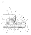
- FIGS. 3a and 3b the sequence of movement of the rocker 22 and the structural design of the rocker 22 and the guide carriage 10 is shown.
- the nose 29 is formed, which extends in the direction of the rocker 22 and acts on them.
- the nose 29 is inserted into a machined into the surface 25 of the rocker 22 notch 27.
- the outwardly projecting outer wall of the notch 27 is indicated by the reference numeral 28.
- the outer wall 28 is inclined in the direction of the nose 29 and forms in the starting position with this an undercut in order to achieve the largest possible contact between the outer wall 28 and the nose 29, so that the transmitted forces from the cover 21 via the rocker 22 and the outer wall 28 and the nose 29 are reliably supported, whereby the housing 5 is stabilized in the closed state of the lid 21.
- an inclined surface 26 is on the surface 25 of the rocker 22, which is aligned from the inside out and immediately laterally offset from the outside of the nose 29 is arranged.
- FIG. 3b can be seen that the nose 29 acts upon pivoting of the guide carriage 10 about the retaining bolt 14 on the inclined surface 26 and thus exerts a substantially vertical force on one side of the rocker 22, so that the rocker 22 through the nose 29 in the direction the milling disc 3 is pressed, that is pivoted about the axis of rotation 24 formed by the bearing pin 23.
- This causes on the opposite side of the bearing pin 23 of the rocker 22 to which the lid 21 is mounted, lifting the lid 21, so that between the bottom of the housing 5 and the lid 21, an air gap is formed by the milling disc 3 from the Housing 5 is pushed out.
- the stroke, the rocker 22 travels when driving over the nose 29 along the inclined surface 26, is dimensioned larger than the Verschwenkweg that the cutter disk 3 in the direction of the cover 21 during pivoting of the guide carriage 10 travels. This ensures that the milling disc 3 is not obstructed in its movement through the cover 21, but that the lid 21 releases a suitably large air gap, through which the milling disc 3 can be moved out of the housing 5.
- the nose 29 releases the rocker 22, so that it rests along the inclined surface 26, which rests against the nose 29, in the starting position by means of a between the cover plate 6 and the rocker 22
- Helical compression spring 31 is pushed back.
- the helical compression spring 31 is advantageously arranged between the notch 27 and the bearing pin 23.
- FIGS. 4a . 4b and FIG. 5 shows a further exemplary embodiment for mounting the rocker 22.
- the pivoting of the rocker 22 is achieved in that on the surface of the guide carriage 10, which faces the rocker 22, a pressure plane 34 is incorporated.
- a pressure plane 34 is incorporated on the surface of the guide carriage 10, which faces the rocker 22, a pressure plane 34 is incorporated.
- the pressure plane 34 while acting in the direction of the rocker 22 holding force is generated, which acts on the upwardly projecting outer wall 28.
- the outer wall 28 projects beyond the plane formed by the rocker 22.
- the transition region between the recess 33 and the pressure plane 34 is inclined, in order to achieve as latch-free as possible depressing the outer wall 28.
Landscapes
- Engineering & Computer Science (AREA)
- Mechanical Engineering (AREA)
- Milling, Drilling, And Turning Of Wood (AREA)
- Grinding-Machine Dressing And Accessory Apparatuses (AREA)
- Processing Of Stones Or Stones Resemblance Materials (AREA)
Description
- Die Erfindung bezieht sich auf ein Handarbeitsgerät, insbesondere zum Durchtrennen von Bauteilen, nach dem Oberbegriff des Patentanspruches 1.
- Aus der
DE 10 2005 021 212 A1 ist ein solches Handarbeitsgerät zu entnehmen, dessen Frässcheibe sowohl nach vorne aus dem Gehäuse des Handarbeitsgerätes als auch aus einer Austrittsöffnung, die seitlich und senkrecht zu der ersten Austrittsöffnung verläuft, herausgedrückt werden kann. Durch diese Bewegungsmöglichkeiten der Frässcheibe ist gewährleistet, dass die Frässcheibe aus einem der vier Eckbereiche des Gehäuses herausfahrbar ist, so dass in engen, schwer zugänglichen Nischen oder Ecken, insbesondere von Fenstern, die Frässcheibe in das Mauerwerk eindringen kann. - Diese Handarbeitsgeräte haben sich in der Praxis zwar bewährt, weisen jedoch den Nachteil auf, da bei jeder Vorwärtsbewegung der Frässcheibe der verschwenkbar gelagerte Deckel mitgeöffnet ist. Dadurch ist zum einen die Stabilität des Gehäuses reduziert, da diese Seite des Gehäuses nicht abgestützt ist, und zum anderen sind zusätzliche Kräfte aufzuwenden, um den Deckel zu bewegen.
- Es ist daher Aufgabe der Erfindung, ein Handarbeitsgerät der vorgenannten Gattung bereitzustellen, dessen Gehäuse derart stabil ausgestaltet ist, dass zwar zwei Stirnseiten des Gehäuses für den Durchtritt der Frässcheibe geöffnet werden können, dass jedoch eine der Stirnseiten solange verschlossen ist bis die Frässcheibe tatsächlich aus dieser herausgeschoben werden soll und dass gleichzeitig die Frässcheibe aus zwei benachbarten Stirnseiten des Gehäuses herausfahrbar ist, um einen möglichst groß bemessenen Arbeitsbereich für die Frässcheibe zu erreichen.
- Diese Aufgabe wird erfindungsgemäß durch die Merkmale des kennzeichnenden Teils von Patentanspruch 1 gelöst.
- Weitere vorteilhafte Weiterbildungen der Erfindung ergeben sich aus den Unteransprüchen.
- Dadurch, dass eine der beiden Austrittsöffnungen mittels eines Deckels verschlossen ist, der über eine Wippe sowohl an dem Gehäuse als auch an dem Führungsschlitten anliegt und mit diesen Bauteilen zusammenwirkt, ist erreicht, dass der Deckel die in diesen eingeleitete Kräfte aufnimmt und diese zuverlässig weiterleitet, zumindest dann, wenn der Deckel geschlossen ist. Durch den Deckel ist demnach die Stabilität des Gehäuses in dieser geschlossenen Stellung erhöht. Da der Deckel ausschließlich dann angehoben ist, wenn die Frässcheibe auch aus dieser Stirnseite herausgeschoben ist, benötigt der Benutzer zum einen während der üblichen Betriebsstellung keine zusätzlichen Kräfte, um die Wippe zu betätigen, sondern erst dann, wenn der Deckel zu öffnen ist, und zum anderen ist das Gehäuse bei geschlossenem Deckel durch diesen stabilisiert. Folglich ist der Deckel vorteilhafterweise als Abstützhilfe anzusehen, so dass das Gehäuse nunmehr entlang von drei Stirnseiten abgestützt ist.
- Es ist besonders vorteilhaft, wenn zwischen der Wippe und dem Führungsschlitten eine Hinterschneidung gebildet ist, denn durch diese zusätzliche Anlagefläche wird die Stabilisierung des Deckels in geschlossenem Zustand vergrößert.
- Darüber hinaus ist durch den Verschluss einer der beiden Austrittsöffnungen erreicht, dass der durch den Fräsvorgang anfallende Staub nicht aus einer weiteren Austrittsöffnung für die Frässcheibe herausgeschleudert ist und die Umgebung verschmutzt.
- In der Zeichnung sind zwei erfindungsgemäße Ausführungsbeispiele dargestellt, die nachfolgend näher erläutert sind. Im Einzelnen zeigt:
- Figur 1
- ein erstes Ausführungsbeispiel eines Handarbeitsgerätes, mit einem Antriebsmotor, einer trieblich mit diesem verbundenen Welle und mit einer an der Welle angebrachten Frässcheibe, die durch zwei senkrecht zueinander ausgerichteten Austrittsöffnungen herausfahrbar ist, im Schnitt,
- Figur 2a
- das Handarbeitsgerät gemäß
Fig. 1 in Draufsicht und in der Ausgangsstellung, - Figur 2b
- das Handarbeitsgerät gemäß
Fig. 2a in einem vollständig ausgefahrenen Zustand der Frässcheibe, - Figur 3a
- das Handarbeitsgerät gemäß
Fig. 2a entlang der Schnittlinie IIIa-IIIa, - Figur 3b
- das Handarbeitsgerät gemäß
Fig. 2b entlang der Schnittlinie IIIb-IIIb und - Figur 4a
- ein zweites Ausführungsbeispiel eines Handarbeitsgerätes, mit einem Antriebsmotor, einer trieblich mit diesem verbundenen Welle und mit einer an der Welle angebrachten Frässcheibe, die durch zwei senkrecht zueinander ausgerichteten Austrittsöffnungen herausfahrbar ist, im Schnitt und im Ausgangszustand und
- Figur 4b
- das Handarbeitsgemäß
Figur 4a in einem vollständig ausgefahrenen Zustand. - Aus den
Figuren 1 bis 4 ist jeweils ein Handarbeitsgerät 1 zu entnehmen, durch das insbesondere Fensterrahmen, die in einem Mauerwerk mittels Metallbügel gehalten sind, zu Sanierungszwecken herausgelöst werden sollen. Das Handarbeitsgerät 1 besteht dabei aus einem Antriebsmotor 2, der trieblich über eine Welle 4 mit einer Frässcheibe 3 verbunden ist. Die Frässcheibe 3 soll in das Mauerwerk eindringen und die Metallbügel durchschneiden, um den Fensterrahmen aus dem Mauerwerk herauslösen zu können. - Zur Kraftübertragung zwischen dem Handarbeitsgerät 1, der Frässcheibe 3 und den einzelnen Metallbügeln ist ein Gehäuse 5 vorgesehen, durch das die Frässcheibe 3 nahezu vollständig gekapselt ist.
- Um die Frässcheibe 3 nunmehr aus einer ersten Austrittsöffnung 12, die in eine Stirnseite des Gehäuses 5 eingearbeitet ist, herausfahren zu können, ist in einer dem Antriebsmotor 2 zugewandten Abdeckplatte 6 des Gehäuses 5 ein Langloch 7 eingearbeitet. Das Langloch 7 wird von der Welle 4 durchgriffen, so dass der Antriebsmotor 2 und die Frässcheibe 3 in Richtung auf die erste Austrittsöffnung 12 verschiebbar sind. Zur seitlichen Führung des Antriebsmotors 2 ist auf der Abdeckplatte 6 ein Führungsschlitten 10 montiert, der zunächst über einen Haltebolzen 14 verschwenkbar mit dem Gehäuse 5 verbunden ist. Zum anderen ist in die Abdeckplatte 6 eine bogenförmige Führungsnut 17 eingearbeitet.
- Das Langloch 7 weist insgesamt zwei Führungsabschnitte 8 und 9 auf. Der erste Führungsabschnitt 8 verläuft fluchtend zu der Längsachse 11; der zweite Führungsabschnitt 9 mündet nahezu senkrecht von dem ersten Führungsabschnitt 8 in Richtung einer zweiten Austrittsöffnung 13 ab. Somit verlaufen die jeweiligen Führungsabschnitte 8 bzw. 9 senkrecht zu der ersten bzw. zweiten Austrittsöffnung 12 oder 13.
- Durch diese konstruktive Ausgestaltung des Handarbeitsgerätes 1 ist gewährleistet, dass der Antriebsmotor 2, die Frässcheibe 3 und die Welle 4 in Richtung der ersten Austrittsöffnung 12, also entlang der Längsachse 11 verschoben werden können, und dass in dieser Arbeitsposition die Frässcheibe 3 aus der ersten Austrittsöffnung 12 hervorragt. Wenn es nunmehr erforderlich ist, dass die Frässcheibe 3 auch aus der zweiten Austrittsöffnung 13 herauszufahren ist, um beispielsweise in Eckbereichen eines Mauerwerkes schwer zugängliche Metallclipse in diesem zu lösen, wird zunächst der Führungsschlitten 10 um den Haltebolzen 14 verschwenkt. Diese Verschwenkbewegung wird durch die bogenförmige Führungsnut 17 in der Form unterstützt, dass durch diese die Bewegungsmöglichkeit des Führungsschlittens 10 in Richtung der zweiten Austrittsöffnung 13 nicht behindert ist. Die bogenförmige Führungsnut 17 stützt jedoch bei der axialen Verschiebung des Antriebsmotors 2 den Führungsschlitten 10 ab, so dass dieser in Richtung der Längsachse 11 durch den Haltebolzen 14 und den in die Führungsnut 17 eingreifenden Haltebolzen 18 an der Abdeckplatte 6 gehalten ist.
- In den Führungsschlitten 10 ist eine schlitzartige Öffnung 15 eingearbeitet, die ebenso von der Welle 4 durchgriffen ist. Folglich kann der Führungsschlitten 10 erst dann um den Mittelpunkt des Haltebolzens 14 verschwenkt werden, wenn die Welle 4 im Übergangsbereich zwischen dem ersten und dem zweiten Abschnitt 8 und 9 angeordnet ist.
- Insbesondere den
Figuren 2a ,2b ,3a und3b ist zu entnehmen, dass die zweite Austrittsöffnung 13 mittels eines Deckels 21, der verschwenkbar an dem Gehäuse 5, wie dies nachfolgend noch näher erläutert wird, abgestützt ist, verschlossen ist. Durch den Deckel 21 ist demnach eine Kraftübertragung im Bereich der zweiten Austrittsöffnung 13 erreicht, so dass Kräfte, die in diesem Bereich auftreten, über den Deckel 21 aufgenommen werden. Die Stabilität des Gehäuses 5 ist somit im Bereich der zweiten Austrittsöffnung 13 einem in diesem Bereich geschlossenen Gehäuse nachgebildet. - Wird anschließend der Führungsschlitten 10 in den zweiten Führungs-Abschnitt 9 eingeschoben, also um den Haltebolzen 14 verschwenkt, wirkt der Führungsschlitten 10 auf eine diesem zugewandte Wippe 22 ein und drückt diesen Bereich der Wippe 22 in das Innere der Abdeckplatte 6, da an dem Führungsschlitten 10 eine Nase 29 angebracht ist, die hakenförmig in Richtung der Wippe 22 absteht. Der Deckel 21 ist an der dem Führungsschlitten 10 gegenüberliegenden Seite der Wippe 22 fest angebracht, so dass beim Herunterdrücken der einen Seite der Wippe 22 die andere Seite der Wippe 22 angehoben ist, so dass der Deckel 21 die zweite Austrittsöffnung 13 freigibt.
- Die Wippe 22 ist dabei mittels eines Lagerbolzens 23 in der Abdeckplatte 6 verschwenkbar gelagert, so dass durch den Lagerbolzen 23 eine Drehachse 24 gebildet ist, die senkrecht zu der ersten Austrittsöffnung 12 verläuft. Die Wippe 22 ist seitlich versetzt zu der ersten Austrittsöffnung 12 und parallel zu dieser angeordnet.
- In den
Figuren 3a und3b ist der Bewegungsablauf der Wippe 22 sowie die konstruktive Ausgestaltung der Wippe 22 und des Führungsschlittens 10 gezeigt. An dem Führungsschlitten 10 ist dabei die nach innen geneigt verlaufende, also vor dem Handarbeitsgerät 1 abstehende Nase 29 angeformt, die in Richtung der Wippe 22 verläuft und auf diese einwirkt. In dem inFigur 3a gezeigten Ausgangszustand der Wippe 22 ist die Nase 29 in eine in die Oberfläche 25 der Wippe 22 eingearbeitete Kerbe 27 eingesetzt. Die nach außen ragende Außenwand der Kerbe 27 ist mit der Bezugsziffer 28 gekennzeichnet. Die Außenwand 28 ist in Richtung der Nase 29 geneigt und bildet in der Ausgangsposition mit dieser eine Hinterschneidung, um eine möglichst großflächige Anlage zwischen der Außenwand 28 und der Nase 29 zu erreichen, so dass die von dem Deckel 21 übertragenen Kräfte über die Wippe 22 und der Außenwand 28 bzw. der Nase 29 zuverlässig abgestützt sind, wodurch das Gehäuse 5 in geschlossenem Zustand des Deckels 21 stabilisiert ist. - Zwischen der Kerbe 27 und dem Lagerbolzen 23 ist auf der Oberfläche 25 der Wippe 22 eine schräge Fläche 26 angearbeitet, die von innen nach außen ausgerichtet ist und unmittelbar seitlich versetzt zu der Außenseite der Nase 29 angeordnet ist.
- Aus
Figur 3b kann entnommen werden, dass die Nase 29 beim Verschwenken des Führungsschlittens 10 um den Haltebolzen 14 auf die schräge Fläche 26 einwirkt und somit eine im Wesentlichen vertikal verlaufende Kraft auf eine Seite der Wippe 22 ausübt, so dass die Wippe 22 durch die Nase 29 in Richtung der Frässcheibe 3 gedrückt ist, also um die von dem Lagerbolzen 23 gebildete Drehachse 24 verschwenkt ist. Dies bewirkt auf der dem Lagerbolzen 23 gegenüberliegenden Seite der Wippe 22, an der der Deckel 21 angebracht ist, ein Anheben des Deckels 21, so dass zwischen der Unterseite des Gehäuses 5 und dem Deckel 21 ein Luftspalt entsteht, durch den die Frässcheibe 3 aus dem Gehäuse 5 herausgedrückt ist. - Der Hubweg, den die Wippe 22 beim Überfahren der Nase 29 entlang der schrägen Fläche 26 zurücklegt, ist dabei größer bemessen als der Verschwenkweg, den die Frässcheibe 3 in Richtung auf den Deckel 21 beim Verschwenken des Führungsschlittens 10 zurücklegt. Dadurch ist sichergestellt, dass die Frässcheibe 3 nicht in ihrer Bewegung durch den Deckel 21 behindert ist, sondern dass der Deckel 21 einen geeignet großen Luftspalt freigibt, durch den die Frässcheibe 3 aus dem Gehäuse 5 herausfahrbar ist.
- Wird der Führungsschlitten 10 aus dem zweiten Abschnitt 9 zurückbewegt, gibt die Nase 29 die Wippe 22 frei, so dass diese entlang der schrägen Fläche 26, die an der Nase 29 anliegt, in die Ausgangsposition mittels einer zwischen der Abdeckplatte 6 und der Wippe 22 angeordneten Schraubendruckfeder 31 zurückgedrückt ist. Die Schraubendruckfeder 31 ist vorteilhafterweise zwischen der Kerbe 27 und dem Lagerbolzen 23 angeordnet.
- In den
Figuren 4a ,4b und 5 ist ein weiteres Ausführungsbeispiel zur Lagerung der Wippe 22 abgebildet. Das Verschwenken der Wippe 22 wird dadurch erreicht, dass auf der Oberfläche des Führungsschlittens 10, die der Wippe 22 zugewandt ist, eine Druckebene 34 eingearbeitet ist. Durch die Druckebene 34 wird dabei eine in Richtung der Wippe 22 wirkende Haltekraft erzeugt, die auf die nach oben abstehende Außenwand 28 einwirkt. Die Außenwand 28 steht über die von der Wippe 22 gebildeten Ebene über. Im Ausgangszustand taucht die Außenwand 28 in eine Aussparung 33 ein, so dass diese die Verschwenkbewegung des Führungsschlittens 10 nicht behindert. Der Übergangsbereich zwischen der Aussparung 33 und der Druckebene 34 verläuft geneigt, um ein möglichst verrastfreies Herunterdrücken der Außenwand 28 zu erreichen. - Sollte die Wippe 22 in die Ausgangslage nicht selbstständig zurückschnappen, wird diese durch die Nase 29 hochgezogen, der zwischen der Nase 29 und der Außenwand eine geneigte Auflagefläche 32 vorgesehen ist, so dass die Nase 29 beim Zurückfahren die Außenwand 28 und folglich die Wippe 22 nach oben zieht.
Claims (9)
- Handarbeitsgerät (1), insbesondere zum Durchtrennen von Bauteilen, bestehend aus einem Antriebsmotor (2), aus einer Frässcheibe (3), die mit dem Antriebsmotor (2) über eine Welle (4) trieblich verbunden ist, aus einem die Frässcheibe (3) umschließenden Gehäuse (5), in dem in der dem Antriebsmotor (2) zugewanden Abdeckplatte (6) ein aus zwei schlitzartigen FührungsAbschnitten (8, 9) zusammengesetztes Langloch (7) eingearbeitet ist, das von der Welle (4) durchgriffen ist und dessen beide Abschnitte (8, 9) jeweils etwa senkrecht in Richtung zu einer in dem Gehäuse (5) vorgesehenen Austrittsöffnung (12, 13) verlaufen, aus einem Führungsschlitten (10), der auf der Abdeckplatte (6) des Gehäuses (5) verschwenkbar um einen Haltebolzen (14) arretiert ist und der eine schlitzartige Öffnung (15) aufweist, die fluchtend zu dem ersten Abschnitt (8) des Langlochs (7) ausgerichtet und durch die die Welle (4) hindurch geführt ist, wobei der Antriebsmotor (2) an dem Führungsschlitten (10) verschieblich in Richtung der dem ersten Abschnitt (8) zugeordneten Austrittsöffnung (12) gehalten ist,
dadurch gekennzeichnet,
dass die dem zweiten Abschnitt (9) des Langlochs (7) zugewandte Austrittsöffnung (13) mittels eines Deckels (21) verschlossen ist, dass der Deckel (21) mindestens an einer in der Abdeckplatte (6) verschwenkbar gelagerten Wippe (22) gekoppelt ist und dass durch den Führungsschlitten (10) eine dem Deckel (21) abgewandten Seite der Wippe (22) überfahrbar und diese in das Innere der Abdeckplatte (6) eindrückbar ist. - Handarbeitsgerät nach Anspruch 1,
dadurch gekennzeichnet,
dass die Wippe (22) parallel und seitlich versetzt zu der dem ersten Abschnitt (8) des Langlochs (7) zugeordneten Austrittsöffnung (12) verläuft. - Handarbeitsgerät nach Anspruch 2,
dadurch gekennzeichnet,
dass etwa fluchtend oder seitlich versetzt zu der Längsachse der Wippe (22) auf der gegenüberliegenden Seite des Führungsabschnittes (9) eine bogenförmige Führungsnut (17) in die Abdeckplatte (6) des Gehäuses (5) eingearbeitet ist, in die ein an dem Führungsschlitten (10) angebrachter Haltebolzen (18) eingreift, dass die Führungsnut (17) in den ersten Abschnitt (8) des Langloches (7) mündet und dass der Beginn der Führungsnut (17) gemeinsam mit dem Mittelpunkt des Haltebolzens (18) eine Achse bildet, die parallel oder geneigt zu der Längsachse (11) des Führungsschlittens (10) verläuft. - Handarbeitsgerät nach einem der vorgenannten Ansprüche,
dadurch gekennzeichnet,
dass auf der der Wippe (22) zugewandten Seite des Führungsschlittens (10) eine, vorzugsweise nach innen geneigt verlaufende, Nase (29) angeformt ist, die im geschlossenen Zustand des Deckels (21) in eine in die Wippe (22) eingearbeitete Kerbe (27) eingreift und die mit der Außenwand (28) der Kerbe (27) eine Hinterschneidung zur an dem Führungsschlitten (10) geneigten Anlagefläche (32) bildet. - Handarbeitsgerät nach einem der vorgenannten Ansprüche 1 bis 3,
dadurch gekennzeichnet,
dass die Oberfläche (25) der Wippe (22), die dem Führungsschlitten (10) zugewandt ist, bereichsweise als von innen nach außen geneigte und in Richtung des Deckels (21) verlaufende schräge Fläche (26) ausgestaltet ist und dass an dem Führungsschlitten (10) eine der schrägen Fläche (26) zugewandte Nase (29) angeformt ist, durch die die Wippe (22) in das Innere des Gehäuses (5) eindrückbar ist. - Handarbeitsgerät nach einem der vorgenannten Ansprüche,
dadurch gekennzeichnet,
dass an der Wippe (22) eine Schraubendruckfeder (31) zwischen dem Führungsschlitten (10) und der Aufhängung (23) der Wippe (22) vorgesehen ist, durch die diese in die Ausgangsposition bewegbar ist. - Handarbeitsgerät nach einem der vorgenannten Ansprüche,
dadurch gekennzeichnet,
dass die Querschnittsform des Deckels (21) bogen- oder kreisförmig oder schräg abgelenkt ausgebildet ist. - Handarbeitsgerät nach einem der vorgenannten Ansprüche,
dadurch gekennzeichnet,
dass das von dem Hebelarm der Wippe (22) und der Steigung der schrägen Fläche (26) gebildete Übersetzungsverhältnis derart bemessen ist, dass in jeder Betriebsstellung der Frässcheibe (3) zwischen dieser und dem_Deckel (21) ein Luftspalt vorhanden ist. - Handarbeitsgerät nach einem der vorgenannten Ansprüche,
dadurch gekennzeichnet,
dass an dem Deckel (21) ein weiterer Hebelarm (30) angebracht ist, der parallel zu der Wippe (22) verläuft und der in der Auflageplatte (6) des Gehäuses (5) verschwenkbar gelagert ist.
Applications Claiming Priority (1)
| Application Number | Priority Date | Filing Date | Title |
|---|---|---|---|
| DE102010009778A DE102010009778A1 (de) | 2010-03-01 | 2010-03-01 | Handarbeitsgerät |
Publications (2)
| Publication Number | Publication Date |
|---|---|
| EP2363242A1 EP2363242A1 (de) | 2011-09-07 |
| EP2363242B1 true EP2363242B1 (de) | 2013-05-01 |
Family
ID=44117228
Family Applications (1)
| Application Number | Title | Priority Date | Filing Date |
|---|---|---|---|
| EP20110154439 Active EP2363242B1 (de) | 2010-03-01 | 2011-02-15 | Handarbeitsgerät |
Country Status (3)
| Country | Link |
|---|---|
| EP (1) | EP2363242B1 (de) |
| DE (1) | DE102010009778A1 (de) |
| ES (1) | ES2423664T3 (de) |
Cited By (1)
| Publication number | Priority date | Publication date | Assignee | Title |
|---|---|---|---|---|
| EP3246128A1 (de) | 2016-05-17 | 2017-11-22 | Eberhard Berhalter | Handwerkzeugmaschinenvorrichtung zu einer beweglichen lagerung einer welle in einer führungsbahn |
Family Cites Families (4)
| Publication number | Priority date | Publication date | Assignee | Title |
|---|---|---|---|---|
| DE3722818A1 (de) * | 1987-07-10 | 1989-01-19 | Robert Wolff | Vorrichtung zum fraesen von nuten oder schattenfugen |
| DE202005002939U1 (de) * | 2005-02-18 | 2005-06-23 | Tischer, Karsten | Antriebseinheit für offroad RC-Car 1:6 |
| DE102005019388A1 (de) * | 2005-04-28 | 2006-11-02 | Robert Bosch Gmbh | Strömungsmittelgetriebene Handwerkzeugmaschine |
| DE102005021212B4 (de) | 2005-05-07 | 2018-05-09 | Eberhard Berhalter | Handarbeitsgerät |
-
2010
- 2010-03-01 DE DE102010009778A patent/DE102010009778A1/de not_active Withdrawn
-
2011
- 2011-02-15 EP EP20110154439 patent/EP2363242B1/de active Active
- 2011-02-15 ES ES11154439T patent/ES2423664T3/es active Active
Cited By (2)
| Publication number | Priority date | Publication date | Assignee | Title |
|---|---|---|---|---|
| EP3246128A1 (de) | 2016-05-17 | 2017-11-22 | Eberhard Berhalter | Handwerkzeugmaschinenvorrichtung zu einer beweglichen lagerung einer welle in einer führungsbahn |
| DE102016109049A1 (de) | 2016-05-17 | 2017-11-23 | Eberhard Berhalter | Handwerkzeugmaschinenvorrichtung zu einer beweglichen Lagerung einer Welle in einer Führungsbahn |
Also Published As
| Publication number | Publication date |
|---|---|
| DE102010009778A1 (de) | 2011-09-01 |
| EP2363242A1 (de) | 2011-09-07 |
| ES2423664T3 (es) | 2013-09-23 |
Similar Documents
| Publication | Publication Date | Title |
|---|---|---|
| EP0238848B1 (de) | Befestigungsvorrichtung mit einem Klemmverschluss zum lösbaren Angreifen an Hinterschneidungen aufweisenden Profilen | |
| DE102013200061B4 (de) | Schneidwerkzeug mit Wechsel-Klinge sowie Verfahren zum Austausch einer Wechsel-Klinge | |
| EP1964635B1 (de) | Hubsäge, insbesondere Stichsäge | |
| EP3843959B1 (de) | Messer mit einem messergriff und einer klinge | |
| DE69817675T2 (de) | Sägemaschine mit hin- und hergehendem Sägeblatt und Sägeblattspannvorrichtung mit mehrfacher Sägeblattspannposition | |
| EP2408600A1 (de) | Schnellspanneinrichtung für eine kettensäge und ketteneinheit für dieselbe | |
| DE3107199A1 (de) | Vorrichtung zum schneiden und/oder stanzen | |
| DE3208989A1 (de) | Anschlagvorrichtung, insbesondere fuer stanzmaschinen | |
| DE102015107720B3 (de) | Schienengeführtes Schneidwerkzeug | |
| DE29914341U1 (de) | Drehknopf-Schalteinrichtung | |
| EP2199001B1 (de) | Stichsäge mit einer Sägeblattaufnahme | |
| DE3006968A1 (de) | Geraet zum schneiden von flachen boden- oder wandbelaegen | |
| EP2363242B1 (de) | Handarbeitsgerät | |
| EP1622731B1 (de) | Werkzeugaufnahmevorrichtung | |
| AT502038A4 (de) | Sicherheitseinrichtung für eine abkantpresse und ein lamellenwerkzeug | |
| EP1693170B1 (de) | Schutz- und Führungseinrichtung für ein Trenn- oder Schleifgerät sowie Trenn- oder Schleifgerät mit einer solchen Schutz- und Führungseinrichtung | |
| DE112014006266B4 (de) | Gartenscheren mit Schnitt-Umschaltmodus | |
| DE102013221566A1 (de) | Zweiteilige Schutzhaube für Trennschleifer | |
| DE202021101852U1 (de) | Keiltrieb mit einstellbarer Arbeits- und Montagestellung | |
| DE8906511U1 (de) | Stichsäge | |
| EP0855239A1 (de) | Schnellspannvorrichtung an einer Werkstück-Bearbeitungsmaschine | |
| DE202011050892U1 (de) | Kapp- und/oder Gehrungssäge | |
| DE102005021212B4 (de) | Handarbeitsgerät | |
| EP2641684A1 (de) | Handarbeitsgerät | |
| EP0711638A1 (de) | Werkstück-Vorschubwagen einer Werkzeugmaschine, insbesondere einer Kreissäge |
Legal Events
| Date | Code | Title | Description |
|---|---|---|---|
| PUAI | Public reference made under article 153(3) epc to a published international application that has entered the european phase |
Free format text: ORIGINAL CODE: 0009012 |
|
| AK | Designated contracting states |
Kind code of ref document: A1 Designated state(s): AL AT BE BG CH CY CZ DE DK EE ES FI FR GB GR HR HU IE IS IT LI LT LU LV MC MK MT NL NO PL PT RO RS SE SI SK SM TR |
|
| AX | Request for extension of the european patent |
Extension state: BA ME |
|
| 17P | Request for examination filed |
Effective date: 20120208 |
|
| 17Q | First examination report despatched |
Effective date: 20120618 |
|
| GRAP | Despatch of communication of intention to grant a patent |
Free format text: ORIGINAL CODE: EPIDOSNIGR1 |
|
| RIC1 | Information provided on ipc code assigned before grant |
Ipc: B24B 55/10 20060101AFI20121024BHEP Ipc: B24B 23/02 20060101ALI20121024BHEP Ipc: B24B 27/08 20060101ALI20121024BHEP |
|
| GRAS | Grant fee paid |
Free format text: ORIGINAL CODE: EPIDOSNIGR3 |
|
| GRAA | (expected) grant |
Free format text: ORIGINAL CODE: 0009210 |
|
| AK | Designated contracting states |
Kind code of ref document: B1 Designated state(s): AL AT BE BG CH CY CZ DE DK EE ES FI FR GB GR HR HU IE IS IT LI LT LU LV MC MK MT NL NO PL PT RO RS SE SI SK SM TR |
|
| REG | Reference to a national code |
Ref country code: GB Ref legal event code: FG4D Free format text: NOT ENGLISH |
|
| REG | Reference to a national code |
Ref country code: CH Ref legal event code: EP Ref country code: AT Ref legal event code: REF Ref document number: 609593 Country of ref document: AT Kind code of ref document: T Effective date: 20130515 |
|
| REG | Reference to a national code |
Ref country code: IE Ref legal event code: FG4D Free format text: LANGUAGE OF EP DOCUMENT: GERMAN |
|
| REG | Reference to a national code |
Ref country code: DE Ref legal event code: R082 Ref document number: 502011000681 Country of ref document: DE Representative=s name: WSL PATENTANWAELTE PARTNERSCHAFTSGESELLSCHAFT, DE Ref country code: DE Ref legal event code: R082 Ref document number: 502011000681 Country of ref document: DE Representative=s name: ENGELHARDT & ENGELHARDT PATENTANWAELTE, DE Ref country code: DE Ref legal event code: R082 Ref document number: 502011000681 Country of ref document: DE Representative=s name: PATENT- UND RECHTSANWALTSKANZLEI DAUB, DE |
|
| REG | Reference to a national code |
Ref country code: DE Ref legal event code: R082 Ref document number: 502011000681 Country of ref document: DE Representative=s name: PATENT- UND RECHTSANWALTSKANZLEI DAUB, DE Ref country code: DE Ref legal event code: R082 Ref document number: 502011000681 Country of ref document: DE Ref country code: DE Ref legal event code: R082 Ref document number: 502011000681 Country of ref document: DE Representative=s name: ENGELHARDT & ENGELHARDT PATENTANWAELTE, DE |
|
| REG | Reference to a national code |
Ref country code: DE Ref legal event code: R096 Ref document number: 502011000681 Country of ref document: DE Effective date: 20130704 |
|
| REG | Reference to a national code |
Ref country code: ES Ref legal event code: FG2A Ref document number: 2423664 Country of ref document: ES Kind code of ref document: T3 Effective date: 20130923 |
|
| REG | Reference to a national code |
Ref country code: NL Ref legal event code: VDEP Effective date: 20130501 |
|
| REG | Reference to a national code |
Ref country code: LT Ref legal event code: MG4D |
|
| PG25 | Lapsed in a contracting state [announced via postgrant information from national office to epo] |
Ref country code: FI Free format text: LAPSE BECAUSE OF FAILURE TO SUBMIT A TRANSLATION OF THE DESCRIPTION OR TO PAY THE FEE WITHIN THE PRESCRIBED TIME-LIMIT Effective date: 20130501 Ref country code: PT Free format text: LAPSE BECAUSE OF FAILURE TO SUBMIT A TRANSLATION OF THE DESCRIPTION OR TO PAY THE FEE WITHIN THE PRESCRIBED TIME-LIMIT Effective date: 20130902 Ref country code: SI Free format text: LAPSE BECAUSE OF FAILURE TO SUBMIT A TRANSLATION OF THE DESCRIPTION OR TO PAY THE FEE WITHIN THE PRESCRIBED TIME-LIMIT Effective date: 20130501 Ref country code: LT Free format text: LAPSE BECAUSE OF FAILURE TO SUBMIT A TRANSLATION OF THE DESCRIPTION OR TO PAY THE FEE WITHIN THE PRESCRIBED TIME-LIMIT Effective date: 20130501 Ref country code: SE Free format text: LAPSE BECAUSE OF FAILURE TO SUBMIT A TRANSLATION OF THE DESCRIPTION OR TO PAY THE FEE WITHIN THE PRESCRIBED TIME-LIMIT Effective date: 20130501 Ref country code: NO Free format text: LAPSE BECAUSE OF FAILURE TO SUBMIT A TRANSLATION OF THE DESCRIPTION OR TO PAY THE FEE WITHIN THE PRESCRIBED TIME-LIMIT Effective date: 20130801 Ref country code: IS Free format text: LAPSE BECAUSE OF FAILURE TO SUBMIT A TRANSLATION OF THE DESCRIPTION OR TO PAY THE FEE WITHIN THE PRESCRIBED TIME-LIMIT Effective date: 20130901 Ref country code: GR Free format text: LAPSE BECAUSE OF FAILURE TO SUBMIT A TRANSLATION OF THE DESCRIPTION OR TO PAY THE FEE WITHIN THE PRESCRIBED TIME-LIMIT Effective date: 20130802 |
|
| PG25 | Lapsed in a contracting state [announced via postgrant information from national office to epo] |
Ref country code: BG Free format text: LAPSE BECAUSE OF FAILURE TO SUBMIT A TRANSLATION OF THE DESCRIPTION OR TO PAY THE FEE WITHIN THE PRESCRIBED TIME-LIMIT Effective date: 20130801 Ref country code: HR Free format text: LAPSE BECAUSE OF FAILURE TO SUBMIT A TRANSLATION OF THE DESCRIPTION OR TO PAY THE FEE WITHIN THE PRESCRIBED TIME-LIMIT Effective date: 20130501 Ref country code: PL Free format text: LAPSE BECAUSE OF FAILURE TO SUBMIT A TRANSLATION OF THE DESCRIPTION OR TO PAY THE FEE WITHIN THE PRESCRIBED TIME-LIMIT Effective date: 20130501 Ref country code: CY Free format text: LAPSE BECAUSE OF FAILURE TO SUBMIT A TRANSLATION OF THE DESCRIPTION OR TO PAY THE FEE WITHIN THE PRESCRIBED TIME-LIMIT Effective date: 20130501 Ref country code: RS Free format text: LAPSE BECAUSE OF FAILURE TO SUBMIT A TRANSLATION OF THE DESCRIPTION OR TO PAY THE FEE WITHIN THE PRESCRIBED TIME-LIMIT Effective date: 20130501 |
|
| PG25 | Lapsed in a contracting state [announced via postgrant information from national office to epo] |
Ref country code: LV Free format text: LAPSE BECAUSE OF FAILURE TO SUBMIT A TRANSLATION OF THE DESCRIPTION OR TO PAY THE FEE WITHIN THE PRESCRIBED TIME-LIMIT Effective date: 20130501 |
|
| PG25 | Lapsed in a contracting state [announced via postgrant information from national office to epo] |
Ref country code: SK Free format text: LAPSE BECAUSE OF FAILURE TO SUBMIT A TRANSLATION OF THE DESCRIPTION OR TO PAY THE FEE WITHIN THE PRESCRIBED TIME-LIMIT Effective date: 20130501 Ref country code: EE Free format text: LAPSE BECAUSE OF FAILURE TO SUBMIT A TRANSLATION OF THE DESCRIPTION OR TO PAY THE FEE WITHIN THE PRESCRIBED TIME-LIMIT Effective date: 20130501 Ref country code: DK Free format text: LAPSE BECAUSE OF FAILURE TO SUBMIT A TRANSLATION OF THE DESCRIPTION OR TO PAY THE FEE WITHIN THE PRESCRIBED TIME-LIMIT Effective date: 20130501 Ref country code: CZ Free format text: LAPSE BECAUSE OF FAILURE TO SUBMIT A TRANSLATION OF THE DESCRIPTION OR TO PAY THE FEE WITHIN THE PRESCRIBED TIME-LIMIT Effective date: 20130501 |
|
| PG25 | Lapsed in a contracting state [announced via postgrant information from national office to epo] |
Ref country code: NL Free format text: LAPSE BECAUSE OF FAILURE TO SUBMIT A TRANSLATION OF THE DESCRIPTION OR TO PAY THE FEE WITHIN THE PRESCRIBED TIME-LIMIT Effective date: 20130501 Ref country code: RO Free format text: LAPSE BECAUSE OF FAILURE TO SUBMIT A TRANSLATION OF THE DESCRIPTION OR TO PAY THE FEE WITHIN THE PRESCRIBED TIME-LIMIT Effective date: 20130501 |
|
| PLBE | No opposition filed within time limit |
Free format text: ORIGINAL CODE: 0009261 |
|
| STAA | Information on the status of an ep patent application or granted ep patent |
Free format text: STATUS: NO OPPOSITION FILED WITHIN TIME LIMIT |
|
| 26N | No opposition filed |
Effective date: 20140204 |
|
| REG | Reference to a national code |
Ref country code: DE Ref legal event code: R097 Ref document number: 502011000681 Country of ref document: DE Effective date: 20140204 |
|
| BERE | Be: lapsed |
Owner name: BERHALTER, EBERHARD Effective date: 20140228 |
|
| PG25 | Lapsed in a contracting state [announced via postgrant information from national office to epo] |
Ref country code: MC Free format text: LAPSE BECAUSE OF FAILURE TO SUBMIT A TRANSLATION OF THE DESCRIPTION OR TO PAY THE FEE WITHIN THE PRESCRIBED TIME-LIMIT Effective date: 20130501 Ref country code: LU Free format text: LAPSE BECAUSE OF FAILURE TO SUBMIT A TRANSLATION OF THE DESCRIPTION OR TO PAY THE FEE WITHIN THE PRESCRIBED TIME-LIMIT Effective date: 20140215 |
|
| REG | Reference to a national code |
Ref country code: CH Ref legal event code: PL |
|
| PG25 | Lapsed in a contracting state [announced via postgrant information from national office to epo] |
Ref country code: LI Free format text: LAPSE BECAUSE OF NON-PAYMENT OF DUE FEES Effective date: 20140228 Ref country code: CH Free format text: LAPSE BECAUSE OF NON-PAYMENT OF DUE FEES Effective date: 20140228 |
|
| REG | Reference to a national code |
Ref country code: IE Ref legal event code: MM4A |
|
| PG25 | Lapsed in a contracting state [announced via postgrant information from national office to epo] |
Ref country code: IE Free format text: LAPSE BECAUSE OF NON-PAYMENT OF DUE FEES Effective date: 20140215 Ref country code: BE Free format text: LAPSE BECAUSE OF NON-PAYMENT OF DUE FEES Effective date: 20140228 |
|
| PGFP | Annual fee paid to national office [announced via postgrant information from national office to epo] |
Ref country code: ES Payment date: 20150223 Year of fee payment: 5 |
|
| REG | Reference to a national code |
Ref country code: FR Ref legal event code: PLFP Year of fee payment: 6 |
|
| PG25 | Lapsed in a contracting state [announced via postgrant information from national office to epo] |
Ref country code: MT Free format text: LAPSE BECAUSE OF FAILURE TO SUBMIT A TRANSLATION OF THE DESCRIPTION OR TO PAY THE FEE WITHIN THE PRESCRIBED TIME-LIMIT Effective date: 20130501 |
|
| REG | Reference to a national code |
Ref country code: DE Ref legal event code: R082 Ref document number: 502011000681 Country of ref document: DE Representative=s name: PATENT- UND RECHTSANWALTSKANZLEI DAUB, DE Ref country code: DE Ref legal event code: R082 Ref document number: 502011000681 Country of ref document: DE |
|
| REG | Reference to a national code |
Ref country code: DE Ref legal event code: R082 Ref document number: 502011000681 Country of ref document: DE Representative=s name: PATENT- UND RECHTSANWALTSKANZLEI DAUB, DE |
|
| PG25 | Lapsed in a contracting state [announced via postgrant information from national office to epo] |
Ref country code: SM Free format text: LAPSE BECAUSE OF FAILURE TO SUBMIT A TRANSLATION OF THE DESCRIPTION OR TO PAY THE FEE WITHIN THE PRESCRIBED TIME-LIMIT Effective date: 20130501 |
|
| PG25 | Lapsed in a contracting state [announced via postgrant information from national office to epo] |
Ref country code: HU Free format text: LAPSE BECAUSE OF FAILURE TO SUBMIT A TRANSLATION OF THE DESCRIPTION OR TO PAY THE FEE WITHIN THE PRESCRIBED TIME-LIMIT; INVALID AB INITIO Effective date: 20110215 Ref country code: TR Free format text: LAPSE BECAUSE OF FAILURE TO SUBMIT A TRANSLATION OF THE DESCRIPTION OR TO PAY THE FEE WITHIN THE PRESCRIBED TIME-LIMIT Effective date: 20130501 |
|
| REG | Reference to a national code |
Ref country code: FR Ref legal event code: PLFP Year of fee payment: 7 |
|
| REG | Reference to a national code |
Ref country code: AT Ref legal event code: MM01 Ref document number: 609593 Country of ref document: AT Kind code of ref document: T Effective date: 20160215 |
|
| PG25 | Lapsed in a contracting state [announced via postgrant information from national office to epo] |
Ref country code: ES Free format text: LAPSE BECAUSE OF NON-PAYMENT OF DUE FEES Effective date: 20160216 Ref country code: AT Free format text: LAPSE BECAUSE OF NON-PAYMENT OF DUE FEES Effective date: 20160215 |
|
| REG | Reference to a national code |
Ref country code: FR Ref legal event code: PLFP Year of fee payment: 8 |
|
| PG25 | Lapsed in a contracting state [announced via postgrant information from national office to epo] |
Ref country code: MK Free format text: LAPSE BECAUSE OF FAILURE TO SUBMIT A TRANSLATION OF THE DESCRIPTION OR TO PAY THE FEE WITHIN THE PRESCRIBED TIME-LIMIT Effective date: 20130501 |
|
| PG25 | Lapsed in a contracting state [announced via postgrant information from national office to epo] |
Ref country code: AL Free format text: LAPSE BECAUSE OF FAILURE TO SUBMIT A TRANSLATION OF THE DESCRIPTION OR TO PAY THE FEE WITHIN THE PRESCRIBED TIME-LIMIT Effective date: 20130501 |
|
| PGFP | Annual fee paid to national office [announced via postgrant information from national office to epo] |
Ref country code: IT Payment date: 20190226 Year of fee payment: 9 Ref country code: GB Payment date: 20190221 Year of fee payment: 9 |
|
| PGFP | Annual fee paid to national office [announced via postgrant information from national office to epo] |
Ref country code: FR Payment date: 20190221 Year of fee payment: 9 |
|
| GBPC | Gb: european patent ceased through non-payment of renewal fee |
Effective date: 20200215 |
|
| PG25 | Lapsed in a contracting state [announced via postgrant information from national office to epo] |
Ref country code: FR Free format text: LAPSE BECAUSE OF NON-PAYMENT OF DUE FEES Effective date: 20200229 Ref country code: GB Free format text: LAPSE BECAUSE OF NON-PAYMENT OF DUE FEES Effective date: 20200215 |
|
| PG25 | Lapsed in a contracting state [announced via postgrant information from national office to epo] |
Ref country code: IT Free format text: LAPSE BECAUSE OF NON-PAYMENT OF DUE FEES Effective date: 20200215 |
|
| P01 | Opt-out of the competence of the unified patent court (upc) registered |
Effective date: 20230522 |
|
| PGFP | Annual fee paid to national office [announced via postgrant information from national office to epo] |
Ref country code: DE Payment date: 20260228 Year of fee payment: 16 |