EP2641684A1 - Handarbeitsgerät - Google Patents
Handarbeitsgerät Download PDFInfo
- Publication number
- EP2641684A1 EP2641684A1 EP13150540.6A EP13150540A EP2641684A1 EP 2641684 A1 EP2641684 A1 EP 2641684A1 EP 13150540 A EP13150540 A EP 13150540A EP 2641684 A1 EP2641684 A1 EP 2641684A1
- Authority
- EP
- European Patent Office
- Prior art keywords
- housing
- spacer plate
- hand tool
- receiving
- spacer
- Prior art date
- Legal status (The legal status is an assumption and is not a legal conclusion. Google has not performed a legal analysis and makes no representation as to the accuracy of the status listed.)
- Granted
Links
Images

Classifications
-
- B—PERFORMING OPERATIONS; TRANSPORTING
- B28—WORKING CEMENT, CLAY, OR STONE
- B28D—WORKING STONE OR STONE-LIKE MATERIALS
- B28D1/00—Working stone or stone-like materials, e.g. brick, concrete or glass, not provided for elsewhere; Machines, devices, tools therefor
- B28D1/02—Working stone or stone-like materials, e.g. brick, concrete or glass, not provided for elsewhere; Machines, devices, tools therefor by sawing
- B28D1/04—Working stone or stone-like materials, e.g. brick, concrete or glass, not provided for elsewhere; Machines, devices, tools therefor by sawing with circular or cylindrical saw-blades or saw-discs
- B28D1/044—Working stone or stone-like materials, e.g. brick, concrete or glass, not provided for elsewhere; Machines, devices, tools therefor by sawing with circular or cylindrical saw-blades or saw-discs the saw blade being movable on slide ways
-
- B—PERFORMING OPERATIONS; TRANSPORTING
- B23—MACHINE TOOLS; METAL-WORKING NOT OTHERWISE PROVIDED FOR
- B23D—PLANING; SLOTTING; SHEARING; BROACHING; SAWING; FILING; SCRAPING; LIKE OPERATIONS FOR WORKING METAL BY REMOVING MATERIAL, NOT OTHERWISE PROVIDED FOR
- B23D45/00—Sawing machines or sawing devices with circular saw blades or with friction saw discs
- B23D45/003—Sawing machines or sawing devices with circular saw blades or with friction saw discs for particular purposes
-
- B—PERFORMING OPERATIONS; TRANSPORTING
- B28—WORKING CEMENT, CLAY, OR STONE
- B28D—WORKING STONE OR STONE-LIKE MATERIALS
- B28D1/00—Working stone or stone-like materials, e.g. brick, concrete or glass, not provided for elsewhere; Machines, devices, tools therefor
- B28D1/18—Working stone or stone-like materials, e.g. brick, concrete or glass, not provided for elsewhere; Machines, devices, tools therefor by milling, e.g. channelling by means of milling tools
- B28D1/183—Hand tools, e.g. portable, motor driven
Definitions
- the invention relates to a hand tool, which can be used in particular for cutting a metal clip in a masonry, according to the preamble of the protection claim. 1
- such a hand tool which can be used for cutting out window frames used in masonry for renovation purposes.
- the window frames are connected with the help of a variety of metal clips with the masonry.
- the metal clips are plastered, so that the sawing or milling disc of the manual tool has to cut through both the masonry and the plaster and the respective metal clips. Once all metal clips are cut, the window frame can be removed.
- the user of the hand tool therefore has to carry a plurality of differently sized washers, plates or strips which are to be placed at the respective processing point on the window frame in order to guide the hand tool in the correct distance.
- the distance between the window frame and the kerf is variable compensated, so that the hand tool is advantageously positioned exactly on the front side of the masonry and rests kept guided.
- the spacer plates can be quickly and easily attached to the housing or stackable together.
- the user of the crafting device can recognize by means of different colors of spacer plates, which wall thickness has the respective spacer plate in order to make an optimal balance can.
- the spacer plate are firmly applied to the underside of the housing, which is designed wholly or partially plan to provide the largest possible bearing surface, the spacer plates do not move relative to the housing and not with each other, so that the leadership of the hand tool along the Masonry is accomplished.
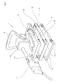
- FIG. 1 is to be taken from a manual tool 1, by which a sawing or milling disc 10, which is arranged in a housing 2, is to be driven.
- FIG. 2 It can be seen that with the help of the hand tool 1 plastered in a masonry 4 Metallklips 5 through which a window frame in the masonry opening is held, should be severed.
- the sawing or milling disc 10 is moved from an incorporated in the housing 2 outlet opening 3 in the direction of the metal clip 5.
- the manual working device 1 consists of two gripping pieces 7, to which a drive motor 8 is attached, through which a drive flange 9 arranged in the interior of the manual working device 1 is set in rotation.
- the sawing or milling disc 10 is drivingly coupled to the drive flange 9, so that the rotational force of the drive motor 8 is transmitted to the sawing or milling disc 10.
- one or more spacer plates 11 can be clipped to compensate for the distance between the bottom of the housing 2 and the window frame and adapt to the corresponding installation situations.
- the spacer plates 11 have different or equal sized wall thicknesses. If different thickness spacer plates 11 are present, the materials from which the spacer plates 11 are made, colored differently, so that the user can easily see from the color of the spacer plates 11, which wall thickness has the respective spacer plate 11.
- one or more receiving tables 12 made of a rigid material is worked on the housing 2, in the pin-like or web-like receiving chambers 13 which are incorporated in the spacer plate 11, and engage in the manner of Undercut in these are clipped or locked.
- the receiving pockets 12 and the receiving chamber 13 are positioned in the assembled state in alignment with each other and extend along the longitudinal side 6 of the housing 2, so as not to hinder the exit of the sawing or milling disc 10.
- the receiving chambers 13 are suspended in the receiving lugs 12, and about the axis of rotation formed in this way, the first spacer plate 11 is pivoted in the direction of the housing 2, so that one or more of the spacer plate 11 attached pin 14 pass in the direction of the housing 2, in which one or more receiving chambers 15 are incorporated.
- the pins 14 and the receiving chambers 15 are superimposed, the pins 14 are pressed outwards, until such time as the receiving chamber 15, the pins 14 releases so that they snap back due to their elastic deformability to its original position and the pin 14 in the manner of a Undercut is latched to the respective receiving chamber 15.
- receiving lugs 12 and receiving chambers 15 are also mounted opposite each other, so that the next second spacer plate 11 having identical structural design features as the first spacer plate 11 can be fixed in the same procedure to the first spacer plate 11 , Consequently, a plurality of spacer plates 11 are attached to the housing 2 and to each other, so that an arbitrary distance can be compensated.
- the geometric dimensions of the housing 2 and the spacer plates 11 are aligned with each other, so that no lateral projections arise.
- spacer plates 11 are mounted in the form of a three-point bearing on the housing 2, so that the further locking of adjacent spacer plates 11 takes place in the form of a three-point bearing to ensure that all spacer plates 11 directly to the bottom of the housing 2, as explained above , can be clipped.
Landscapes
- Engineering & Computer Science (AREA)
- Mechanical Engineering (AREA)
- Mining & Mineral Resources (AREA)
- Processing Of Stones Or Stones Resemblance Materials (AREA)
Abstract
Description
- Die Erfindung bezieht sich auf ein Handarbeitsgerät, das insbesondere zum Durchtrennen eines Metallklipses in einem Mauerwerk verwendbar ist, nach dem Oberbegriff des Schutzanspruches 1.
- Aus der DE-GM 2 990 944.9 ist ein solches Handarbeitsgerät bekannt geworden, das zum Heraustrennen von in Mauerwerken eingesetzten Fensterrahmen zu Renovierungszwecken verwendet werden kann. Die Fensterrahmen sind dabei mit Hilfe von einer Vielzahl von Metallklipsen mit dem Mauerwerk verbunden. Die Metallklipse sind verputzt, so dass die Säge- oder Frässcheibe des Handarbeitsgerätes sowohl das Mauerwerk als auch den Putz und den jeweiligen Metallklips zu durchtrennen hat. Sobald sämtliche Metallklipse zerschnitten sind, kann der Fensterrahmen ausgebaut werden.
- Da oftmals erhebliche Abstandsunterschiede zwischen dem Mauerwerk und dem Fensterrahmen zu überbrücken sind, werden unterschiedlich lang ausgestaltete Metallklipse beim Einbau der Fensterrahmen verwendet. Die Unterseite des Gehäuses des Handarbeitsgerätes dient als Auflagefläche auf dem Fensterrahmen zur Führung des Handarbeitsgerätes entlang der Stirnseite des Mauerwerkes. Wenn jedoch Abstandsunterschiede zwischen eingebauten und neu einzusetzenden Fensterrahmen vorliegen, ist ein Ausgleich vorzunehmen, um eine korrekte Montage des neuen Fensterrahmens im Mauerwerk zu ermöglichen.
- Der Benutzer des Handarbeitsgerätes hat folglich eine Vielzahl von unterschiedlich bemessenen Unterlagsscheiben, -Platten oder Leisten mitzuführen, die an der jeweiligen Bearbeitungsstelle an dem Fensterrahmen aufzusetzen sind, um das Handarbeitsgerät in richtigem Abstand zu führen.
- Eine solche Anwendung hat sich als äußerst zeitaufwändig und unprofessionell erwiesen, denn oftmals hat ein Benutzer nicht die notwendigen Unterlagsplatten dabei und/oder diese rutschen vom Fensterrahmen ab, so dass das Handarbeitsgerät nicht ordnungsgemäß geführt werden kann. Zudem benötigt der Benutzer beide Hände, um das Handarbeitsgerät zu halten, so dass die Unterlagsscheiben nicht oder von einer weiteren Person fixiert sind.
- Auch die stufenlose Herstellung der Unterseite des Gehäuses mittels Stellschrauben hat sich lediglich bedingt bewährt, denn die Einstellung der Stellschrauben ist exakt aufeinander abzustimmen und gegen einen bestimmten Drehwiderstand durchzuführen. Da oftmals in den Eckbereichen des Gehäuses diese Stellschrauben angeordnet sind, sind mehrere Stellschrauben zu verändern, um das Gehäuse an die unterschiedlichen vorliegenden Abstände anzupassen. Diese Einstellungsmöglichkeit hat sich daher als äußerst zeitaufwändig erwiesen.
- Es ist daher Aufgabe der Erfindung, ein Handarbeitsgerät der eingangs genannten Gattung bereit zu stellen, mittels dem das Heraustrennen von Fensterrahmen möglich ist, bei denen unterschiedliche geometrische Abstände zwischen der Auflagefläche des Handarbeitsgerätes und der Schnittfuge vorliegen, und solche Abstände auf schnelle und einfache Weise an dem Handarbeitsgerät variabel ausgleichbar sind.
- Diese Aufgabe ist erfindungsgemäß, durch die Merkmale des kennzeichnenden Teils von Schutzanspruch 1 gelöst.
- Weitere vorteilhafte Weiterbildungen der Erfindung ergeben sich aus den Unteransprüchen.
- Dadurch, dass an dem Gehäuse, in dem die Säge- oder Frässcheibe angeordnet ist, außenseitig eine oder mehrere Distanzplatten, die unterschiedlich groß bemessene
- Wandstärken aufweisen, angebracht werden können, ist der Abstand zwischen dem Fensterrahmen und der Schnittfuge variabel ausgleichbar, so dass das Handarbeitsgerät vorteilhafterweise an der Stirnseite des Mauerwerks exakt positioniert ist und geführt gehalten aufliegt. Zudem ist besonders vorteilhaft, dass die Distanzplatten schnell und einfach an das Gehäuse bzw. stapelbar aneinander angebracht werden können.
- Darüberhinaus kann der Benutzer des Handarbeitsgerätes anhand unterschiedlicher Farben von Distanzplatten erkennen, welche Wandstärke die jeweilige Distanzplatte aufweist, um einen optimalen Ausgleich vornehmen zu können.
- Da die Distanzplatte fest an der Unterseite des Gehäuses aufgebracht sind, die ganz oder teilweise plan ausgestaltet ist, um eine möglichst groß bemessene Auflagefläche bereitzustellen, verschieben sich die Distanzplatten nicht relativ gegenüber dem Gehäuse und auch nicht untereinander, so dass die Führung des Handarbeitsgerätes entlang des Mauerwerkes bewerkstelligt ist.
- In der Zeichnung ist ein erfindungsgemäßes Ausführungsbeispiel eines Handarbeitsgerätes dargestellt, das nachfolgend näher erläutert ist. Im Einzelnen zeigt:
- Figur 1
- ein Handarbeitsgerät mit einem Griffstück mit einem an diesem befestigten Antriebsmotor, der über einem Antriebsflansch trieblich mit einer Säge- oder Frässcheibe verbunden ist, mit einem Gehäuse, in dem die Säge- oder Frässcheibe angeordnet ist und mit einer an die Unterseite des Gehäuses einklipsbaren Distanzplatte, in perspektivischer Ansicht und
- Figur 2
- das Handarbeitsgerät gemäß
Figur 1 mit zwei an der Unterseite des Gehäuses angebrachten Distanzplatten, im Schnitt. - Aus
Figur 1 ist ein Handarbeitsgerät 1 zu entnehmen, durch das eine Säge- oder Frässcheibe 10, die in einem Gehäuse 2 angeordnet ist, anzutreiben ist. AusFigur 2 ist ersichtlich, dass mit Hilfe des Handarbeitsgerätes 1 ein in einem Mauerwerk 4 eingeputzter Metallklips 5, durch den ein Fensterrahmen in der Mauerwerköffnung gehalten ist, durchtrennt werden soll. Zu diesem Zweck wird die Säge- oder Frässcheibe 10 aus einer in dem Gehäuse 2 eingearbeiteten Austrittsöffnung 3 in Richtung des Metallklipses 5 verschoben. - Zudem besteht das Handarbeitsgerät 1 aus zwei Griffstücke 7, an denen ein Antriebsmotor 8 angebracht ist, durch den ein im Inneren des Handarbeitsgerätes 1 angeordnete Antriebsflansch 9 in Rotation versetzt ist. Die Säge- oder Frässcheibe 10 ist trieblich mit dem Antriebsflansch 9 gekoppelt, so dass die Rotationskraft des Antriebsmotors 8 auf die Säge- oder Frässcheibe 10 übertragen ist.
- Aus den
Figuren 1 und2 ist zu entnehmen, dass an die Unterseite des Gehäuses 2 eine oder mehrere Distanzplatten 11 angeklipst werden können, um den Abstand zwischen der Unterseite des Gehäuses 2 und dem Fensterrahmen auszugleichen und an die entsprechenden Einbausituationen anzupassen. - Die Distanzplatten 11 weisen unterschiedliche oder gleich groß bemessene Wandstärken auf. Wenn unterschiedlich dicke Distanzplatten 11 vorhanden sind, sind die Werkstoffe, aus denen die Distanzplatten 11 gefertigt sind, unterschiedlich eingefärbt, so dass der Benutzer anhand der Farbgebung der Distanzplatten 11 ohne weiteres erkennen kann, welche Wandstärke die jeweilige Distanzplatte 11 aufweist.
- Um die Distanzplatten 11 an die Unterseite des Gehäuses 2 anzubringen, ist an das Gehäuse 2 eine oder mehrere Aufnahmetischen 12 aus einem biegesteifen Werkstoff angearbeitet, in die zapfen- oder stegartige Aufnahmekammern 13, die in die Distanzplatte 11 eingearbeitet sind, eingreifen und nach Art einer Hinterschneidung in diesen eingeklipst bzw. arretiert sind. Die Aufnahmetaschen 12 und die Aufnahmekammer 13 sind im montiertem Zustand fluchtend zueinander positioniert und verlaufen entlang der Längsseite 6 des Gehäuses 2, um den Austritt der Säge- oder Frässcheibe 10 nicht zu behindern.
- Zur Montage bzw. Demontage der ersten benachbart zu dem Gehäuse 2 angeordneten Distanzplatte 11 werden die Aufnahmekammern 13 in die Aufnahmelaschen 12 eingehängt, und um die derart gebildete Drehachse wird die erste Distanzplatte 11 in Richtung des Gehäuses 2 verschwenkt, so dass ein oder mehrere an der Distanzplatte 11 angebrachten Zapfen 14 in Richtung des Gehäuses 2 gelangen, in dem eine oder mehrere Aufnahmekammern 15 eingearbeitet sind. Sobald die Zapfen 14 und die Aufnahmekammern 15 übereinander liegen, werden die Zapfen 14 nach außen gedrückt, und zwar solange, bis die Aufnahmekammer 15 die Zapfen 14 freigibt, so dass diese aufgrund ihrer elastischen Verformbarkeit in ihre Ausgangsposition zurückschnappen und die Zapfen 14 nach Art einer Hinterschneidung an der jeweiligen Aufnahmekammer 15 verrastet ist.
- An der an dem Gehäuse 2 angebrachten Distanzplatte 11 sind ebenfalls Aufnahmelaschen 12 und Aufnahmekammern 15 gegenüberliegend zueinander angebracht, so dass die nächste zweite Distanzplatte 11, die identische konstruktive Ausgestaltungsmerkmale wie die erste Distanzplatte 11 aufweist, in gleicher Verfahrensweise an die erste Distanzplatte 11 befestigt werden kann. Folglich sind eine Vielzahl von Distanzplatten 11 an das Gehäuse 2 bzw. aneinanderliegend angebracht, so dass ein beliebiger Abstand ausgeglichen werden kann.
- Vorteilhafterweise sind die geometrischen Abmessungen des Gehäuses 2 und der Distanzplatten 11 fluchtend zueinander ausgestaltet, so dass keine seitlichen Überstände entstehen.
- Da solche Handarbeitsgeräte 1 auch eine ausschwenkbare Säge- oder Frässcheibe 10 tragen können, ist es erforderlich, im vorderen Eckbereich des Gehäuses 2 die Arretierungsmöglichkeiten zwischen dem Gehäuse 2 und der ersten Distanzplatte 11 zu entfernen, um die Verschwenkbewegung der Säge- oder Frässcheibe 10 nicht zu behindern. Somit sind die Distanzplatten 11 in Form einer Dreipunktlagerung an dem Gehäuse 2 anzubringen, so dass auch die weitere Arretierung von benachbarten Distanzplatten 11 in Form einer Dreipunktlagerung erfolgt, um zu gewährleisten, dass sämtliche Distanzplatten 11 unmittelbar an die Unterseite des Gehäuses 2, wie vorstehend erläutert, angeklipst werden können.
Claims (9)
- Handarbeitsgerät (1), insbesondere zum Durchtrennen eines Metallklipses (5) in einem Mauerwerk (4), mit einer Säge- oder Frässcheibe (10), die über einen Antriebsflansch (9) mit einem Antriebsmotor (8) des Handarbeitsgerätes (1) trieblich verbunden ist, mit einem an dem Handarbeitsgerät (1) befestigten Gehäuse (2), in dem die Säge- oder Frässcheibe (10) angeordnet ist, in dessen dem Metallklips (5) zugewandten Stirnseite eine Austrittsöffnung (3) für den Austritt der Säge- oder Frässcheibe (10) vorgesehen ist, durch die die Säge- oder Frässcheibe (10), zumindest teilweise, aus dem Gehäuse (2) ragt,
dadurch gekennzeichnet,
dass die Unterseite des Gehäuses (2) ganz oder teilweise plan ausgestaltet ist, dass an der Unterseite des Gehäuses (2) mindestens eine Distanzplatte (11) mit einer vorgegebenen Wandstärke befestigbar ist und dass durch die Distanzplatte (11) der Abstand zwischen der Säge- oder Frässcheibe (10) und dem Mauerwerk (4) einstellbar ist. - Handarbeitsgerät nach Anspruch 1,
dadurch gekennzeichnet
dass an dem Gehäuse (2) mindestens eine zapfen- oder stegförmige Aufnahmelasche (12) vorgesehen ist, in die eine in die Distanzplatte (11) eingearbeitete Aufnahmekammer (13) nach Art einer Hinterschneidung verrastbar ist und/oder dass an der Distanzplatte (11) mindestens ein biegeelastischer Zapfen (14) angeformt ist, der in eine in das Gehäuse (2) des Handarbeitsgerätes (1) eingeformte Aufnahmekammer (15) nach Art einer Hinterschneidung verrastbar oder verklipsbar gehalten ist. - Handarbeitsgerät nach Anspruch 2,
dadurch gekennzeichnet,
dass die Aufnahmetaschen (12) an dem Gehäuse (2) und die Aufnahmekammern (13) an der Distanzplatte (11) bzw. die Zapfen (14) an der Distanzplatte (11) und den Aufnahmekammern (13) an dem Gehäuse (2) im montiertem Zustand fluchtend zueinander verlaufen. - Handarbeitsgerät nach Anspruch 2 oder 3,
dadurch gekennzeichnet,
dass die Aufnahmetaschen (12) an dem Gehäuse (2) und die Aufnahmekammern (13) an der Distanzplatte (11) bzw. die Zapfen (14) an der Distanzplatte (11) und die Aufnahmekammern (15) an dem Gehäuse (2) an den beiden Längsseiten (6) des Handarbeitsgerätes (1) angeordnet sind. - Handarbeitsgerät nach einem der vorgenannten Ansprüche,
dadurch gekennzeichnet,
dass an jeder der Distanzplatte (11) ein oder mehrere Aufnahmelaschen (12) angeformt bzw. angebracht ist bzw. sind, die in Aufnahmekammern (13) einer benachbart anzuordnenden Distanzplatte (11) nach Art einer Hinterschneidung einrastbar sind und dass an der benachbarten zweiten Distanzplatte (11) Zapfen (14) angeformt sind, die jeweils in eine Aufnahmekammer (13), die in der ersten Distanzplatte (11) eingearbeitet ist, verklipsbar ist. - Handarbeitsgerät nach Anspruch 5,
dadurch gekennzeichnet,
dass eine Vielzahl von Distanzplatten (11) stapelbar übereinander angeordnet sind und dass die jeweiligen Distanzplatten (11) identische und/oder unterschiedliche Wandstärken aufweisen. - Handarbeitsgerät nach einem der vorgenannten Ansprüche,
dadurch gekennzeichnet,
dass die Distanzplatten (11) mit unterschiedlichen Wandstärken aus einem farblich andersartigen Werkstoff hergestellt sind. - Handarbeitsgerät nach einem der vorgenannten Ansprüche,
dadurch gekennzeichnet,
dass die Aufnahmetasche (12); die Aufnahmekammern (13, 15) und die Zapfen (14) zwischen dem Gehäuse (2) und der ersten Distanzplatte (11) sowie zwischen zwei benachbarten Distanzplatten (11) als Dreipunktlagerung miteinander arretiert sind. - Handarbeitsgerät nach einem der vorgenannten Ansprüche,
dadurch gekennzeichnet,
dass die Abmessungen des Gehäuses (2) und der Distanzplatten (11) fluchtend zueinander ausgestaltet ist.
Applications Claiming Priority (1)
| Application Number | Priority Date | Filing Date | Title |
|---|---|---|---|
| DE201220002727 DE202012002727U1 (de) | 2012-03-19 | 2012-03-19 | Handarbeitsgerät |
Publications (2)
| Publication Number | Publication Date |
|---|---|
| EP2641684A1 true EP2641684A1 (de) | 2013-09-25 |
| EP2641684B1 EP2641684B1 (de) | 2017-04-19 |
Family
ID=46083352
Family Applications (1)
| Application Number | Title | Priority Date | Filing Date |
|---|---|---|---|
| EP13150540.6A Active EP2641684B1 (de) | 2012-03-19 | 2013-01-08 | Handarbeitsgerät |
Country Status (2)
| Country | Link |
|---|---|
| EP (1) | EP2641684B1 (de) |
| DE (1) | DE202012002727U1 (de) |
Cited By (1)
| Publication number | Priority date | Publication date | Assignee | Title |
|---|---|---|---|---|
| CN104874509A (zh) * | 2015-05-21 | 2015-09-02 | 西安航空动力股份有限公司 | 一种涡轮导向叶片自动化喷涂支撑保护夹具 |
Families Citing this family (1)
| Publication number | Priority date | Publication date | Assignee | Title |
|---|---|---|---|---|
| DE102016109049A1 (de) * | 2016-05-17 | 2017-11-23 | Eberhard Berhalter | Handwerkzeugmaschinenvorrichtung zu einer beweglichen Lagerung einer Welle in einer Führungsbahn |
Citations (4)
| Publication number | Priority date | Publication date | Assignee | Title |
|---|---|---|---|---|
| DE498645C (de) * | 1929-02-14 | 1930-05-24 | Gustav Flebbe | Vorrichtung zur Herstellung von Nuten, Rillen oder aehnlichen Vertiefungen in Steinen, Mauerwerk o. dgl. |
| GB2309411A (en) * | 1996-01-23 | 1997-07-30 | Chi Pin Lee | Mortise making attachment for a machine tool |
| US6112736A (en) * | 1991-12-06 | 2000-09-05 | Bearden; Martin A. | Portable saw with improved disconnectable platform for cutting concrete for controlling cracks |
| DE202008013556U1 (de) * | 2008-10-15 | 2009-02-26 | Popp, Siegfried | Höhenverstellung für eine Schutz- oder Führungseinrichtung für ein Trenn- oder Schleifgerät |
-
2012
- 2012-03-19 DE DE201220002727 patent/DE202012002727U1/de not_active Expired - Lifetime
-
2013
- 2013-01-08 EP EP13150540.6A patent/EP2641684B1/de active Active
Patent Citations (4)
| Publication number | Priority date | Publication date | Assignee | Title |
|---|---|---|---|---|
| DE498645C (de) * | 1929-02-14 | 1930-05-24 | Gustav Flebbe | Vorrichtung zur Herstellung von Nuten, Rillen oder aehnlichen Vertiefungen in Steinen, Mauerwerk o. dgl. |
| US6112736A (en) * | 1991-12-06 | 2000-09-05 | Bearden; Martin A. | Portable saw with improved disconnectable platform for cutting concrete for controlling cracks |
| GB2309411A (en) * | 1996-01-23 | 1997-07-30 | Chi Pin Lee | Mortise making attachment for a machine tool |
| DE202008013556U1 (de) * | 2008-10-15 | 2009-02-26 | Popp, Siegfried | Höhenverstellung für eine Schutz- oder Führungseinrichtung für ein Trenn- oder Schleifgerät |
Cited By (2)
| Publication number | Priority date | Publication date | Assignee | Title |
|---|---|---|---|---|
| CN104874509A (zh) * | 2015-05-21 | 2015-09-02 | 西安航空动力股份有限公司 | 一种涡轮导向叶片自动化喷涂支撑保护夹具 |
| CN104874509B (zh) * | 2015-05-21 | 2017-04-19 | 西安航空动力股份有限公司 | 一种涡轮导向叶片自动化喷涂支撑保护夹具 |
Also Published As
| Publication number | Publication date |
|---|---|
| DE202012002727U1 (de) | 2012-04-13 |
| EP2641684B1 (de) | 2017-04-19 |
Similar Documents
| Publication | Publication Date | Title |
|---|---|---|
| EP2807002A1 (de) | Schneidwerkzeug | |
| DE102005000143A1 (de) | Abdeckvorrichtung | |
| EP3357646A2 (de) | Elektrohandwerkzeug mit staubschutz-abdeckung | |
| DE202019105044U1 (de) | Schutzabdeckung zur Abdeckung von beweglichen Maschinenteilen oder dergleichen | |
| EP2641684B1 (de) | Handarbeitsgerät | |
| DE102015119431B4 (de) | Lochsäge | |
| EP2849907B1 (de) | Vorrichtung zum fixieren eines mittels einer bearbeitungsmaschine zu bearbeitenden werkstücks | |
| DE102014113114B4 (de) | Teleskopische Schutzabdeckung | |
| DE2945749C2 (de) | Wandanschlußstück | |
| DE102017124413B4 (de) | Bohrschablone und Verfahren zum Markieren oder Anbohren zweier Möbelplatten | |
| EP0133197A1 (de) | Hobelwerkzeug und dafür geeignetes Profilmesser | |
| DE10258567B4 (de) | Vorrichtung zur Stanzbearbeitung einer Leiste, insbesondere einer Sockelleiste | |
| EP1059140B1 (de) | Handarbeitsgerät | |
| DE102009050134A1 (de) | Verbindungen von Führungsschienen | |
| DE910589C (de) | Anordnung zur Befestigung von Schutzgittern u. dgl. | |
| EP2363242B1 (de) | Handarbeitsgerät | |
| DE10116322C2 (de) | Verbindungselement für Profilleisten sowie daraus hergestellte Rahmenanordnung für den Trockenbau | |
| EP3815845B1 (de) | Spannvorrichtung zum einspannen eines werkstücks | |
| EP1358978B1 (de) | Vorrichtung zur Stanzbearbeitung einer Sockelleiste, insbesondere Kernsockelleiste | |
| EP3823787B1 (de) | Vorrichtung zum stützen und/oder führen einer werkzeugmaschine | |
| DE9413470U1 (de) | Bohrlehre | |
| DE202004000359U1 (de) | Hilfsvorrichtung zum Bearbeiten eines Werkstückes | |
| DE4013050A1 (de) | Messerkopf und hobelwelle fuer abrichte-, dicken- und/oder hand- bzw. heimwerker-hobelmaschinen | |
| DE20316190U1 (de) | Vorrichtung zum lösbaren Befestigen elektrisch betriebener Werkzeugmaschinen | |
| EP3555396B1 (de) | Befestigungssystem |
Legal Events
| Date | Code | Title | Description |
|---|---|---|---|
| PUAI | Public reference made under article 153(3) epc to a published international application that has entered the european phase |
Free format text: ORIGINAL CODE: 0009012 |
|
| AK | Designated contracting states |
Kind code of ref document: A1 Designated state(s): AL AT BE BG CH CY CZ DE DK EE ES FI FR GB GR HR HU IE IS IT LI LT LU LV MC MK MT NL NO PL PT RO RS SE SI SK SM TR |
|
| AX | Request for extension of the european patent |
Extension state: BA ME |
|
| 17P | Request for examination filed |
Effective date: 20140204 |
|
| RBV | Designated contracting states (corrected) |
Designated state(s): AL AT BE BG CH CY CZ DE DK EE ES FI FR GB GR HR HU IE IS IT LI LT LU LV MC MK MT NL NO PL PT RO RS SE SI SK SM TR |
|
| 17Q | First examination report despatched |
Effective date: 20151126 |
|
| GRAP | Despatch of communication of intention to grant a patent |
Free format text: ORIGINAL CODE: EPIDOSNIGR1 |
|
| STAA | Information on the status of an ep patent application or granted ep patent |
Free format text: STATUS: GRANT OF PATENT IS INTENDED |
|
| INTG | Intention to grant announced |
Effective date: 20161116 |
|
| GRAS | Grant fee paid |
Free format text: ORIGINAL CODE: EPIDOSNIGR3 |
|
| GRAA | (expected) grant |
Free format text: ORIGINAL CODE: 0009210 |
|
| STAA | Information on the status of an ep patent application or granted ep patent |
Free format text: STATUS: THE PATENT HAS BEEN GRANTED |
|
| AK | Designated contracting states |
Kind code of ref document: B1 Designated state(s): AL AT BE BG CH CY CZ DE DK EE ES FI FR GB GR HR HU IE IS IT LI LT LU LV MC MK MT NL NO PL PT RO RS SE SI SK SM TR |
|
| REG | Reference to a national code |
Ref country code: GB Ref legal event code: FG4D Free format text: NOT ENGLISH |
|
| REG | Reference to a national code |
Ref country code: CH Ref legal event code: EP |
|
| REG | Reference to a national code |
Ref country code: AT Ref legal event code: REF Ref document number: 885476 Country of ref document: AT Kind code of ref document: T Effective date: 20170515 |
|
| REG | Reference to a national code |
Ref country code: IE Ref legal event code: FG4D Free format text: LANGUAGE OF EP DOCUMENT: GERMAN |
|
| REG | Reference to a national code |
Ref country code: DE Ref legal event code: R096 Ref document number: 502013006985 Country of ref document: DE |
|
| REG | Reference to a national code |
Ref country code: CH Ref legal event code: NV Representative=s name: PATENTANWALTSKANZLEI DAUB, CH |
|
| REG | Reference to a national code |
Ref country code: NL Ref legal event code: MP Effective date: 20170419 |
|
| REG | Reference to a national code |
Ref country code: LT Ref legal event code: MG4D |
|
| PG25 | Lapsed in a contracting state [announced via postgrant information from national office to epo] |
Ref country code: NL Free format text: LAPSE BECAUSE OF FAILURE TO SUBMIT A TRANSLATION OF THE DESCRIPTION OR TO PAY THE FEE WITHIN THE PRESCRIBED TIME-LIMIT Effective date: 20170419 |
|
| PG25 | Lapsed in a contracting state [announced via postgrant information from national office to epo] |
Ref country code: ES Free format text: LAPSE BECAUSE OF FAILURE TO SUBMIT A TRANSLATION OF THE DESCRIPTION OR TO PAY THE FEE WITHIN THE PRESCRIBED TIME-LIMIT Effective date: 20170419 Ref country code: HR Free format text: LAPSE BECAUSE OF FAILURE TO SUBMIT A TRANSLATION OF THE DESCRIPTION OR TO PAY THE FEE WITHIN THE PRESCRIBED TIME-LIMIT Effective date: 20170419 Ref country code: NO Free format text: LAPSE BECAUSE OF FAILURE TO SUBMIT A TRANSLATION OF THE DESCRIPTION OR TO PAY THE FEE WITHIN THE PRESCRIBED TIME-LIMIT Effective date: 20170719 Ref country code: GR Free format text: LAPSE BECAUSE OF FAILURE TO SUBMIT A TRANSLATION OF THE DESCRIPTION OR TO PAY THE FEE WITHIN THE PRESCRIBED TIME-LIMIT Effective date: 20170720 Ref country code: FI Free format text: LAPSE BECAUSE OF FAILURE TO SUBMIT A TRANSLATION OF THE DESCRIPTION OR TO PAY THE FEE WITHIN THE PRESCRIBED TIME-LIMIT Effective date: 20170419 Ref country code: LT Free format text: LAPSE BECAUSE OF FAILURE TO SUBMIT A TRANSLATION OF THE DESCRIPTION OR TO PAY THE FEE WITHIN THE PRESCRIBED TIME-LIMIT Effective date: 20170419 |
|
| PG25 | Lapsed in a contracting state [announced via postgrant information from national office to epo] |
Ref country code: SE Free format text: LAPSE BECAUSE OF FAILURE TO SUBMIT A TRANSLATION OF THE DESCRIPTION OR TO PAY THE FEE WITHIN THE PRESCRIBED TIME-LIMIT Effective date: 20170419 Ref country code: IS Free format text: LAPSE BECAUSE OF FAILURE TO SUBMIT A TRANSLATION OF THE DESCRIPTION OR TO PAY THE FEE WITHIN THE PRESCRIBED TIME-LIMIT Effective date: 20170819 Ref country code: PL Free format text: LAPSE BECAUSE OF FAILURE TO SUBMIT A TRANSLATION OF THE DESCRIPTION OR TO PAY THE FEE WITHIN THE PRESCRIBED TIME-LIMIT Effective date: 20170419 Ref country code: BG Free format text: LAPSE BECAUSE OF FAILURE TO SUBMIT A TRANSLATION OF THE DESCRIPTION OR TO PAY THE FEE WITHIN THE PRESCRIBED TIME-LIMIT Effective date: 20170719 Ref country code: LV Free format text: LAPSE BECAUSE OF FAILURE TO SUBMIT A TRANSLATION OF THE DESCRIPTION OR TO PAY THE FEE WITHIN THE PRESCRIBED TIME-LIMIT Effective date: 20170419 Ref country code: RS Free format text: LAPSE BECAUSE OF FAILURE TO SUBMIT A TRANSLATION OF THE DESCRIPTION OR TO PAY THE FEE WITHIN THE PRESCRIBED TIME-LIMIT Effective date: 20170419 |
|
| REG | Reference to a national code |
Ref country code: DE Ref legal event code: R097 Ref document number: 502013006985 Country of ref document: DE |
|
| REG | Reference to a national code |
Ref country code: FR Ref legal event code: PLFP Year of fee payment: 6 |
|
| PG25 | Lapsed in a contracting state [announced via postgrant information from national office to epo] |
Ref country code: EE Free format text: LAPSE BECAUSE OF FAILURE TO SUBMIT A TRANSLATION OF THE DESCRIPTION OR TO PAY THE FEE WITHIN THE PRESCRIBED TIME-LIMIT Effective date: 20170419 Ref country code: CZ Free format text: LAPSE BECAUSE OF FAILURE TO SUBMIT A TRANSLATION OF THE DESCRIPTION OR TO PAY THE FEE WITHIN THE PRESCRIBED TIME-LIMIT Effective date: 20170419 Ref country code: DK Free format text: LAPSE BECAUSE OF FAILURE TO SUBMIT A TRANSLATION OF THE DESCRIPTION OR TO PAY THE FEE WITHIN THE PRESCRIBED TIME-LIMIT Effective date: 20170419 Ref country code: SK Free format text: LAPSE BECAUSE OF FAILURE TO SUBMIT A TRANSLATION OF THE DESCRIPTION OR TO PAY THE FEE WITHIN THE PRESCRIBED TIME-LIMIT Effective date: 20170419 Ref country code: RO Free format text: LAPSE BECAUSE OF FAILURE TO SUBMIT A TRANSLATION OF THE DESCRIPTION OR TO PAY THE FEE WITHIN THE PRESCRIBED TIME-LIMIT Effective date: 20170419 |
|
| PLBE | No opposition filed within time limit |
Free format text: ORIGINAL CODE: 0009261 |
|
| STAA | Information on the status of an ep patent application or granted ep patent |
Free format text: STATUS: NO OPPOSITION FILED WITHIN TIME LIMIT |
|
| PG25 | Lapsed in a contracting state [announced via postgrant information from national office to epo] |
Ref country code: IT Free format text: LAPSE BECAUSE OF FAILURE TO SUBMIT A TRANSLATION OF THE DESCRIPTION OR TO PAY THE FEE WITHIN THE PRESCRIBED TIME-LIMIT Effective date: 20170419 Ref country code: SM Free format text: LAPSE BECAUSE OF FAILURE TO SUBMIT A TRANSLATION OF THE DESCRIPTION OR TO PAY THE FEE WITHIN THE PRESCRIBED TIME-LIMIT Effective date: 20170419 |
|
| 26N | No opposition filed |
Effective date: 20180122 |
|
| PG25 | Lapsed in a contracting state [announced via postgrant information from national office to epo] |
Ref country code: SI Free format text: LAPSE BECAUSE OF FAILURE TO SUBMIT A TRANSLATION OF THE DESCRIPTION OR TO PAY THE FEE WITHIN THE PRESCRIBED TIME-LIMIT Effective date: 20170419 |
|
| PG25 | Lapsed in a contracting state [announced via postgrant information from national office to epo] |
Ref country code: MT Free format text: LAPSE BECAUSE OF FAILURE TO SUBMIT A TRANSLATION OF THE DESCRIPTION OR TO PAY THE FEE WITHIN THE PRESCRIBED TIME-LIMIT Effective date: 20170419 |
|
| PG25 | Lapsed in a contracting state [announced via postgrant information from national office to epo] |
Ref country code: LU Free format text: LAPSE BECAUSE OF NON-PAYMENT OF DUE FEES Effective date: 20180108 |
|
| REG | Reference to a national code |
Ref country code: IE Ref legal event code: MM4A |
|
| REG | Reference to a national code |
Ref country code: BE Ref legal event code: MM Effective date: 20180131 |
|
| PG25 | Lapsed in a contracting state [announced via postgrant information from national office to epo] |
Ref country code: BE Free format text: LAPSE BECAUSE OF NON-PAYMENT OF DUE FEES Effective date: 20180131 |
|
| PG25 | Lapsed in a contracting state [announced via postgrant information from national office to epo] |
Ref country code: IE Free format text: LAPSE BECAUSE OF NON-PAYMENT OF DUE FEES Effective date: 20180108 |
|
| REG | Reference to a national code |
Ref country code: CH Ref legal event code: PCAR Free format text: NEW ADDRESS: LEUTSCHENBACHSTRASSE 95, 8050 ZUERICH (CH) |
|
| PG25 | Lapsed in a contracting state [announced via postgrant information from national office to epo] |
Ref country code: MC Free format text: LAPSE BECAUSE OF FAILURE TO SUBMIT A TRANSLATION OF THE DESCRIPTION OR TO PAY THE FEE WITHIN THE PRESCRIBED TIME-LIMIT Effective date: 20170419 |
|
| PG25 | Lapsed in a contracting state [announced via postgrant information from national office to epo] |
Ref country code: TR Free format text: LAPSE BECAUSE OF FAILURE TO SUBMIT A TRANSLATION OF THE DESCRIPTION OR TO PAY THE FEE WITHIN THE PRESCRIBED TIME-LIMIT Effective date: 20170419 |
|
| PG25 | Lapsed in a contracting state [announced via postgrant information from national office to epo] |
Ref country code: PT Free format text: LAPSE BECAUSE OF FAILURE TO SUBMIT A TRANSLATION OF THE DESCRIPTION OR TO PAY THE FEE WITHIN THE PRESCRIBED TIME-LIMIT Effective date: 20170419 Ref country code: HU Free format text: LAPSE BECAUSE OF FAILURE TO SUBMIT A TRANSLATION OF THE DESCRIPTION OR TO PAY THE FEE WITHIN THE PRESCRIBED TIME-LIMIT; INVALID AB INITIO Effective date: 20130108 |
|
| PG25 | Lapsed in a contracting state [announced via postgrant information from national office to epo] |
Ref country code: CY Free format text: LAPSE BECAUSE OF FAILURE TO SUBMIT A TRANSLATION OF THE DESCRIPTION OR TO PAY THE FEE WITHIN THE PRESCRIBED TIME-LIMIT Effective date: 20170419 Ref country code: MK Free format text: LAPSE BECAUSE OF NON-PAYMENT OF DUE FEES Effective date: 20170419 |
|
| PG25 | Lapsed in a contracting state [announced via postgrant information from national office to epo] |
Ref country code: AL Free format text: LAPSE BECAUSE OF FAILURE TO SUBMIT A TRANSLATION OF THE DESCRIPTION OR TO PAY THE FEE WITHIN THE PRESCRIBED TIME-LIMIT Effective date: 20170419 |
|
| P01 | Opt-out of the competence of the unified patent court (upc) registered |
Effective date: 20230522 |
|
| REG | Reference to a national code |
Ref country code: CH Ref legal event code: U11 Free format text: ST27 STATUS EVENT CODE: U-0-0-U10-U11 (AS PROVIDED BY THE NATIONAL OFFICE) Effective date: 20260201 |
|
| PGFP | Annual fee paid to national office [announced via postgrant information from national office to epo] |
Ref country code: GB Payment date: 20260122 Year of fee payment: 14 |
|
| PGFP | Annual fee paid to national office [announced via postgrant information from national office to epo] |
Ref country code: DE Payment date: 20260120 Year of fee payment: 14 |
|
| PGFP | Annual fee paid to national office [announced via postgrant information from national office to epo] |
Ref country code: AT Payment date: 20260119 Year of fee payment: 14 |
|
| PGFP | Annual fee paid to national office [announced via postgrant information from national office to epo] |
Ref country code: FR Payment date: 20260128 Year of fee payment: 14 |
|
| PGFP | Annual fee paid to national office [announced via postgrant information from national office to epo] |
Ref country code: CH Payment date: 20260201 Year of fee payment: 14 |