EP2363282A2 - Matière composite en plusieurs couches composites fibreuses et dotée d'une zone de renforcement - Google Patents
Matière composite en plusieurs couches composites fibreuses et dotée d'une zone de renforcement Download PDFInfo
- Publication number
- EP2363282A2 EP2363282A2 EP11156210A EP11156210A EP2363282A2 EP 2363282 A2 EP2363282 A2 EP 2363282A2 EP 11156210 A EP11156210 A EP 11156210A EP 11156210 A EP11156210 A EP 11156210A EP 2363282 A2 EP2363282 A2 EP 2363282A2
- Authority
- EP
- European Patent Office
- Prior art keywords
- layers
- fiber composite
- reinforcing
- perforations
- composite
- Prior art date
- Legal status (The legal status is an assumption and is not a legal conclusion. Google has not performed a legal analysis and makes no representation as to the accuracy of the status listed.)
- Granted
Links
Images



Classifications
-
- B—PERFORMING OPERATIONS; TRANSPORTING
- B32—LAYERED PRODUCTS
- B32B—LAYERED PRODUCTS, i.e. PRODUCTS BUILT-UP OF STRATA OF FLAT OR NON-FLAT, e.g. CELLULAR OR HONEYCOMB, FORM
- B32B5/00—Layered products characterised by the non- homogeneity or physical structure, i.e. comprising a fibrous, filamentary, particulate or foam layer; Layered products characterised by having a layer differing constitutionally or physically in different parts
- B32B5/22—Layered products characterised by the non- homogeneity or physical structure, i.e. comprising a fibrous, filamentary, particulate or foam layer; Layered products characterised by having a layer differing constitutionally or physically in different parts characterised by the presence of two or more layers which are next to each other and are fibrous, filamentary, formed of particles or foamed
- B32B5/24—Layered products characterised by the non- homogeneity or physical structure, i.e. comprising a fibrous, filamentary, particulate or foam layer; Layered products characterised by having a layer differing constitutionally or physically in different parts characterised by the presence of two or more layers which are next to each other and are fibrous, filamentary, formed of particles or foamed one layer being a fibrous or filamentary layer
- B32B5/26—Layered products characterised by the non- homogeneity or physical structure, i.e. comprising a fibrous, filamentary, particulate or foam layer; Layered products characterised by having a layer differing constitutionally or physically in different parts characterised by the presence of two or more layers which are next to each other and are fibrous, filamentary, formed of particles or foamed one layer being a fibrous or filamentary layer another layer next to it also being fibrous or filamentary
-
- B—PERFORMING OPERATIONS; TRANSPORTING
- B29—WORKING OF PLASTICS; WORKING OF SUBSTANCES IN A PLASTIC STATE IN GENERAL
- B29C—SHAPING OR JOINING OF PLASTICS; SHAPING OF MATERIAL IN A PLASTIC STATE, NOT OTHERWISE PROVIDED FOR; AFTER-TREATMENT OF THE SHAPED PRODUCTS, e.g. REPAIRING
- B29C37/00—Component parts, details, accessories or auxiliary operations, not covered by group B29C33/00 or B29C35/00
- B29C37/0078—Measures or configurations for obtaining anchoring effects in the contact areas between layers
- B29C37/0082—Mechanical anchoring
- B29C37/0085—Mechanical anchoring by means of openings in the layers
-
- B—PERFORMING OPERATIONS; TRANSPORTING
- B29—WORKING OF PLASTICS; WORKING OF SUBSTANCES IN A PLASTIC STATE IN GENERAL
- B29C—SHAPING OR JOINING OF PLASTICS; SHAPING OF MATERIAL IN A PLASTIC STATE, NOT OTHERWISE PROVIDED FOR; AFTER-TREATMENT OF THE SHAPED PRODUCTS, e.g. REPAIRING
- B29C70/00—Shaping composites, i.e. plastics material comprising reinforcements, fillers or preformed parts, e.g. inserts
- B29C70/04—Shaping composites, i.e. plastics material comprising reinforcements, fillers or preformed parts, e.g. inserts comprising reinforcements only, e.g. self-reinforcing plastics
- B29C70/28—Shaping operations therefor
- B29C70/30—Shaping by lay-up, i.e. applying fibres, tape or broadsheet on a mould, former or core; Shaping by spray-up, i.e. spraying of fibres on a mould, former or core
- B29C70/304—In-plane lamination by juxtaposing or interleaving of plies, e.g. scarf joining
-
- B—PERFORMING OPERATIONS; TRANSPORTING
- B29—WORKING OF PLASTICS; WORKING OF SUBSTANCES IN A PLASTIC STATE IN GENERAL
- B29C—SHAPING OR JOINING OF PLASTICS; SHAPING OF MATERIAL IN A PLASTIC STATE, NOT OTHERWISE PROVIDED FOR; AFTER-TREATMENT OF THE SHAPED PRODUCTS, e.g. REPAIRING
- B29C70/00—Shaping composites, i.e. plastics material comprising reinforcements, fillers or preformed parts, e.g. inserts
- B29C70/68—Shaping composites, i.e. plastics material comprising reinforcements, fillers or preformed parts, e.g. inserts by incorporating or moulding on preformed parts, e.g. inserts or layers, e.g. foam blocks
- B29C70/86—Incorporated in coherent impregnated reinforcing layers, e.g. by winding
-
- B—PERFORMING OPERATIONS; TRANSPORTING
- B29—WORKING OF PLASTICS; WORKING OF SUBSTANCES IN A PLASTIC STATE IN GENERAL
- B29C—SHAPING OR JOINING OF PLASTICS; SHAPING OF MATERIAL IN A PLASTIC STATE, NOT OTHERWISE PROVIDED FOR; AFTER-TREATMENT OF THE SHAPED PRODUCTS, e.g. REPAIRING
- B29C70/00—Shaping composites, i.e. plastics material comprising reinforcements, fillers or preformed parts, e.g. inserts
- B29C70/88—Shaping composites, i.e. plastics material comprising reinforcements, fillers or preformed parts, e.g. inserts characterised primarily by possessing specific properties, e.g. electrically conductive or locally reinforced
-
- B—PERFORMING OPERATIONS; TRANSPORTING
- B32—LAYERED PRODUCTS
- B32B—LAYERED PRODUCTS, i.e. PRODUCTS BUILT-UP OF STRATA OF FLAT OR NON-FLAT, e.g. CELLULAR OR HONEYCOMB, FORM
- B32B15/00—Layered products comprising a layer of metal
- B32B15/14—Layered products comprising a layer of metal next to a fibrous or filamentary layer
-
- B—PERFORMING OPERATIONS; TRANSPORTING
- B32—LAYERED PRODUCTS
- B32B—LAYERED PRODUCTS, i.e. PRODUCTS BUILT-UP OF STRATA OF FLAT OR NON-FLAT, e.g. CELLULAR OR HONEYCOMB, FORM
- B32B3/00—Layered products comprising a layer with external or internal discontinuities or unevennesses, or a layer of non-planar shape; Layered products comprising a layer having particular features of form
- B32B3/10—Layered products comprising a layer with external or internal discontinuities or unevennesses, or a layer of non-planar shape; Layered products comprising a layer having particular features of form characterised by a discontinuous layer, i.e. formed of separate pieces of material
-
- B—PERFORMING OPERATIONS; TRANSPORTING
- B32—LAYERED PRODUCTS
- B32B—LAYERED PRODUCTS, i.e. PRODUCTS BUILT-UP OF STRATA OF FLAT OR NON-FLAT, e.g. CELLULAR OR HONEYCOMB, FORM
- B32B3/00—Layered products comprising a layer with external or internal discontinuities or unevennesses, or a layer of non-planar shape; Layered products comprising a layer having particular features of form
- B32B3/26—Layered products comprising a layer with external or internal discontinuities or unevennesses, or a layer of non-planar shape; Layered products comprising a layer having particular features of form characterised by a particular shape of the outline of the cross-section of a continuous layer; characterised by a layer with cavities or internal voids ; characterised by an apertured layer
- B32B3/266—Layered products comprising a layer with external or internal discontinuities or unevennesses, or a layer of non-planar shape; Layered products comprising a layer having particular features of form characterised by a particular shape of the outline of the cross-section of a continuous layer; characterised by a layer with cavities or internal voids ; characterised by an apertured layer characterised by an apertured layer, the apertures going through the whole thickness of the layer, e.g. expanded metal, perforated layer, slit layer regular cells B32B3/12
-
- B—PERFORMING OPERATIONS; TRANSPORTING
- B32—LAYERED PRODUCTS
- B32B—LAYERED PRODUCTS, i.e. PRODUCTS BUILT-UP OF STRATA OF FLAT OR NON-FLAT, e.g. CELLULAR OR HONEYCOMB, FORM
- B32B5/00—Layered products characterised by the non- homogeneity or physical structure, i.e. comprising a fibrous, filamentary, particulate or foam layer; Layered products characterised by having a layer differing constitutionally or physically in different parts
- B32B5/02—Layered products characterised by the non- homogeneity or physical structure, i.e. comprising a fibrous, filamentary, particulate or foam layer; Layered products characterised by having a layer differing constitutionally or physically in different parts characterised by structural features of a fibrous or filamentary layer
- B32B5/10—Layered products characterised by the non- homogeneity or physical structure, i.e. comprising a fibrous, filamentary, particulate or foam layer; Layered products characterised by having a layer differing constitutionally or physically in different parts characterised by structural features of a fibrous or filamentary layer characterised by a fibrous or filamentary layer reinforced with filaments
-
- B—PERFORMING OPERATIONS; TRANSPORTING
- B32—LAYERED PRODUCTS
- B32B—LAYERED PRODUCTS, i.e. PRODUCTS BUILT-UP OF STRATA OF FLAT OR NON-FLAT, e.g. CELLULAR OR HONEYCOMB, FORM
- B32B5/00—Layered products characterised by the non- homogeneity or physical structure, i.e. comprising a fibrous, filamentary, particulate or foam layer; Layered products characterised by having a layer differing constitutionally or physically in different parts
- B32B5/14—Layered products characterised by the non- homogeneity or physical structure, i.e. comprising a fibrous, filamentary, particulate or foam layer; Layered products characterised by having a layer differing constitutionally or physically in different parts characterised by a layer differing constitutionally or physically in different parts, e.g. denser near its faces
- B32B5/142—Variation across the area of the layer
-
- B—PERFORMING OPERATIONS; TRANSPORTING
- B32—LAYERED PRODUCTS
- B32B—LAYERED PRODUCTS, i.e. PRODUCTS BUILT-UP OF STRATA OF FLAT OR NON-FLAT, e.g. CELLULAR OR HONEYCOMB, FORM
- B32B2250/00—Layers arrangement
- B32B2250/42—Alternating layers, e.g. ABAB(C), AABBAABB(C)
-
- B—PERFORMING OPERATIONS; TRANSPORTING
- B32—LAYERED PRODUCTS
- B32B—LAYERED PRODUCTS, i.e. PRODUCTS BUILT-UP OF STRATA OF FLAT OR NON-FLAT, e.g. CELLULAR OR HONEYCOMB, FORM
- B32B2260/00—Layered product comprising an impregnated, embedded, or bonded layer wherein the layer comprises an impregnation, embedding, or binder material
- B32B2260/02—Composition of the impregnated, bonded or embedded layer
- B32B2260/021—Fibrous or filamentary layer
- B32B2260/023—Two or more layers
-
- B—PERFORMING OPERATIONS; TRANSPORTING
- B32—LAYERED PRODUCTS
- B32B—LAYERED PRODUCTS, i.e. PRODUCTS BUILT-UP OF STRATA OF FLAT OR NON-FLAT, e.g. CELLULAR OR HONEYCOMB, FORM
- B32B2260/00—Layered product comprising an impregnated, embedded, or bonded layer wherein the layer comprises an impregnation, embedding, or binder material
- B32B2260/04—Impregnation, embedding, or binder material
- B32B2260/046—Synthetic resin
-
- B—PERFORMING OPERATIONS; TRANSPORTING
- B32—LAYERED PRODUCTS
- B32B—LAYERED PRODUCTS, i.e. PRODUCTS BUILT-UP OF STRATA OF FLAT OR NON-FLAT, e.g. CELLULAR OR HONEYCOMB, FORM
- B32B2307/00—Properties of the layers or laminate
- B32B2307/50—Properties of the layers or laminate having particular mechanical properties
-
- B—PERFORMING OPERATIONS; TRANSPORTING
- B32—LAYERED PRODUCTS
- B32B—LAYERED PRODUCTS, i.e. PRODUCTS BUILT-UP OF STRATA OF FLAT OR NON-FLAT, e.g. CELLULAR OR HONEYCOMB, FORM
- B32B2307/00—Properties of the layers or laminate
- B32B2307/50—Properties of the layers or laminate having particular mechanical properties
- B32B2307/542—Shear strength
Definitions
- the invention relates to a composite material with a plurality of fiber composite layers and a reinforcement region having at least one reinforcement layer of a composite material reinforcing the material, and with perforations in the reinforcement layer.
- Composites of multiple fiber composite layers are sometimes equipped with reinforcement layers in certain reinforcement areas. These reinforcing layers are, for example, metal sheets, which are integrated locally in the coupling regions of fiber composite laminates. There you can positively influence certain less favorable or less desirable properties of fiber composite laminates.
- reinforcing layers in particular of metal
- for the local reinforcement of fiber composite material is therefore widespread.
- Improved measures for reinforcing fiber composite material with metal provide for a local implementation of thin metal sheets in the area of the joint, in which they alternately between the individual fiber composite layers or as in the US 7,115,323 B2 proposed by substitution of certain fiber composite layers are embedded.
- the EP 1 082 217 B1 proposes the EP 1 082 217 B1 a composite material in which the transition region between the fiber composite layers and the reinforcing material is formed in a certain way.
- the fiber composite layers are formed of continuous fiber layers combined with layers of the reinforcing material.
- hybrid laminates have the disadvantage over a pure fiber composite that the reinforcing layer leads to a higher laminate density and thus to a higher overall laminate mass.
- the bonding strength ie the avoidance of delamination of the various layers is a problem that must be dealt with in hybrid laminates.
- the mentioned DE 10 2006 001 44 A1 deals with the improvement of the situation of generic edges or even end areas of sheets in order to avoid their delamination. With loaded holes, which represent a completely different situation from a structural mechanic point of view, the DE 10 2006 001 A1 not.
- the object of the invention is therefore to propose such a composite material.
- This object is achieved in the invention with a generic composite material in that one or more holes are guided through the composite material in the area in which the Fiber composite layers are provided with one or more reinforcing layers, that the or at least one of the reinforcing layers in a region around the bore (s) is formed homogeneous and perforation-free, and that the reinforcing layer is provided in areas outside the area around the bore (s) with perforations whose size and / or number per area is formed as a function of the stress state of the reinforcing layer in the respective areas.
- the shape of the homogeneous and perforation-free trained area around the holes can then be formed with great advantage depending on the state of stress of the reinforcing layer in this area.
- the metal sheet can be designed so that the buoyancy around a bolt is not adversely affected by the provision of perforations.
- the invention provides a composite material in the form of a laminate which has a region as a local hybrid laminate. It consists of fiber composite layers with reinforcing layers embedded therein, in particular metal sheets, which are formed as a layer additive or as a layer substitute. In addition, there is at least one loaded hole in the hybrid area.
- At least one of the reinforcing layers has a homogeneous region around the loaded bore and around this homogeneous region around an area weakened by material recesses or perforations.
- the shape and design of the weakening is formed according to the state of stress of the sheet.
- the state of stress of the sheet or reinforcing layer can be predicted and determined very precisely when the use case for the composite material is known. If this state of stress and its respective local size are known, then Accordingly, the distribution of the perforations according to number and size and also the shape of the perforation-free, that is to say non-perforated and therefore homogeneous, region are defined and taken into account accordingly.
- the material recesses are preferably formed in the form of perforations which have been produced by laser processes, mechanical machining or electron beam processes.
- the area with the material recesses or perforations is provided with perforations with variable packing density, variable perforation shape and / or variable perforation size. Also combinations of these possibilities are conceivable in embodiments. Different areas can also be equipped with different changes.
- the degree of the recess or the changes in packing density, perforation shape and perforation size is preferably designed to flow smoothly from the low-loaded area further decreasing towards the higher-loaded area in the vicinity of the bore.
- the perforations may preferably be filled with resin derived from adjacent fiber composite layers. This resin results in an additional positive engagement between the fiber composite layers and the reinforcing layer in the form of the perforated metal sheet.
- the invention provides an actually further improved composite material whose properties are the already excellent properties of composite materials such as DE 10 2006 001 444 A1 outperform.
- the perforation preferably takes place in all those areas that are less stressed under stress.
- the shape and dimensions of the unperforated areas depend on the stress state of the reinforcing layer, in particular the reinforcing sheet.
- perforations are now provided in the regions of the reinforcing layer or of the metal sheet which are located away from these particularly heavily stressed regions, specifically in terms of size and / or number per area in a different form.
- this local state of stress has a particular effect due to its notch effect, which without Finally, the invention causes failure by a cheek, cleaveage or shear fracture.
- a cheek fracture is a tensile break of the net cross section
- a shear fracture is an exaggeration of the laminate to the edge in the loading direction
- a cleavage fracture is a combination of shear and cheek fracture.
- these local sheet metal elements must have sufficient areal extent to allow the load transfer and rearrangement between the layers to occur without the risk of delamination of the embedded metal elements, so that minimizing the size of the reinforcing elements according to the local voltage peaks is not advisable is.
- the present invention now proposes a constructive method by means of which the mass of the reinforcing sheets can be reduced without impairing the reinforcing effect, without producing disadvantageous secondary effects or making the production process more difficult.
- These advantages of the invention are based on the generation of a specific structured material recess adapted to the material stress.
- These material recesses are preferably realized as microperforations.
- the packing density, the areal spread and the size of the microperforations can be made variable and adapted according to the loading conditions.
- the microperforations can be realized, for example, by laser methods, machining mechanical methods or electron beam methods. With existing technologies, perforation diameters of up to 60 microns can be created.
- the perforations can be adjusted according to the state of stress or failure: at high bearing stress or hole failure of the hybrid laminate reinforcement should be provided with homogeneous sheet material primarily in the contact area of the bolt, so that the surrounding area of the reinforcing plates weakened, that can be performed with micro perforations. In the case of failing joints, the reinforcement may be in the area of the notch bottom or in the total net cross section. The remaining, less loaded area can then be perforated. In the case of a shear fracture of the hybrid laminate, the reinforcement sheets should have no perforations in the shear area.
- the homogeneous, non-perforated area should be of sufficient size to allow the loads of the reinforcing sheet over the area Neighbor layers can be specified. Conveniently, the degree of attenuation by perforation from the homogeneous highly loaded (imperforate) area to the less loaded areas continuously increase, so that the maximum weakened areas are in the range of sheet metal outlet (edge).
- the perforation of the reinforcing sheets reduces the effective rigidity of the sheet. In this way, less stiffness jumps between the pure fiber composite laminate and the hybrid laminate; the load bearing of the reinforcing metal sheet can thus be made softer and smoother.
- the perforation structure results in a mechanical positive connection to the adjacent fiber composite layers due to the infiltrated, cured resin which acts as a micron-rivet. Both mechanisms together improve the adhesion between the sheet and the adjacent fiber composite layers and thus avoid the risk of delaminations.
- the sheet retains its evenness and manageability, so the integration as reinforcement can be done easily.
- This technical solution is useful primarily for quasi-statically stressed components.
- the perforations act as potential sources of cracking and therefore significantly affect the fatigue strength of the joint.
- the local reinforcement of a fiber composite material for example as glass fiber reinforced, as aramid fiber reinforced or as carbon fiber reinforced plastic, with the mentioned embedded metal sheets leads to an increase in the total laminate density.
- weight advantages can also be recorded, for example in the context of a mass balance covering the entire coupling region including the connection elements considered.
- mass balance covering the entire coupling region including the connection elements considered.
- the reinforcing metals in particular eligible materials such as titanium, steel and / or cobalt have a higher density than the fiber composites.
- the hybrid laminate will experience a slightly greater increase in density compared to the corresponding reinforcing effect of higher strength. It follows that the specific laminate-related values in this case are lower than those of the actual reference material, ie the fiber composite material.
- the reinforcing effect of the invention which is greater than that of lighter materials such as titanium, even in such cases, still allows to achieve important mass savings in the bonding area.
- the result is an increase in efficiency or a reduction in weight of connection areas in bolted or riveted joints and the like of fiber composite laminates, which locally have a reinforcement by embedded in particular metal sheets.
- the presented technology of structured perforation of metal sheets can be used for single-stud connections, point-to-point connections as well as for single or multi-row continuous connections.
- the first three figures show typical embodiments of the present invention for the local reinforcement of mechanical joints on fiber composite laminates with embedded metal sheets.
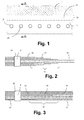
- FIG. 1 shows a plan view of a typical embodiment of a single-row bolt connection with a composite material.
- a region is shown in which a pure fiber composite base laminate 11 is still present without metallic reinforcements.
- a transition region 12 is followed by a transition region 12 and, in turn, a hybrid region 13.
- the reinforcing layers, in particular the metallic layers are already completely present.
- the holes 20 are perpendicular to the plane in FIG. 1 , All holes 20 are provided in the illustrated embodiment in a row behind each other or side by side. It can also be seen a number of bolts 21, which is positioned in the hybrid region 13. The bolts 21 extend through the holes 20.
- FIG. 2 makes a cut through the composite in FIG. 1 along the line AA. It is a first basic version of a local embedding of metal layers.
- FIG. 2 shows a gain by layer addition, that is, between continuous fiber composite layers 31 reinforcing layers 32, in particular reinforcing metal layers are inserted.
- the reinforcing metal layers 32 have an edge 33, in particular so a sheet edge 33.
- This sheet edge 33 can also in the FIG. 1 recognize, it runs, inter alia, in the middle in the transition region 12. At the sheet edge 33 arise in this way deflections of the fiber composite layers 31st
- the reinforcement layers 32 are mostly and also preferably metal layers.
- other materials would also be conceivable which have a reinforcing effect and preferably also possess the further advantageous properties of metals, here for example the homogeneous formation and the uniform structure, which do not assume different values in certain directions.
- the further description is often simplistic of "metal layers" the speech, since it is the preferred embodiment. In principle, however, other reinforcing layers could also be used there.
- FIG. 3 is also a cut through the FIG. 1 in another basic embodiment of local embedding of metal layers or other reinforcement layers 32.
- the local reinforcement is performed by layer replacement, that is, certain layers of the fiber composite layers 31 are replaced by the reinforcing metal sheets or layers 32 , The replaced fiber composite layers 31 are thus interrupted and abut against the reinforcing metal layers 32 at the edge 33 thereof.
- the prior art in both embodiments has a hybrid material in the mechanical joining area, consisting of fiber composite layers 31 and reinforcing metal layers 32, which are homogeneous and undisturbed, except for the bores for receiving the connecting pins 21.
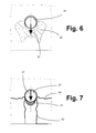
- FIG. 4 and FIG. 5 show the state of stress (from a FEM simulation) of a titanium sheet embedded in a fiber composite laminate as a metal layer 32 around a hole loaded by a titanium bolt 21 (Load direction from left to right).
- the comparison stress of Mises is given considering an elastic / ideal plastic behavior of the titanium of the metal layer 32.
- FIG. 4 shows the state of tension shortly before the beginning of the first plasticity phenomena at the notch bottom.
- the material behavior is elastic.
- the notch base corresponds to the local stress increase at the hole edge of the hole for the bolt 21.
- FIG. 5 shows the state of stress at breakage of the connection, which is accompanied by an accumulation of the plastic deformation (ideally ductile material) in the region of the contact surface with the bolt 21.
- FIG. 2 schematically shows an exemplary influence region 36, which comprises the voltage peaks around a hole in the hybrid laminate 13 loaded in the direction 37 by a bolt 21.
- This area includes the stresses that ultimately lead to failure of the connection.
- FIG. 8 is represented by an embodiment of the subject matter of the present invention.
- a composite material here in plan view.
- reinforcing metal sheets are preferably locally embedded by layer addition (between the fiber composite layers 32) or by layer substitution (in the case of substitution of certain fiber composite layers 32) in the fiber composite laminate.
- bores 20 are provided, which are loaded by a bolt 21.
- the reinforcing layers can be formed, for example, from steel, titanium, cobalt, aluminum or other metals.
- perforations 50 are provided in low-load areas 34 and 35. Highly loaded areas of influence 36 remain homogeneous and undisturbed, so that the maximum strength capacity of the reinforcing metal can be exploited there.
- At least one of the reinforcing layers 32 is as shown in FIG FIG. 8 schematically indicated so a homogeneous and undisturbed area 36 around the bore 20 around. In the regions farther away from the bore 20, where the stress is less, a pattern of perforations 50 and 51 can be seen.
- the shape and the shape of the homogeneous region 36 are derived from the stress state or the fracture characteristic of the special hybrid laminate, which can be determined beforehand.
- the structure of the perforations 50, 51 has different shape sizes of perforations, which in the FIG. 8 only hinted at. Here you can see in particular a different packing density of the perforations.
- the perforation structure may be configured such that a decreasing degree of the number and / or size of the recesses decreases from the low loaded to the highest loaded homogeneous range.
- the decreasing degree of The number and / or size of the recesses can be realized in such a way that the packing density of the perforations 50 decreases, as in detail A of FIG. 8 is shown: the distance of the recesses or perforations 50 and 51 to each other increases from the low-loaded area 34 to the higher-loaded area 35.
- this can also be carried out with variable shape and size of the perforations 50, 51, but with regard to the production of such perforation patterns, the variation of the packing density appears as the more efficient method for a progressive shaping of the recesses.
- the shape of the local homogeneous region, the shape and type of the structured recesses may hereby be different from metal layer 32 to metal layer 32 in the area of a loaded hole for a bolt 21 or for other purposes. In this way, the reinforcement can be tailored for the given case and consequently the maximum efficiency of the reinforcement can be achieved while minimizing the laminate weight.
- FIG. 9 An embodiment for continuous single-row joining of the composite with a series of bolts 21 is shown in FIG. 9 played. It can be seen that the homogeneous regions 36 of the metal layers 32 cover the highest loaded area and are designed in shape and size such that the load introduction and load transfer are optimally ensured.
- the perforations 50 are small compared to the thickness of the metal layer 32.
- the shape of the sheet or the metal layer 32 is still rectangular and flat, so that the integration of the reinforcing sheet continues to be unproblematic is.
- the perforations 50 help to impregnate in the laminate thickness direction, thus simplifying the manufacturing process.
- local hybrid laminates in the conventional design with homogeneous, undisturbed metal sheets or metal layers 32 can only be saturated in the plane direction, since each metal layer 32 represents an injection barrier in the thickness direction.
- the perforations 50, 51 are in any case completely filled with resin from the adjacent fiber composite layers 31 in practice during the production of the composite material with resin. In this way, an additional positive connection between the fiber composite layers 31 and the respective metal layer 32 with the perforations 50, 51 arises. This additionally stabilizes the composite material according to the invention.
Landscapes
- Engineering & Computer Science (AREA)
- Mechanical Engineering (AREA)
- Chemical & Material Sciences (AREA)
- Composite Materials (AREA)
- Laminated Bodies (AREA)
- Manufacture Of Alloys Or Alloy Compounds (AREA)
Applications Claiming Priority (1)
| Application Number | Priority Date | Filing Date | Title |
|---|---|---|---|
| DE102010009769A DE102010009769A1 (de) | 2010-03-01 | 2010-03-01 | Verbundwerkstoff aus mehreren Faserverbundschichten und einem Verstärkungsbereich |
Publications (3)
| Publication Number | Publication Date |
|---|---|
| EP2363282A2 true EP2363282A2 (fr) | 2011-09-07 |
| EP2363282A3 EP2363282A3 (fr) | 2012-08-22 |
| EP2363282B1 EP2363282B1 (fr) | 2019-08-28 |
Family
ID=44260399
Family Applications (1)
| Application Number | Title | Priority Date | Filing Date |
|---|---|---|---|
| EP11156210.4A Active EP2363282B1 (fr) | 2010-03-01 | 2011-02-28 | Matière composite en plusieurs couches composites fibreuses et dotée d'une zone de renforcement |
Country Status (2)
| Country | Link |
|---|---|
| EP (1) | EP2363282B1 (fr) |
| DE (1) | DE102010009769A1 (fr) |
Cited By (2)
| Publication number | Priority date | Publication date | Assignee | Title |
|---|---|---|---|---|
| EP3124221A1 (fr) * | 2015-07-27 | 2017-02-01 | Airbus Operations Limited | Structure composite |
| EP3552813A1 (fr) * | 2018-04-13 | 2019-10-16 | Deutsches Zentrum für Luft- und Raumfahrt e.V. | Composant composite fibreux pourvu de couches intermédiaires et son procédé de fabrication |
Families Citing this family (3)
| Publication number | Priority date | Publication date | Assignee | Title |
|---|---|---|---|---|
| EP3006190B1 (fr) | 2014-10-08 | 2018-12-05 | AIRBUS HELICOPTERS DEUTSCHLAND GmbH | Stratifié composite et composant d'introduction pour un joint d'introduction de charge |
| DE102018110307A1 (de) * | 2018-04-30 | 2019-10-31 | Airbus Defence and Space GmbH | Verbundbauteil und Verfahren zur Herstellung eines Verbundbauteils |
| DE102022115553A1 (de) | 2022-06-22 | 2023-12-28 | Deutsches Zentrum für Luft- und Raumfahrt e.V. | Verfahren zur Herstellung eines Faserverbundbauteils und Faserverbund-Hohlbauteils sowie Windkraftanlage hierzu |
Citations (8)
| Publication number | Priority date | Publication date | Assignee | Title |
|---|---|---|---|---|
| DE7317520U (de) | 1974-03-14 | Lahmann F | Verstärkungselement für die Einleitung von Kräften in geschäumte Kunststoffteile | |
| US4673606A (en) | 1984-02-14 | 1987-06-16 | Harald Unden | Load-introducing armature as component part of a laminated structural element |
| CH681871A5 (en) | 1990-07-13 | 1993-06-15 | Hydrostress Ag | Equipment for producing back cuts with holes of concrete and stone material - uses material removal tools pressed radially outwards during their rotary movement by use of adjustment body moved linearly hydraulically |
| EP1082217B1 (fr) | 1999-03-20 | 2002-06-05 | DLR Deutsches Zentrum für Luft- und Raumfahrt e.V. | Materiau composite comprenant une zone de liaison renforcee |
| DE102006000001A1 (de) | 2005-01-11 | 2006-08-24 | Toyota Jidosha K.K., Toyota | Agentvorrichtung für ein Fahrzeug, Agentsystem, Agentsteuerverfahren, Endgerätvorrichtung und Informationsbereitstellungsverfahren |
| US7115323B2 (en) | 2003-08-28 | 2006-10-03 | The Boeing Company | Titanium foil ply replacement in layup of composite skin |
| DE102006000144A1 (de) | 2005-03-30 | 2006-10-05 | Toyota Jidosha K.K., Toyota | Fehldiagnosevorrichtung für ein Fahrzeug und Fehldiagnoseverfahren für ein Fahrzeug |
| DE102006001444A1 (de) | 2006-01-10 | 2007-07-12 | Deutsches Zentrum für Luft- und Raumfahrt e.V. | Verbundwerkstoff |
Family Cites Families (5)
| Publication number | Priority date | Publication date | Assignee | Title |
|---|---|---|---|---|
| FI83791C (fi) * | 1989-08-24 | 1991-08-26 | Neste Oy | Slitstarkt band och foerfarande foer framstaellning av detta. |
| JPH0661899B2 (ja) * | 1991-02-22 | 1994-08-17 | 新日鐵化学株式会社 | 複合パネルの製造方法 |
| JPH06198806A (ja) * | 1992-12-28 | 1994-07-19 | Tonen Corp | プリプレグ |
| DE19925588A1 (de) * | 1999-06-04 | 2000-12-07 | Deutsch Zentr Luft & Raumfahrt | Faden zur Verbindung von Fasern eines Faserhalbzeuges sowie Faserhalbzeug, und Verfahren zur Herstellung von Faserverbundwerkstoffen |
| JP5625260B2 (ja) * | 2009-04-21 | 2014-11-19 | 株式会社豊田自動織機 | 繊維強化複合材及び繊維強化複合材の締結構造 |
-
2010
- 2010-03-01 DE DE102010009769A patent/DE102010009769A1/de not_active Withdrawn
-
2011
- 2011-02-28 EP EP11156210.4A patent/EP2363282B1/fr active Active
Patent Citations (8)
| Publication number | Priority date | Publication date | Assignee | Title |
|---|---|---|---|---|
| DE7317520U (de) | 1974-03-14 | Lahmann F | Verstärkungselement für die Einleitung von Kräften in geschäumte Kunststoffteile | |
| US4673606A (en) | 1984-02-14 | 1987-06-16 | Harald Unden | Load-introducing armature as component part of a laminated structural element |
| CH681871A5 (en) | 1990-07-13 | 1993-06-15 | Hydrostress Ag | Equipment for producing back cuts with holes of concrete and stone material - uses material removal tools pressed radially outwards during their rotary movement by use of adjustment body moved linearly hydraulically |
| EP1082217B1 (fr) | 1999-03-20 | 2002-06-05 | DLR Deutsches Zentrum für Luft- und Raumfahrt e.V. | Materiau composite comprenant une zone de liaison renforcee |
| US7115323B2 (en) | 2003-08-28 | 2006-10-03 | The Boeing Company | Titanium foil ply replacement in layup of composite skin |
| DE102006000001A1 (de) | 2005-01-11 | 2006-08-24 | Toyota Jidosha K.K., Toyota | Agentvorrichtung für ein Fahrzeug, Agentsystem, Agentsteuerverfahren, Endgerätvorrichtung und Informationsbereitstellungsverfahren |
| DE102006000144A1 (de) | 2005-03-30 | 2006-10-05 | Toyota Jidosha K.K., Toyota | Fehldiagnosevorrichtung für ein Fahrzeug und Fehldiagnoseverfahren für ein Fahrzeug |
| DE102006001444A1 (de) | 2006-01-10 | 2007-07-12 | Deutsches Zentrum für Luft- und Raumfahrt e.V. | Verbundwerkstoff |
Cited By (2)
| Publication number | Priority date | Publication date | Assignee | Title |
|---|---|---|---|---|
| EP3124221A1 (fr) * | 2015-07-27 | 2017-02-01 | Airbus Operations Limited | Structure composite |
| EP3552813A1 (fr) * | 2018-04-13 | 2019-10-16 | Deutsches Zentrum für Luft- und Raumfahrt e.V. | Composant composite fibreux pourvu de couches intermédiaires et son procédé de fabrication |
Also Published As
| Publication number | Publication date |
|---|---|
| DE102010009769A1 (de) | 2011-09-01 |
| EP2363282B1 (fr) | 2019-08-28 |
| EP2363282A3 (fr) | 2012-08-22 |
Similar Documents
| Publication | Publication Date | Title |
|---|---|---|
| DE10301445B4 (de) | Leichtbau-Strukturbauteil insbesondere für Flugzeuge und Verfahren zu seiner Herstellung | |
| EP2363282B1 (fr) | Matière composite en plusieurs couches composites fibreuses et dotée d'une zone de renforcement | |
| DE102010006144B4 (de) | Verkleidung für eine Flugzeugstruktur | |
| EP3953602B1 (fr) | Élément de ressort à flexion ayant un material renforcé de fibres | |
| EP1312467A1 (fr) | Matériau composite renforcé par des fibres métalliques et procédé de fabrication | |
| EP1735211B1 (fr) | Revetement pour structure d'avion | |
| EP1678390A1 (fr) | Composant comportant une structure auxetique | |
| DE102008024585B4 (de) | Federelement für eine Feder-Dämpfer-Anordnung | |
| DE102015102064A1 (de) | Blattfeder aus einem Faserkunststoffverbundmaterial | |
| DE102015014489A1 (de) | Werkstück aus teilgehärtetem Stahlblech | |
| DE102008052604B4 (de) | Faserverstärkter Verbundwerkstoff sowie Verfahren zur Herstellung desselben | |
| EP3498460A1 (fr) | Agencement de composant composite renforcé par des fibres, système de composant composite renforcé par des fibres et procédé de fabrication d'un système de composant composite renforcé par des fibres | |
| DE102010035324A1 (de) | Strukturelement aus einem Hybridlaminat | |
| EP1666354A1 (fr) | Composant structurel, procédé de fabrication d'un composant structurel et utilisation d'un composant structurel dans le revêtement d'un aéronef | |
| WO2014108240A1 (fr) | Procédé de fabrication d'un composant structurel d'un véhicule | |
| WO2006119732A1 (fr) | Composant structurel metallique monobloc ayant une resistance remanente amelioree | |
| EP3788210B1 (fr) | Système d'ancrage à force transversale | |
| DE102007016634A1 (de) | Fügeelement, Verbundstruktur und Verfahren zur Herstellung einer Verbundstruktur | |
| EP4512972B1 (fr) | Elément de plafond en béton avec âme en béton | |
| EP3242983A1 (fr) | Element de coffrage de panneau de cadre | |
| DE102014202566A1 (de) | Verbundteil umfassend eine Metallkomponente und eine endlosfasernverstärkte Kunststoffmaterialkomponente | |
| DE102018105246B4 (de) | Verfahren zur Herstellung eines verstärkten Faserverbundwerkstoffs, Faserverbundwerkstoff und Luft- oder Raumfahrzeug | |
| DE102008049257A1 (de) | Pleuelstange | |
| DE202024002688U1 (de) | Beton-Deckenelement mit Betonsteg | |
| DE102021128827A1 (de) | Fahrtreppenvorrichtung mit freitragender fachwerkartiger Abstützstruktur mit Zugstreben aus Hybridmaterial sowie Verfahren und Verwendung |
Legal Events
| Date | Code | Title | Description |
|---|---|---|---|
| PUAI | Public reference made under article 153(3) epc to a published international application that has entered the european phase |
Free format text: ORIGINAL CODE: 0009012 |
|
| AK | Designated contracting states |
Kind code of ref document: A2 Designated state(s): AL AT BE BG CH CY CZ DE DK EE ES FI FR GB GR HR HU IE IS IT LI LT LU LV MC MK MT NL NO PL PT RO RS SE SI SK SM TR |
|
| AX | Request for extension of the european patent |
Extension state: BA ME |
|
| PUAL | Search report despatched |
Free format text: ORIGINAL CODE: 0009013 |
|
| AK | Designated contracting states |
Kind code of ref document: A3 Designated state(s): AL AT BE BG CH CY CZ DE DK EE ES FI FR GB GR HR HU IE IS IT LI LT LU LV MC MK MT NL NO PL PT RO RS SE SI SK SM TR |
|
| AX | Request for extension of the european patent |
Extension state: BA ME |
|
| RIC1 | Information provided on ipc code assigned before grant |
Ipc: B32B 5/24 20060101ALI20120713BHEP Ipc: B32B 15/14 20060101ALI20120713BHEP Ipc: B32B 3/02 20060101ALI20120713BHEP Ipc: B32B 3/10 20060101AFI20120713BHEP Ipc: B32B 7/04 20060101ALI20120713BHEP Ipc: B29C 70/00 20060101ALI20120713BHEP Ipc: B32B 7/08 20060101ALI20120713BHEP Ipc: B32B 7/02 20060101ALI20120713BHEP Ipc: B32B 3/26 20060101ALI20120713BHEP Ipc: B32B 5/26 20060101ALI20120713BHEP Ipc: B32B 15/00 20060101ALI20120713BHEP |
|
| 17P | Request for examination filed |
Effective date: 20130221 |
|
| STAA | Information on the status of an ep patent application or granted ep patent |
Free format text: STATUS: EXAMINATION IS IN PROGRESS |
|
| 17Q | First examination report despatched |
Effective date: 20170914 |
|
| GRAP | Despatch of communication of intention to grant a patent |
Free format text: ORIGINAL CODE: EPIDOSNIGR1 |
|
| STAA | Information on the status of an ep patent application or granted ep patent |
Free format text: STATUS: GRANT OF PATENT IS INTENDED |
|
| INTG | Intention to grant announced |
Effective date: 20190507 |
|
| GRAS | Grant fee paid |
Free format text: ORIGINAL CODE: EPIDOSNIGR3 |
|
| GRAA | (expected) grant |
Free format text: ORIGINAL CODE: 0009210 |
|
| STAA | Information on the status of an ep patent application or granted ep patent |
Free format text: STATUS: THE PATENT HAS BEEN GRANTED |
|
| AK | Designated contracting states |
Kind code of ref document: B1 Designated state(s): AL AT BE BG CH CY CZ DE DK EE ES FI FR GB GR HR HU IE IS IT LI LT LU LV MC MK MT NL NO PL PT RO RS SE SI SK SM TR |
|
| REG | Reference to a national code |
Ref country code: GB Ref legal event code: FG4D Free format text: NOT ENGLISH |
|
| REG | Reference to a national code |
Ref country code: CH Ref legal event code: EP |
|
| REG | Reference to a national code |
Ref country code: AT Ref legal event code: REF Ref document number: 1171894 Country of ref document: AT Kind code of ref document: T Effective date: 20190915 |
|
| REG | Reference to a national code |
Ref country code: IE Ref legal event code: FG4D Free format text: LANGUAGE OF EP DOCUMENT: GERMAN |
|
| REG | Reference to a national code |
Ref country code: DE Ref legal event code: R096 Ref document number: 502011016038 Country of ref document: DE |
|
| REG | Reference to a national code |
Ref country code: NL Ref legal event code: MP Effective date: 20190828 |
|
| REG | Reference to a national code |
Ref country code: LT Ref legal event code: MG4D |
|
| PG25 | Lapsed in a contracting state [announced via postgrant information from national office to epo] |
Ref country code: FI Free format text: LAPSE BECAUSE OF FAILURE TO SUBMIT A TRANSLATION OF THE DESCRIPTION OR TO PAY THE FEE WITHIN THE PRESCRIBED TIME-LIMIT Effective date: 20190828 Ref country code: NO Free format text: LAPSE BECAUSE OF FAILURE TO SUBMIT A TRANSLATION OF THE DESCRIPTION OR TO PAY THE FEE WITHIN THE PRESCRIBED TIME-LIMIT Effective date: 20191128 Ref country code: PT Free format text: LAPSE BECAUSE OF FAILURE TO SUBMIT A TRANSLATION OF THE DESCRIPTION OR TO PAY THE FEE WITHIN THE PRESCRIBED TIME-LIMIT Effective date: 20191230 Ref country code: HR Free format text: LAPSE BECAUSE OF FAILURE TO SUBMIT A TRANSLATION OF THE DESCRIPTION OR TO PAY THE FEE WITHIN THE PRESCRIBED TIME-LIMIT Effective date: 20190828 Ref country code: LT Free format text: LAPSE BECAUSE OF FAILURE TO SUBMIT A TRANSLATION OF THE DESCRIPTION OR TO PAY THE FEE WITHIN THE PRESCRIBED TIME-LIMIT Effective date: 20190828 Ref country code: NL Free format text: LAPSE BECAUSE OF FAILURE TO SUBMIT A TRANSLATION OF THE DESCRIPTION OR TO PAY THE FEE WITHIN THE PRESCRIBED TIME-LIMIT Effective date: 20190828 Ref country code: BG Free format text: LAPSE BECAUSE OF FAILURE TO SUBMIT A TRANSLATION OF THE DESCRIPTION OR TO PAY THE FEE WITHIN THE PRESCRIBED TIME-LIMIT Effective date: 20191128 Ref country code: SE Free format text: LAPSE BECAUSE OF FAILURE TO SUBMIT A TRANSLATION OF THE DESCRIPTION OR TO PAY THE FEE WITHIN THE PRESCRIBED TIME-LIMIT Effective date: 20190828 |
|
| PG25 | Lapsed in a contracting state [announced via postgrant information from national office to epo] |
Ref country code: GR Free format text: LAPSE BECAUSE OF FAILURE TO SUBMIT A TRANSLATION OF THE DESCRIPTION OR TO PAY THE FEE WITHIN THE PRESCRIBED TIME-LIMIT Effective date: 20191129 Ref country code: LV Free format text: LAPSE BECAUSE OF FAILURE TO SUBMIT A TRANSLATION OF THE DESCRIPTION OR TO PAY THE FEE WITHIN THE PRESCRIBED TIME-LIMIT Effective date: 20190828 Ref country code: AL Free format text: LAPSE BECAUSE OF FAILURE TO SUBMIT A TRANSLATION OF THE DESCRIPTION OR TO PAY THE FEE WITHIN THE PRESCRIBED TIME-LIMIT Effective date: 20190828 Ref country code: RS Free format text: LAPSE BECAUSE OF FAILURE TO SUBMIT A TRANSLATION OF THE DESCRIPTION OR TO PAY THE FEE WITHIN THE PRESCRIBED TIME-LIMIT Effective date: 20190828 Ref country code: IS Free format text: LAPSE BECAUSE OF FAILURE TO SUBMIT A TRANSLATION OF THE DESCRIPTION OR TO PAY THE FEE WITHIN THE PRESCRIBED TIME-LIMIT Effective date: 20191228 Ref country code: ES Free format text: LAPSE BECAUSE OF FAILURE TO SUBMIT A TRANSLATION OF THE DESCRIPTION OR TO PAY THE FEE WITHIN THE PRESCRIBED TIME-LIMIT Effective date: 20190828 |
|
| PG25 | Lapsed in a contracting state [announced via postgrant information from national office to epo] |
Ref country code: TR Free format text: LAPSE BECAUSE OF FAILURE TO SUBMIT A TRANSLATION OF THE DESCRIPTION OR TO PAY THE FEE WITHIN THE PRESCRIBED TIME-LIMIT Effective date: 20190828 |
|
| PG25 | Lapsed in a contracting state [announced via postgrant information from national office to epo] |
Ref country code: RO Free format text: LAPSE BECAUSE OF FAILURE TO SUBMIT A TRANSLATION OF THE DESCRIPTION OR TO PAY THE FEE WITHIN THE PRESCRIBED TIME-LIMIT Effective date: 20190828 Ref country code: IT Free format text: LAPSE BECAUSE OF FAILURE TO SUBMIT A TRANSLATION OF THE DESCRIPTION OR TO PAY THE FEE WITHIN THE PRESCRIBED TIME-LIMIT Effective date: 20190828 Ref country code: PL Free format text: LAPSE BECAUSE OF FAILURE TO SUBMIT A TRANSLATION OF THE DESCRIPTION OR TO PAY THE FEE WITHIN THE PRESCRIBED TIME-LIMIT Effective date: 20190828 Ref country code: DK Free format text: LAPSE BECAUSE OF FAILURE TO SUBMIT A TRANSLATION OF THE DESCRIPTION OR TO PAY THE FEE WITHIN THE PRESCRIBED TIME-LIMIT Effective date: 20190828 Ref country code: EE Free format text: LAPSE BECAUSE OF FAILURE TO SUBMIT A TRANSLATION OF THE DESCRIPTION OR TO PAY THE FEE WITHIN THE PRESCRIBED TIME-LIMIT Effective date: 20190828 |
|
| PG25 | Lapsed in a contracting state [announced via postgrant information from national office to epo] |
Ref country code: CZ Free format text: LAPSE BECAUSE OF FAILURE TO SUBMIT A TRANSLATION OF THE DESCRIPTION OR TO PAY THE FEE WITHIN THE PRESCRIBED TIME-LIMIT Effective date: 20190828 Ref country code: SM Free format text: LAPSE BECAUSE OF FAILURE TO SUBMIT A TRANSLATION OF THE DESCRIPTION OR TO PAY THE FEE WITHIN THE PRESCRIBED TIME-LIMIT Effective date: 20190828 Ref country code: SK Free format text: LAPSE BECAUSE OF FAILURE TO SUBMIT A TRANSLATION OF THE DESCRIPTION OR TO PAY THE FEE WITHIN THE PRESCRIBED TIME-LIMIT Effective date: 20190828 Ref country code: IS Free format text: LAPSE BECAUSE OF FAILURE TO SUBMIT A TRANSLATION OF THE DESCRIPTION OR TO PAY THE FEE WITHIN THE PRESCRIBED TIME-LIMIT Effective date: 20200224 |
|
| REG | Reference to a national code |
Ref country code: DE Ref legal event code: R097 Ref document number: 502011016038 Country of ref document: DE |
|
| PLBE | No opposition filed within time limit |
Free format text: ORIGINAL CODE: 0009261 |
|
| STAA | Information on the status of an ep patent application or granted ep patent |
Free format text: STATUS: NO OPPOSITION FILED WITHIN TIME LIMIT |
|
| PG2D | Information on lapse in contracting state deleted |
Ref country code: IS |
|
| 26N | No opposition filed |
Effective date: 20200603 |
|
| PG25 | Lapsed in a contracting state [announced via postgrant information from national office to epo] |
Ref country code: SI Free format text: LAPSE BECAUSE OF FAILURE TO SUBMIT A TRANSLATION OF THE DESCRIPTION OR TO PAY THE FEE WITHIN THE PRESCRIBED TIME-LIMIT Effective date: 20190828 |
|
| REG | Reference to a national code |
Ref country code: CH Ref legal event code: PL |
|
| GBPC | Gb: european patent ceased through non-payment of renewal fee |
Effective date: 20200228 |
|
| REG | Reference to a national code |
Ref country code: BE Ref legal event code: MM Effective date: 20200229 |
|
| PG25 | Lapsed in a contracting state [announced via postgrant information from national office to epo] |
Ref country code: MC Free format text: LAPSE BECAUSE OF FAILURE TO SUBMIT A TRANSLATION OF THE DESCRIPTION OR TO PAY THE FEE WITHIN THE PRESCRIBED TIME-LIMIT Effective date: 20190828 Ref country code: LU Free format text: LAPSE BECAUSE OF NON-PAYMENT OF DUE FEES Effective date: 20200228 |
|
| PG25 | Lapsed in a contracting state [announced via postgrant information from national office to epo] |
Ref country code: CH Free format text: LAPSE BECAUSE OF NON-PAYMENT OF DUE FEES Effective date: 20200229 Ref country code: LI Free format text: LAPSE BECAUSE OF NON-PAYMENT OF DUE FEES Effective date: 20200229 |
|
| PG25 | Lapsed in a contracting state [announced via postgrant information from national office to epo] |
Ref country code: FR Free format text: LAPSE BECAUSE OF NON-PAYMENT OF DUE FEES Effective date: 20200229 Ref country code: GB Free format text: LAPSE BECAUSE OF NON-PAYMENT OF DUE FEES Effective date: 20200228 Ref country code: IE Free format text: LAPSE BECAUSE OF NON-PAYMENT OF DUE FEES Effective date: 20200228 |
|
| PG25 | Lapsed in a contracting state [announced via postgrant information from national office to epo] |
Ref country code: BE Free format text: LAPSE BECAUSE OF NON-PAYMENT OF DUE FEES Effective date: 20200229 |
|
| REG | Reference to a national code |
Ref country code: AT Ref legal event code: MM01 Ref document number: 1171894 Country of ref document: AT Kind code of ref document: T Effective date: 20200228 |
|
| PG25 | Lapsed in a contracting state [announced via postgrant information from national office to epo] |
Ref country code: AT Free format text: LAPSE BECAUSE OF NON-PAYMENT OF DUE FEES Effective date: 20200228 |
|
| PGFP | Annual fee paid to national office [announced via postgrant information from national office to epo] |
Ref country code: DE Payment date: 20210113 Year of fee payment: 11 |
|
| PG25 | Lapsed in a contracting state [announced via postgrant information from national office to epo] |
Ref country code: MT Free format text: LAPSE BECAUSE OF FAILURE TO SUBMIT A TRANSLATION OF THE DESCRIPTION OR TO PAY THE FEE WITHIN THE PRESCRIBED TIME-LIMIT Effective date: 20190828 Ref country code: CY Free format text: LAPSE BECAUSE OF FAILURE TO SUBMIT A TRANSLATION OF THE DESCRIPTION OR TO PAY THE FEE WITHIN THE PRESCRIBED TIME-LIMIT Effective date: 20190828 |
|
| PG25 | Lapsed in a contracting state [announced via postgrant information from national office to epo] |
Ref country code: MK Free format text: LAPSE BECAUSE OF FAILURE TO SUBMIT A TRANSLATION OF THE DESCRIPTION OR TO PAY THE FEE WITHIN THE PRESCRIBED TIME-LIMIT Effective date: 20190828 |
|
| REG | Reference to a national code |
Ref country code: DE Ref legal event code: R119 Ref document number: 502011016038 Country of ref document: DE |
|
| PG25 | Lapsed in a contracting state [announced via postgrant information from national office to epo] |
Ref country code: DE Free format text: LAPSE BECAUSE OF NON-PAYMENT OF DUE FEES Effective date: 20220901 |