EP3788210B1 - Système d'ancrage à force transversale - Google Patents
Système d'ancrage à force transversale Download PDFInfo
- Publication number
- EP3788210B1 EP3788210B1 EP18724500.6A EP18724500A EP3788210B1 EP 3788210 B1 EP3788210 B1 EP 3788210B1 EP 18724500 A EP18724500 A EP 18724500A EP 3788210 B1 EP3788210 B1 EP 3788210B1
- Authority
- EP
- European Patent Office
- Prior art keywords
- load introduction
- section
- component
- shear force
- transmitted
- Prior art date
- Legal status (The legal status is an assumption and is not a legal conclusion. Google has not performed a legal analysis and makes no representation as to the accuracy of the status listed.)
- Active
Links
Images






Classifications
-
- E—FIXED CONSTRUCTIONS
- E04—BUILDING
- E04B—GENERAL BUILDING CONSTRUCTIONS; WALLS, e.g. PARTITIONS; ROOFS; FLOORS; CEILINGS; INSULATION OR OTHER PROTECTION OF BUILDINGS
- E04B1/00—Constructions in general; Structures which are not restricted either to walls, e.g. partitions, or floors or ceilings or roofs
- E04B1/38—Connections for building structures in general
- E04B1/41—Connecting devices specially adapted for embedding in concrete or masonry
- E04B1/4114—Elements with sockets
- E04B1/4121—Elements with sockets with internal threads or non-adjustable captive nuts
-
- E—FIXED CONSTRUCTIONS
- E04—BUILDING
- E04B—GENERAL BUILDING CONSTRUCTIONS; WALLS, e.g. PARTITIONS; ROOFS; FLOORS; CEILINGS; INSULATION OR OTHER PROTECTION OF BUILDINGS
- E04B1/00—Constructions in general; Structures which are not restricted either to walls, e.g. partitions, or floors or ceilings or roofs
- E04B1/38—Connections for building structures in general
- E04B1/41—Connecting devices specially adapted for embedding in concrete or masonry
-
- E—FIXED CONSTRUCTIONS
- E04—BUILDING
- E04B—GENERAL BUILDING CONSTRUCTIONS; WALLS, e.g. PARTITIONS; ROOFS; FLOORS; CEILINGS; INSULATION OR OTHER PROTECTION OF BUILDINGS
- E04B1/00—Constructions in general; Structures which are not restricted either to walls, e.g. partitions, or floors or ceilings or roofs
- E04B1/38—Connections for building structures in general
- E04B1/48—Dowels, i.e. members adapted to penetrate the surfaces of two parts and to take the shear stresses
- E04B1/483—Shear dowels to be embedded in concrete
Definitions
- the present invention relates to a shear force anchor as a connecting means for transmitting higher shear forces within components, transverse to the component direction, a connecting structure consisting of such a shear force anchor and the component, and a method for ensuring a transmission of a force in a specific direction between any two bodies through a defined section.
- Fastening systems for introducing loads into the concrete are known from concrete construction and are usually made of metal or plastic. While dowels are mainly used for subsequent fastening systems that are installed after the concrete has been poured, so-called inserts are dowel-shaped fastening systems or anchor rails with head bolts and other more complex shapes. The term “insert” comes from the manufacturing process, as they are inserted and attached to the formwork before the concrete is poured.
- EP 2 743 415 A1 an expansion joint construction element, whereby double-headed bolts are attached to the side walls of a heavy-duty mandrel and a bearing sleeve, each of which is aligned vertically in the installation position.
- EP 2 907 932 A1 discloses an anchor channel in which a sub-anchor is provided to increase the resistance to shear forces.
- EP 1 477 620 A1 shows a fastening element for embedding with an end section in a concrete component and for absorbing transverse forces, wherein partial surfaces are present on the end section which can be aligned in the direction of the transverse forces to be absorbed, which partial surfaces comprise a front partial surface and a rear partial surface arranged offset relative to this direction, and the rear partial surface is provided with padding.
- Load-bearing devices in the form of anchors for precast concrete elements are still to be tested, for example, on the basis of the Fig.1 of the document EP 0 122 521 B1 known from the state of the art.
- anchors are cast into precast concrete elements and subjected to tensile and shear forces in the component.
- the anchor calculations are dimensioned and integrated accordingly to transfer the loads.
- These anchors are typically installed in the middle of the component thickness, as this is where the anchors are most sensibly positioned for each load.
- the anchors are provided with bolts or, for example, carry corrugated steel anchors. The resulting undercuts anchor these anchors in the concrete and secure them against tearing out under tensile load.
- the present invention was made with the above-mentioned problem in mind.
- the object is therefore to create a connecting means for transmitting higher transverse forces, which enables the use of components in a slim design.
- the fracture cone therefore also increases in size, which means it has to overcome a greater resistance, which increases the failure load.
- a shear force anchor for transmitting shear forces transversely to the longitudinal direction of a component within components primarily made of concrete is provided as a connecting means, which has the following: a connection section for introducing at least one shear force into the shear force anchor, which is connected to at least one load introduction section that can be contacted with the component in order to transmit at least one force component in the direction of the shear force to be transmitted into the component, characterized in that the connection section is spaced from the load introduction section in the direction of the shear force to be transmitted.
- At least one shear force can be introduced into the shear force anchor via the connection section.
- the shear force can be transmitted via the load introduction section not only directly into the component at the connection section, but also at least partially at the load introduction section, whereby the load introduction section is in direct contact with the component and transmits at least one component in the direction of the shear force to be transmitted. Since the connection section is spaced from the load introduction section in the direction of the shear force to be transmitted, the load introduction section is conversely spaced from the connection section in a direction opposite to the direction of the shear force to be transmitted.
- the shear force anchor has two load introduction sections for transmitting opposing shear forces, wherein the first load introduction section can transmit a force component in one direction of the shear forces to be transmitted into the component, and the second load introduction section can transmit a force component in the other direction of the shear forces to be transmitted into the component and is spaced from the first load introduction section in one direction of the shear forces to be transmitted, and wherein the connection section is connected to both load introduction sections.
- Such a shear force anchor is ideal for transmitting opposing or alternating shear forces, with one load introduction section transmitting the shear force in one direction at least component by component and the other transmitting the shear force in the other direction at least component by component. Since the two load introduction sections are connected to one another, the opposing shear forces can be introduced into the shear force anchor via a connection section and transferred from the respective load introduction section into the component. Because the second load introduction section is spaced from the first load introduction section in one direction of the shear forces to be transmitted, a large component thickness is available for the transmission of the respective force component in the direction of the respective shear force to be transmitted through the respective load introduction section.
- the shear force anchor additionally has at least one load introduction prevention section, which partially, but preferably completely, prevents a force transmission with a component in the direction of the shear force to be transmitted by the respective load introduction section into the component.
- a load introduction prevention section which is designed in such a way that it transfers almost no force component to the component in the direction of the respective transverse force to be transferred, the transverse force can mostly only be transferred to the component at the defined section of the load introduction section.
- the load introduction prevention section therefore causes the force component transferred to the respective load introduction section to be increased in the direction of the respective transverse force to be transferred. A large force component is thus transferred to the component in the direction of the respective transverse force to be transferred over a large component thickness.
- the load introduction prevention section is provided in sections on the respective load introduction section and is provided at least in sections on the connection section. This prevents a large force component from being transmitted in the direction of the respective transverse force to be transmitted into the component through the connection section and the transmission of the transverse force through the respective load introduction section takes place in a defined area of the respective load introduction section.
- the load introduction prevention section can be provided at a distance from the respective load introduction section in the direction of the transverse force to be transmitted.
- the load introduction prevention section is provided at a distance from the respective load introduction section in the direction of the transverse force to be transmitted, it can be reliably ensured that a large component thickness is used to transmit the respective transverse force into the component. Since the load introduction prevention section is provided in front of the respective load introduction section in the direction of the transverse force, according to the installation position described above, a smaller part of the component thickness is available from the load introduction prevention section in the direction of the transverse force to be transmitted than from the respective load introduction section. Since the transverse force is largely transmitted to the component via the load introduction section, a large part of the component thickness is used to transmit the transverse force.
- a further aspect of the invention provides that the force component to be transmitted from the respective load introduction section into the component in the direction of the respective transverse force to be transmitted can be greater than the force component to be transmitted from the load introduction prevention section into the component in the direction of the respective transverse force to be transmitted.
- the load introduction prevention section may be able to transfer a force component in the direction of the transverse force, but this is always smaller than the force component in the direction of the transverse force that is transferred to the component through the load introduction section.
- a further aspect of the invention provides that the respective load introduction section can have at least one load introduction surface which can be contacted with the component and whose pointing surface normal has a component in the direction of the respective transverse force to be transmitted.
- the load introduction surface with a pointing surface normal which is the normal of the load introduction surface that points away from the respective load introduction surface of the respective load introduction section, which has a component in the direction of the respective transverse force to be transferred, causes a compressive stress in the component. This allows the failure mode to be brought about in a targeted manner by a breakout cone, which arises when compressive stress is applied transversely to the longitudinal direction of the component.
- the multiple load introduction surfaces of the respective load introduction section can be arranged in one plane.
- the load introduction surfaces of the respective load introduction section are preferably perpendicular to the direction of the transverse force to be transmitted.
- the shear force anchor With load introduction surfaces lying in one plane, the shear force anchor can be manufactured easily. Furthermore, a more even load on the component is achieved. If the load introduction surfaces of the respective load introduction section are perpendicular to the direction of the shear force to be transferred, the shear force vector and the surface normal vector of the load introduction surface run parallel, which promotes the formation of a fracture cone. The component is subjected to purely compressive stress transversely to the longitudinal direction of the component by the component of the shear force transferred by the load introduction surfaces of the respective load introduction section. This means that no shearing occurs at the boundary between the load introduction surface and the component.
- the load introduction prevention section can be provided at least in sections on all surfaces that lie from the load introduction surfaces of the respective load introduction section in the direction of the respective transverse force to be transmitted and whose leading surface normals have a component in the direction of the respective transverse force to be transmitted.
- the load introduction prevention section is provided on all surfaces except the load introduction surfaces of the respective load introduction section.
- a shear force anchor with a large-area load introduction prevention section can further reduce sound transmission or vibration.
- a further aspect of the invention provides that a web can extend from the connection section to both sides, which establishes the connection to the respective load introduction section.
- connection section Since the connection section is provided between the two load introduction areas, no additional installation space for the connection section needs to be provided in the component.
- the transverse force to be transmitted is guided via the webs to the respective load introduction section, whereby the web represents a structurally simple form of connection between the connection section and the load introduction sections.
- the connecting section is a sleeve.
- the sleeve allows for easy attachment of connecting elements for introducing forces into the shear anchor.
- connecting elements can be screwed into the sleeve using a thread. If the axis of the sleeve preferably runs in the longitudinal direction of the component perpendicular to the shear forces to be transmitted, a bolt for introducing loads into the shear anchor and an anchor bolt for anchoring tensile forces in the component can be attached to the sleeve.
- the load introduction bolt can also easily introduce tensile and compressive forces in the longitudinal direction of the component into the shear anchor.
- the load introduction bolt can be attached to the sleeve from one direction, whereby the anchor bolt can be attached to the sleeve from the opposite direction.
- the anchor bolt prevents tearing out in the longitudinal direction of the component when tensile loads are applied in the longitudinal direction of the component.
- the load introduction prevention section can consist of a compressible elastic material, preferably of closed-cell foam.
- the load introduction prevention section can deform elastically in the direction of the shear force under the acting shear force and this elastic deformation creates a spring effect, due to which the shear force is only transferred to the component to a very small extent.
- a compressible material also allows deformations under compressive stress on the load introduction prevention section if the load introduction prevention section is surrounded by concrete on all sides and transverse expansions are thus prevented.
- connection section, the webs and the respective load introduction sections can consist of a stiffer material than that of the load introduction prevention section, preferably of galvanized steel.
- connection structure consisting of a component and a shear anchor according to the invention, wherein the load introduction prevention section can be provided at least partially as a gap between the component and the shear anchor.
- an elastic material can be partially or completely dispensed with, saving weight and material. If there is a gap, no component in the direction of the shear force is transferred to the component in the area of the gap.
- a support structure such as a core must be provided during the concrete pouring process to keep the concrete at a distance. This support structure can then be removed after the casting, for example by etching.
- the shear force anchor can be provided with a dissolving material to form a gap, which dissolves after the concrete is poured.
- the present disclosure relates to a method for ensuring a transmission of a force in a specific direction between any two bodies through a defined load introduction section, wherein one body has the defined load introduction section, via which it is in contact with the other body and the load introduction section can transmit a force component in the direction of the force in the specific direction to the other body, and in the one body, all sections with the exception of the load introduction section, which can transmit a force component in the direction of the force in the specific direction to the other body, are provided with a layer covering these sections, which is easily deformable compared to the load introduction section and via this deformable layer is in contact with the other body, whereby when one body is loaded by the force in the specific direction, the deformable layer deforms and the force in the specific direction is transferred to the other body with a smaller component than through the load introduction section.
- This method describes the above-mentioned principle, according to which, if a force can be transmitted in one direction to several sections in a component, the majority of the force is transmitted to the connection with the greatest rigidity. Because the deformable layer can be deformed more easily than the load introduction section, or more precisely than the connection of the load introduction section to the other body, a large part of the force is transmitted in the specific direction through the load introduction section to the other body.
- the shear force anchor according to the invention is based on this principle, which is described in more detail in the following drawings.
- a breakout cone is formed as in Fig. 11 shown.
- the safety concept against this concrete edge fracture provides that the anchor has a sufficient edge distance to the final component edge.
- These edge distances to be maintained are dominated by the transverse forces, which means that they usually determine the component thickness to a large extent, whereby the failure load can be increased as the component thickness increases and the absorbable transverse force can be increased.
- components with a large component thickness are therefore often provided, especially in the case of alternating or opposing transverse forces.
- the Fig. 1a shows a perspective view of the shear force anchor 1 according to the invention in a first embodiment for transmitting higher shear forces primarily for components 10 with low component thicknesses.
- Fig. 1b shows the shear force anchor 1 in a sectional view, the section being drawn from the dash-dot line along the arrows A.
- the shear force anchor 1 according to the invention has a connection section 2 through which forces can be introduced into the shear force anchor. At least one shear force should be able to be introduced into the shear force anchor 1 through the connection section.
- the shear force anchor 1 has load introduction sections 51 and 52 on both sides of the connection section 2 for transmitting alternating or opposing shear forces into the component 10, namely a first right cuboid load introduction section 51 for transmitting a force component in one direction of the opposing shear forces to be transmitted into the component 10 and a second left cuboid load introduction section 52 for transmitting a force component in the other direction of the shear forces to be transmitted in the component 10.
- the load introduction sections 51 and 52 are connected to the connection section via webs 41 and 42, which extend on both sides of the connection section 2.
- Each of the two load introduction sections 51 and 52 has a first rectangular load introduction surface 61 and a second rectangular load introduction surface 62.
- the load introduction sections 51 and 52 are formed not only by the load introduction surfaces 61 and 62 but also by the surfaces created when the load introduction surfaces 61 and 62 are created. As in Fig. 1a and 1b In the case of the cuboid load introduction sections 51 and 52, these are the rear surface 63 of the load introduction surfaces 61 and 62, the two side surfaces 64, which in Fig. 1a upper surface 65 and the Fig. 1a lower surface 66. This results in a dumbbell-shaped appearance of the shear force anchor 1.
- a load introduction prevention section 3 is provided over a large area on the shear force anchor 1, but not on the load introduction surfaces 61 and 62 and the upper surface 65 of the load introduction sections 51 and 52 and the adjoining upper surface of the webs.
- the load introduction prevention section 3 is provided on the rear side 63 of the respective load introduction surfaces 61 and 62, i.e. on a surface on the opposite side of the load introduction surfaces 61 and 62. Furthermore, the load introduction section is also provided on the side surfaces of the shear force anchor along the axis II, as in Fig.2 shown, both on the side surfaces 64 of the load introduction sections 51 and 52 and on the side surfaces of the webs 41 and 42, and on the lower surfaces 66 of the load introduction sections 51 and 52 and on the lower surfaces of the webs 41 and 42.
- the load introduction prevention section 3 partially, but preferably completely, prevents a force transmission with a component in the direction of the transverse force to be transmitted by the load introduction sections 51 and 52.
- the term component is used because the transverse force to be transmitted can only be largely transmitted by the load introduction sections 51 and 52, and a minor part can also be transmitted by the load introduction prevention section 3.
- the force component to be transmitted from the respective load introduction section 51 and 52 into the component 10 in the direction of the respective transverse force to be transmitted is greater than the force component to be transmitted from the load introduction prevention section 3 into the component in the direction of the transverse force to be transmitted, preferably at least 20 times as large.
- connection section 2 is designed in the first embodiment shown as a sleeve which has an internal thread 7.
- the shear force anchor 1 according to the invention can be used in combination with the anchor bolt 8 and the load introduction bolt 9, whereby the anchor bolt 8 and the load introduction bolt 9 are screwed into the internal thread 7 of the shear force anchor 1. In this way, tensile, compressive and transverse forces can be transmitted to the shear force anchor 1 according to the invention.
- the load introduction prevention section 3 is not provided on the anchor bolt 8.
- the anchor bolt 8 and the load introduction bolt 9 can be screwed into the sleeve until they meet in a form-fitting manner in the sleeve.
- the axis II-II i.e. the axis of the sleeve, the load introduction bolt 9 and the anchor bolt 8 is as central as possible between the two outer surfaces 11 and 12 of the component, as shown in Fig.3 shown, runs in the longitudinal direction of the component, as this creates a large edge distance on both sides.
- transverse forces introduced into the connection section 2 by the load introduction bolt 9 and acting along the axis II, which is perpendicular to the axis II-II would be introduced into the component through the surfaces forming the connection section, and thus introduced into the component very close to the axis II-II.
- the shear force anchor 1 With the shear force anchor 1 according to the invention, transverse forces can be transmitted through sections that are closer to the component outer surfaces 11 and 12 and are thus spaced from the connection section 2. A large part of the component thickness between the outer surfaces 11 and 12 can thus be used.
- the sections for introducing shear forces that are located close to the component outer surfaces 11 and 12 are the load introduction sections 51 and 52, which are each spaced apart from the connection section 2 in the direction of the shear force to be transmitted.
- the load introduction sections 51 and 52 at least partially overlap the connection section 2 along the direction of the shear force to be transmitted.
- the load introduction sections 51 and 52 are designed in such a way that they can transmit a force component in the direction of the transverse force to be transmitted into the component. It is also possible to transmit the transverse force to the component by pure shear stress if a sufficiently shear-resistant connection of the load introduction section to the component is provided.
- the load introduction sections have, as shown in the Fig. 1a - 3 shown, the load introduction surfaces 61 and 62, which in the embodiment shown are perpendicular to the direction of the transverse force to be transmitted along the axis II.
- the transverse force anchor is arranged so that the axis II-II runs in the longitudinal direction of the component and the axis II perpendicular to it in the direction of the component thickness.
- the load introduction surfaces 61 and 62 are perpendicular to the axis II and thus perpendicular to the transverse force to be transmitted.
- the component is subjected to pressure transversely to the longitudinal direction of the component in the direction of the transverse force to be transmitted, which causes the formation of a breakout cone.
- Fig.3 the area of the component that extends from the load introduction surfaces 61 and 62 of the right load introduction section 51 to the left component outer surface 11 is subjected to pressure by a transverse force that acts in the direction of axis II and is directed at the component's outer surface 11. In the event of failure, the indicated breakout cone 13 results.
- the embodiment shown, in which the load introduction surfaces 61 and 62 are perpendicular to the direction of the transverse force to be transmitted along axis II, is a preferred embodiment.
- the transverse force load introduction occurs through surfaces on the load introduction section 51 or 52, the pioneering surface normals of which only have a component in the direction of the transverse force to be transmitted.
- the pioneering surface normal is the surface normal that points away from the respective surface of the load introduction section 51 or 52. It is therefore possible for the leading surface normal of a load introduction surface to form an angle with the direction of the transverse force to be transmitted, or in other words, the load introduction surfaces do not necessarily have to be perpendicular to the direction of the transverse force to be transmitted, but can also run at an angle to it.
- the transverse force to be transmitted would therefore not only subject the component to pressure transverse to the component's longitudinal direction, but also to shear. Any surface whose leading surface normal has a component in the direction of the transverse force to be transmitted can therefore function as a load introduction surface. It is also conceivable to transmit the transverse force from the load introduction sections into the component 10 not over a surface, but in a line or point-like manner.
- the load introduction surfaces 61 and 62 are the surfaces whose leading surface normal has a component in the direction of the transverse force to be transmitted, which are the furthest away in a direction opposite to the direction of the transverse force to be transmitted. areas that transmit the transverse force. This means that a large part of the component thickness between the outer surfaces 11 and 12 can be used.
- the introduction of the shear force is preferably prevented by other sections which would be able to introduce a force component in the direction of the shear force to be transmitted into the component 10.
- the shear force anchor 1 of the first embodiment as shown in the Figures 1a - 3 shown, the load introduction prevention section 3 is provided on all sections that could introduce a force component in the direction of the transverse force to be transmitted into the component 10, with the exception of the load introduction surfaces 61 and 62 of the two load introduction sections 51 and 52, in such a way that the surfaces of these sections are completely covered by the load introduction prevention section 3.
- the load introduction prevention section 3 is provided on the connection section 2 and in sections, with the exception of the load introduction surfaces 61 and 62, on the load introduction sections 51 and 52.
- the load introduction prevention section 3 is provided at a distance from the respective load introduction section 51 and 52 in the direction of the respective transverse force to be transmitted.
- the load introduction surfaces 61 and 62 of the load introduction section 51 can transmit a transverse force to the component 10, which acts in the direction of the axis II and is directed towards the component outer surface 11.
- the load introduction prevention section 3 is provided, among other things, on the connection section 2, which is spaced in the direction of the transverse force to be transmitted by the load introduction section 51, and on the surface 63 of the second load introduction section 52 facing the component outer surface 11, which is spaced from the first load introduction section 51 in the direction of the transverse force to be transmitted by the load introduction section 51.
- the connection section 2 as well as the surface 63 of the second load introduction section 52 facing the component outer surface 11 are located in front of the load introduction section 51 in a direction of the transverse force to be transmitted by the load introduction section 51 and would be suitable, without the load introduction prevention section provided on them, to transmit a large component in the direction of the transverse force to be transmitted by the load introduction section 51 into the component 10.
- connection section 2 and the surface 63 of the second load introduction section 52 facing the component outer surface 11 have surface normals pointing in the direction which have a component in the direction of the transverse force to be transmitted by the load introduction section 51. This would also expose the component 10 to a large Force component in the direction of the transverse force to be transmitted through the load introduction section 51.
- the shear force anchor 1 is mounted in the component in such a way that the greatest possible distance is created from the load introduction section 51 in the direction of the shear force to be transmitted by the load introduction section 51 along the component thickness direction up to the component edge 11, so that the connection section 2 and the surface 63 of the second load introduction section 52 facing the component outer surface 11 are located in front of the load introduction section 51 in the direction of the shear force to be transmitted by the load introduction section 51.
- a large part of the component thickness can be used to transmit a large component in the direction of the transverse force to be transmitted by the load introduction section 51.
- the respective load introduction surfaces 61 and 62 of the two load introduction sections 51 and 52 are arranged in sections transverse to the longitudinal direction of the component on a side lying opposite to the direction of the respective transverse force to be transmitted from the component edge 11 and 12.
- a large part of the component thickness can be used to transmit a large component in the direction of the respective transverse force to be transmitted.
- Load introduction prevention section 3 may be provided.
- the load introduction prevention section is preferably provided at least in sections on at least all surfaces which lie from the load introduction surface in the direction of the respective transverse force to be transmitted and whose leading surface normals have a component in the direction of the respective transverse force to be transmitted, such as the surface 63 of the second load introduction section 52 facing the component outer surface 11, since these surfaces would be particularly suitable for transmitting a large component in the direction of the transverse force to be transmitted into the component 10 without the load introduction prevention section 3. This is because these surfaces cause a compressive stress in the component, with which a large component in the direction of the respective transverse force to be transmitted can be transmitted into the component 10.
- the load introduction prevention section 3 can be attached in sections to the surfaces just described or even omitted entirely, as long as the force component to be transmitted from the respective load introduction section 51 and 52 into the component 10 in the direction of the respective transverse force to be transmitted is the largest force component to be transmitted in the direction of the respective transverse force to be transmitted.
- the shear force anchor shown is suitable for transmitting alternating or opposing shear forces because it has two load introduction sections 51 and 52 with the respective load introduction surfaces 61 and 62.
- the load introduction prevention section 3 is provided at least in sections on the surfaces of the second left load introduction section 52, the pioneering surface normals of which have a component in the direction of this acting shear force.
- the load introduction surfaces 61 and 62 of the two load introduction sections 51 and 52 do not have to be parallel to each other, as long as each load introduction section 51 and 52 can introduce a component in the direction of the respective transverse force to be transmitted into the component.
- the load introduction surfaces 61 and 62 of the left load introduction section 51 can run obliquely to the axis II.
- Load introduction sections 51 and 52 have load introduction surfaces 61 and 62 provided, the direction-facing surface normals of which have a component in the direction of the respective opposite transverse forces to be transmitted.
- the respective direction-facing surface normals of the load introduction surfaces 61 and 62 of two load introduction sections 51 and 52 have components that are preferably directed towards one another for transmitting opposite transverse forces.
- the embodiments shown represent transverse force anchors with two load introduction sections 51 and 52 for transmitting opposite transverse forces, wherein one load introduction section 51 can transmit a force component in one direction of the transverse forces to be transmitted into the component, and the second load introduction section 52 can transmit a force component in the other direction of the transverse forces to be transmitted into the component.
- only one load introduction section 51 can be provided.
- the load introduction prevention section 3 is designed in such a way that it can deform under the acting transverse force in the direction of the transverse force, whereby the load introduction prevention section 3 preferably deforms elastically and a spring effect occurs, which only transfers the transverse force to the component to a very small extent.
- the load introduction prevention section 3 is preferably attached to surfaces whose leading surface normals have a component in the direction of the transverse force to be transferred. The transverse force to be transferred thus places pressure on the component 10 as well as on the load introduction prevention section. In order to achieve the desired effect of preventing the transfer of a component in the direction of the transverse force to be transferred into the component 10, the load introduction section 3 should be able to compress under pressure.
- the load introduction prevention section 3 preferably consists of a compressible elastic material.
- Such elastically deformable and compressible materials are preferably closed-cell foams, which also prevent moisture from penetrating the foam, or open-cell foams. These foams can be glued to the anchor or attached self-adhesively.
- the load introduction prevention section 3 is thus formed by an elastic layer.
- the basis for these foams are materials such as polymers such as polyurethane, TPE, EPDM, PE or melamine resin foam.
- soft elastic MS polymers are also conceivable as the material for the load introduction prevention section 3.
- a gel cushion which a film with an internal gel core can be glued to the shear force anchor. If the load introduction prevention section 3 has the possibility of deforming, play or a gap is provided between the concrete and the shear force anchor, and plastically deformable materials such as wax can also be used.
- the load introduction section 3 can be provided in sections as a gap between the shear force anchor and the component and in sections as closed-cell foam.
- a load introduction prevention section 3 provided over a large area in the form of an elastic material, the sound transmission or vibration between two components, such as a staircase connected to a stairwell, can also be reduced.
- the elastic layer dampens the vibrations introduced and significantly reduces the sound transmission into the component. To achieve the highest possible sound absorption, it is recommended to cover as large an area of the anchor as possible with an elastic material.
- the load introduction prevention section 3 is not provided on the upper surface 65 of the load introduction sections 51 and 52 and the adjoining upper surface of the webs. This is because these surfaces, as in Fig.3 shown flush with the component surface of the component 10 and therefore are not in contact with the component. Installation positions of the shear force anchor are also conceivable, wherein the upper surface 65 of the load introduction sections 51 and 52 does not flush with the component 10, but rather an area of the rear surfaces 63 of the respective load introduction sections 51 and 52 protrudes from the component 10 and accordingly cannot be contacted with the component 10. In these protruding areas of the rear surfaces 63, the load introduction prevention section 3 is then superfluous, wherein the load introduction prevention section 3 can then be provided in sections on the rear surfaces 63.
- the other sections of the shear force anchor than the load introduction prevention section 3, i.e. webs 41 and 42, connection section 2 and load introduction sections 51 and 52 with the associated load introduction surfaces 61 and 62, are made of a stiffer material than the load introduction prevention section 3. They are made of plastic, but preferably of steel.
- the connection section 2 should be protected against corrosion. Therefore, stainless steel or galvanized or chromated steel are suitable for it.
- the webs 41 and 42 as well as the Load introduction sections 51 and 52 can be made of galvanized steel or structural steel.
- the respective transverse force to be transmitted can be transmitted in a defined manner at the load introduction surfaces 61 and 62 of the respective load introduction section 51 and 52 into the component 10.
- the transverse force anchor therefore has the load introduction sections 51 and 52, via which it is in contact with the component 10 and can transmit a force component in the direction of the respective transverse force to be transmitted into the component 10.
- all sections of the transverse force anchor 1, with the exception of the load introduction surfaces 61 and 62 of the load introduction sections 51 and 52, which can transmit a force component in the direction of the respective transverse force to be transmitted in the specific direction into the component are provided with a layer 3 covering these sections and which is easily deformable compared to the load introduction sections 51 and 52.
- the shear force anchor 1 is also in contact with the component 10 via this deformable layer 3, wherein when the shear force anchor 1 is loaded by the respective shear force, the deformable layer 3 is deformed and the shear force to be transmitted is transmitted to the other body with a smaller component than through the respective load introduction section 51 and 52.
- the position of the shear anchor 1 within the component 10 can vary depending on the design.
- Fig.4 shows, the shear force anchor 101 according to a second embodiment is shown in a position rotated by 180° around the axis II, resulting in a lower position of the webs 41 and 42, the load introduction sections 51 and 52 and the load introduction surfaces 61 and 62.
- the screwing in of the anchor bolt 8 and the load introduction bolt 9 as well as the described principle of load transfer takes place analogously to the Fig.2 and 3 shown first Embodiment of the shear force anchor 1. Since the upper surface 65 of the load introduction sections 51 and 52 and the upper surface of the webs adjoining thereto would also be in contact with the component, these surfaces are now also provided with the load introduction prevention section 3.
- the shear force anchor 101 has a load introduction prevention section on all surfaces with the exception of the load introduction surfaces 61 and 62 and the exposed upper surface of the sleeve 2, which, if according to Fig.3 , installed flush with the component surface, the load introduction prevention section 3 is provided.
- each load introduction section 51 and 52 had two load introduction surfaces 61 and 62, whereby the two load introduction surfaces 61 and 62 are arranged in one plane and were arranged on both sides of the respective web 41 and 42. This allows for simple manufacture of the shear force anchor 1 and uniform loading of the component 10. However, more than two load introduction surfaces can also be provided, which do not necessarily have to be in one plane.
- webs and cylindrical load introduction sections 251 and 252 are designed as head bolts 14. Thus, each load introduction section has only one circular load introduction surface 261.
- the screwing in of the anchor bolt 8 and the load introduction bolt 9 as well as the described principle of load transfer takes place analogously to the Fig.2 and 3 illustrated embodiment of the shear anchor 1.
- the load introduction prevention section 3 is also provided on the shear anchor 201 on all surfaces with the exception of the load introduction surfaces 261 and the exposed upper surface of the sleeve.
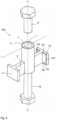
- Fig.6 shows an exploded view of the shear anchor 201 from Fig.5 with head bolts 14, whereby the load introduction prevention section 3 is not shown.
- the central connection section 2 in the form of a sleeve has two mounting points 15 for the webs of the head bolt 14, which can either be seen as welds or can also represent threads into which the head bolts can be screwed.
- the webs 241 and 242 can thus be particularly easily attached to a sleeve located between the load introduction sections 251 and 252.
- the connection section 2 can also be designed in another way, as long as a connection element can be connected to it in a materially bonded, positively bonded or force-locked manner to introduce forces into the shear force anchor 1.
- the connection section can also be designed as a flange.
- a plastic cap 16 which serves as a load introduction prevention section 3 for the Fig.6 shown shear anchor 201 is suitable.
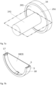
- Fig. 7a shows the first load introduction section 251, which is connected to the web 241 and the plastic cap 16, which is attached to the first load introduction section.
- Fig. 7b shows the plastic cap 16 in half section according to the Fig. 7a drawn cutting plane.
- Such a plastic cap 16 can be provided on the load introduction section 251 with the help of the click elements 17, which are attached inside the plastic cap in the circumferential direction.
- the click elements 17 are connected to the outer surface of the plastic cap 16 via a web-shaped connection 18.
- the plastic cap 16 is thus an example of a load introduction prevention section in which a gap exists at least partially as a load introduction prevention section 3.
- the plastic cap 16 integrally has the gap that serves as a load introduction prevention section 3 and thus the plastic cap 16 itself functions as a load introduction prevention section 3.
- a gap can be provided between the shear force anchor and the component by, for example, applying a self-dissolving material to the shear force anchor.
- Such plastic caps can also be provided in a similar way for other sections of the shear force anchor 201, for example for the webs 241 and 242.
- Such plastic caps can be produced using an injection molding process, which is why other shapes of the plastic cap can also be realized.
- the plastic cap can also be used for the shear force anchors 1 and 102 with cuboid load introduction sections 51 and 52.
- Fig.8 shows a perspective view of a modified shear force anchor not according to the invention, similar to the first and second embodiments with cuboid load introduction sections 51 and 52.
- two parallel load introduction sections 51 and 52 are connected, for example, via a sleeve-shaped hollow cylinder as a connection section 2 with or without an internal thread.
- a connection element can be provided in the connection section 2 via a bore 19 in the load introduction sections 51 and 52.
- These anchors can be used, for example, as a connection or
- Punching shear reinforcement for supports, columns, etc. are also suitable for transmitting opposing transverse forces transverse to the longitudinal direction of the component, whereby the axis of the connection section 2 lies in the direction of the respective transverse forces to be transmitted, but the connection section itself is spaced from the respective load introduction sections in the direction of the respective transverse force to be transmitted.
- Fig.9 shows a modified shear force anchor not according to the invention with cylindrical load introduction sections 251 and 252 similar to the third embodiment.
- the elastic layer as a load introduction prevention section is not shown.
- such a shear force anchor is superior to conventional connecting means, since by spacing the connection section from the load introduction section in the direction of the respective shear force to be transmitted, at least one force component in the direction of the shear force to be transmitted is transmitted into the component over a large component thickness.
- the shear anchors according to Fig. 8 and 9 are used as a connection for punching shear reinforcement, for example.
- a load introduction prevention section in the form of an elastic layer is advantageous.
- this anchor is loaded with a shear force
- the load introduction surfaces are subjected to compression in the direction in which the shear force acts.
- this compression load is then absorbed by the elastic layers and is not introduced into the concrete underneath, making punching difficult.
- the force is introduced directly into the component. Due to the deep anchoring, high forces can be absorbed without punching.
- the shear anchors according to the invention are also advantageous for lifting and erecting horizontally positioned precast concrete elements. Due to the load introduction areas, the effective shear forces are introduced into the component over a large part of the component thickness and the concrete can be used more effectively without the anchors tearing out of the concrete.
- such an anchor can also be provided with more than two load introduction sections, for example four.
- Such an anchor can transfer shear force not only along one axis, but along two axes.
Landscapes
- Engineering & Computer Science (AREA)
- Architecture (AREA)
- Physics & Mathematics (AREA)
- Electromagnetism (AREA)
- Civil Engineering (AREA)
- Structural Engineering (AREA)
- Joining Of Building Structures In Genera (AREA)
Claims (11)
- Ancrage pour forces transversales (1, 101, 201) destiné à transmettre des forces transversales transversalement à la direction longitudinale d'un composant (10) dans des composants constitués principalement de béton, comprenant : une section de connexion (2) pour appliquer au moins une force transversale dans l'ancrage pour forces transversales (1, 101, 201), dans lequel la section de connexion (2) est un tube, et au moins une section d'application de charge (51, 251) qui est reliée à la section de connexion (2) et qui peut être mise en contact avec le composant (10), afin de transmettre au moins une composante de force au composant (10) en direction de la force transversale à transmettre, dans lequel la section de connexion (2) est espacée de la section d'application de charge (51, 251) en direction de la force transversale à transmettre, caractérisé en ce quel'ancrage pour forces transversales (1, 101, 201) comporte en outre au moins une section de prévention d'application de charge (3), qui évite partiellement, ou de préférence complètement, une transmission de force dans le composant avec respectivement une composante en direction de la force transversale à transmettre via la section d'application de charge respective (51, 52, 251, 252), etla section de prévention d'application de charge (3) est pourvue partiellement sur la section d'application de charge respective (51, 52, 251, 252) et au moins partiellement sur la section de connexion (2).
- Ancrage pour forces transversales (1, 101, 201) selon la revendication 1, dans lequel l'ancrage pour forces transversales (1, 101, 201) comporte deux sections d'application de charge (51, 52, 251, 252) pour transmettre des forces transversales opposées, dans lequel la première section d'application de charge (51, 251) peut transmettre une composante de force en direction des forces transversales à transmettre dans le composant (10), et la deuxième section d'application de charge (52, 252) peut transmettre une composante de force en direction opposée aux forces transversales à transmettre dans le composant (10) et est espacée de la première section d'application de charge (51, 251) dans ladite direction des forces transversales à transmettre, et dans lequel la section de connexion (2) est reliée aux deux sections d'application de charge (51, 52, 251, 252).
- Ancrage pour forces transversales (1, 101, 201) selon l'une des revendications précédentes, dans lequel la section de prévention d'application de charge (3) est espacée de la section d'application de charge respective (51, 52, 251, 252) en direction de la force transversale à transmettre respective.
- Ancrage pour forces transversales (1, 101, 201) selon l'une des revendications précédentes, dans lequel la composante de force à transmettre de la section d'application de charge respective (51, 52, 251, 252) dans le composant (10) en direction de la force transversale à transmettre respective est supérieure à la composante de force à transmettre de la section de prévention d'application de charge (3) dans le composant (10) en direction de la force transversale à transmettre respective.
- Ancrage pour forces transversales (1, 101, 201) selon l'une des revendications précédentes, dans lequel la section d'application de charge respective (51, 52, 251, 252) présente au moins une surface d'application de charge (61, 261) qui peut être mise en contact avec le composant (10) et dont la normale à la surface d'attaque comporte une composante en direction de la force transversale à transmettre respective, mais de préférence les surfaces d'application de charge (61, 62, 261) de la section d'application de charge respective (51, 52, 251, 252) sont perpendiculaires à la direction de la force transversale à transmettre respective, et/ou les multiples surfaces d'application de charge (61, 62, 261) de la section d'application de charge respective (51, 52, 251, 252) sont situées dans un même plan.
- Ancrage pour forces transversales (1, 101, 201) selon l'une des revendications précédentes, caractérisé en ce que la section de prévention d'application de charge (3) est pourvue au moins partiellement sur toutes les surfaces (63) allant des surfaces d'application de charge (61, 62, 261) de la section d'application de charge respective (51, 52, 251, 252) en direction de la force transversale à transmettre respective et dont les normales à la surface d'attaque ont une composante en direction de la force transversale à transmettre respective.
- Ancrage pour forces transversales (1, 101, 201) selon l'une des revendications précédentes, dans lequel la section de prévention d'application de charge (3) est pourvue sur toutes les surfaces, à l'exception des surfaces d'application de charge (61, 62, 261) de la section d'application de charge respective (51, 52, 251, 252).
- Ancrage pour forces transversales (1, 101, 201) selon l'une des revendications 2 à 7, dans lequel une âme (41, 42, 241, 242) qui assure la liaison avec le section d'application de charge respective (51, 52, 251, 252) s'étend de deux côtés depuis la section de connexion (2).
- Ancrage pour forces transversales (1, 101, 201) selon l'une des revendications précédentes, dans lequel la section de prévention d'application de charge (3) est constituée d'un matériau élastique compressible, de préférence de mousse à cellules fermées.
- Ancrage pour forces transversales (1, 101, 201) selon la revendication 8, dans lequel la section de connexion (2), les sections d'application de charge respectives (51, 52, 251, 252) et les âmes (41, 42) sont constituées d'un matériau plus rigide que celui de la section de prévention d'application de charge (3), et de préférence d'acier galvanisé.
- Structure de liaison constituée d'un composant (10) et d'un ancrage pour forces transversales (1, 101, 201) selon l'une des revendications précédentes, dans laquelle la section de prévention d'application de charge (3) est pourvue au moins partiellement sous forme d'un intervalle entre le composant (10) et l'ancrage pour forces transversales (1, 101, 201).
Applications Claiming Priority (1)
| Application Number | Priority Date | Filing Date | Title |
|---|---|---|---|
| PCT/EP2018/061459 WO2019210968A1 (fr) | 2018-05-04 | 2018-05-04 | Système d'ancrage à force transversale |
Publications (3)
| Publication Number | Publication Date |
|---|---|
| EP3788210A1 EP3788210A1 (fr) | 2021-03-10 |
| EP3788210B1 true EP3788210B1 (fr) | 2024-05-01 |
| EP3788210C0 EP3788210C0 (fr) | 2024-05-01 |
Family
ID=62165542
Family Applications (1)
| Application Number | Title | Priority Date | Filing Date |
|---|---|---|---|
| EP18724500.6A Active EP3788210B1 (fr) | 2018-05-04 | 2018-05-04 | Système d'ancrage à force transversale |
Country Status (7)
| Country | Link |
|---|---|
| US (1) | US11486131B2 (fr) |
| EP (1) | EP3788210B1 (fr) |
| JP (1) | JP7111391B2 (fr) |
| CN (1) | CN112119192B (fr) |
| RU (1) | RU2753333C1 (fr) |
| TW (1) | TWI753253B (fr) |
| WO (1) | WO2019210968A1 (fr) |
Families Citing this family (1)
| Publication number | Priority date | Publication date | Assignee | Title |
|---|---|---|---|---|
| CA222547S (en) * | 2023-06-20 | 2024-09-06 | Sayfa R&D Pty Ltd | Tension anchor |
Family Cites Families (19)
| Publication number | Priority date | Publication date | Assignee | Title |
|---|---|---|---|---|
| US1511542A (en) * | 1921-01-27 | 1924-10-14 | Edward Ogden J | Concrete insert |
| SU657138A1 (ru) * | 1972-02-29 | 1979-04-15 | Berniker Yakov S | Закладна деталь |
| DE3312458A1 (de) | 1983-04-07 | 1984-10-11 | Pfeifer Seil- Und Hebetechnik Gmbh & Co, 8940 Memmingen | Transportanker fuer betonfertigteile |
| CH684201A5 (de) | 1991-12-05 | 1994-07-29 | Reto Bonomo | Schubdornkastenelement und dessen Verwendung. |
| RU2040648C1 (ru) * | 1993-06-24 | 1995-07-25 | Научно-исследовательский, проектно-конструкторский и технологический институт бетона и железобетона | Закладная деталь |
| JP2000248638A (ja) | 1999-02-26 | 2000-09-12 | Hitachi Zosen Corp | テーパジベル |
| DE20012824U1 (de) | 2000-07-25 | 2001-01-11 | Schnabel, Winfried, Dipl.-Ing., 61191 Rosbach | Fest-/Losflansch-Konstruktion bzw. nur Losflansch-Konstruktion zur Aufnahme von Horizontalkräften und Schrägzugkräften |
| JP3826348B2 (ja) | 2002-03-07 | 2006-09-27 | 清水建設株式会社 | 山留め芯材と地下外壁との合成壁の施工方法 |
| EP1477620B1 (fr) * | 2003-05-12 | 2006-09-13 | Ankaba Ankertechnik und Bauhandel AG | Dispositif d'ancrage pour éléments de construction en béton et son utilisation |
| US7445192B2 (en) * | 2004-06-14 | 2008-11-04 | Simpson Strong-Tie Company, Inc. | Shear wall template |
| CN100347390C (zh) | 2005-01-31 | 2007-11-07 | 常华北 | 锚栓及钢筋混凝土结构件外锚钢加固方法 |
| US8336267B2 (en) | 2008-10-31 | 2012-12-25 | Simpson Strong-Tie Company, Inc. | Construction frame shear lug |
| CA3090083C (fr) * | 2011-03-18 | 2023-09-19 | Thomas M. Espinosa | Ensemble d'accouplement pour ancrage a beton et support de tige d'ancrage |
| KR20130050634A (ko) * | 2011-11-08 | 2013-05-16 | (주)세종알앤디 | 철근 콘크리트 구조물을 위한 전단보강재 |
| KR101283436B1 (ko) * | 2011-12-19 | 2013-07-09 | 이재호 | 플레이트 용접방식의 앵커 채널 및 그의 제조방법 |
| KR101302458B1 (ko) * | 2012-10-11 | 2013-09-02 | 이재호 | 서브 앵커를 갖는 선시공 앵커 채널 |
| CH707321A1 (de) * | 2012-12-12 | 2014-06-13 | Spaeter Zug Ag | Dehnfugenkonstruktionselement. |
| JP6441063B2 (ja) | 2014-12-18 | 2018-12-19 | 大和ハウス工業株式会社 | 補強金物および建物基礎構造 |
| CN104818723B (zh) | 2015-05-07 | 2016-07-27 | 重庆交通大学 | 边坡支护用抗滑桩 |
-
2018
- 2018-05-04 RU RU2020134751A patent/RU2753333C1/ru active
- 2018-05-04 EP EP18724500.6A patent/EP3788210B1/fr active Active
- 2018-05-04 JP JP2020561640A patent/JP7111391B2/ja active Active
- 2018-05-04 CN CN201880093156.5A patent/CN112119192B/zh active Active
- 2018-05-04 WO PCT/EP2018/061459 patent/WO2019210968A1/fr not_active Ceased
- 2018-05-04 US US17/052,712 patent/US11486131B2/en active Active
-
2019
- 2019-05-06 TW TW108115562A patent/TWI753253B/zh not_active IP Right Cessation
Also Published As
| Publication number | Publication date |
|---|---|
| WO2019210968A1 (fr) | 2019-11-07 |
| JP7111391B2 (ja) | 2022-08-02 |
| CN112119192A (zh) | 2020-12-22 |
| EP3788210A1 (fr) | 2021-03-10 |
| CN112119192B (zh) | 2022-04-19 |
| JP2021522432A (ja) | 2021-08-30 |
| TW202006220A (zh) | 2020-02-01 |
| RU2753333C1 (ru) | 2021-08-13 |
| US11486131B2 (en) | 2022-11-01 |
| US20210180316A1 (en) | 2021-06-17 |
| EP3788210C0 (fr) | 2024-05-01 |
| TWI753253B (zh) | 2022-01-21 |
Similar Documents
| Publication | Publication Date | Title |
|---|---|---|
| EP3695062B1 (fr) | Élément d'ancrage, pièce en béton pourvue d'un élément d'ancrage et procédé de fabrication | |
| EP3057774B1 (fr) | Pièce munie d'une partie fixation permettant un assemblage par vis et pièce moulée et élément de fixation | |
| WO2006103033A2 (fr) | Clavette pour relier au moins deux elements de construction, et systeme d'elements de construction relies les uns aux autres | |
| EP0059171B1 (fr) | Boulon et canon pour la prise et la transmission d'une force transversale | |
| EP1216332B1 (fr) | Systeme de liaison destine a la fixation rigide d'au moins deux elements | |
| EP0984177B1 (fr) | Vis d'assemblage pour structure combinée bois-béton | |
| DE102019002620B4 (de) | Verbindungssystem für Holz-, Holz-Beton - oder Metallkonstruktionen | |
| EP1745182A1 (fr) | Element de connexion de dalle en console | |
| EP3788210B1 (fr) | Système d'ancrage à force transversale | |
| EP3225758B1 (fr) | Élément de raccordement d'isolement thermique entre un élément de bâtiment vertical et un élément de bâtiment horizontal | |
| EP2130984A2 (fr) | Corps de répartition de charge doté d'un système de support de profil | |
| DE102007013509A1 (de) | Befestigungsvorrichtung | |
| WO2005035892A1 (fr) | Dispositif comprenant une barre en plastique renforce par des fibres et servant a transmettre une charge a travers une couche calorifuge | |
| EP1505218B1 (fr) | Système composite d'isolation thermique | |
| DE19636447C1 (de) | Montageteil für die Befestigung von Bauteilen an mit einer Dämmschicht versehenen Wänden, Decken o. dgl. Flächen | |
| EP3211146B1 (fr) | Systeme de liaison pour une construction en bois | |
| EP2982807B1 (fr) | Dispositif destiné à relier deux composants séparés par un joint | |
| EP1932978B1 (fr) | Elément d'armature pour l'absorption de forces dans des plaques de béton dans la zone d'éléments d'appui | |
| EP0810334A1 (fr) | Elément de construction pour isolation thermique | |
| CH634388A5 (de) | Befestigungselement zum anbringen an einer wand oder einem wandelement die bzw. das hohlraeume oder rueckseitig schwer zugaengliche stellen aufweist. | |
| DE3218457C2 (de) | Dübelbefestigung für Treppenstufen | |
| EP2998454A1 (fr) | Dispositif destine a relier deux parties de batiment separees par un joint | |
| EP3835501B1 (fr) | Arrangement pour connecter une pièce de construction avec une partie extérieure frontale | |
| DE202013104418U1 (de) | Fassadenkonsole sowie Fassadenkonstruktion | |
| DE202019001629U1 (de) | Verbindungssystem für Holz- und/oder Metallkonstruktionen |
Legal Events
| Date | Code | Title | Description |
|---|---|---|---|
| STAA | Information on the status of an ep patent application or granted ep patent |
Free format text: STATUS: UNKNOWN |
|
| STAA | Information on the status of an ep patent application or granted ep patent |
Free format text: STATUS: THE INTERNATIONAL PUBLICATION HAS BEEN MADE |
|
| PUAI | Public reference made under article 153(3) epc to a published international application that has entered the european phase |
Free format text: ORIGINAL CODE: 0009012 |
|
| STAA | Information on the status of an ep patent application or granted ep patent |
Free format text: STATUS: REQUEST FOR EXAMINATION WAS MADE |
|
| 17P | Request for examination filed |
Effective date: 20201204 |
|
| AK | Designated contracting states |
Kind code of ref document: A1 Designated state(s): AL AT BE BG CH CY CZ DE DK EE ES FI FR GB GR HR HU IE IS IT LI LT LU LV MC MK MT NL NO PL PT RO RS SE SI SK SM TR |
|
| AX | Request for extension of the european patent |
Extension state: BA ME |
|
| DAV | Request for validation of the european patent (deleted) | ||
| DAX | Request for extension of the european patent (deleted) | ||
| STAA | Information on the status of an ep patent application or granted ep patent |
Free format text: STATUS: EXAMINATION IS IN PROGRESS |
|
| 17Q | First examination report despatched |
Effective date: 20230328 |
|
| GRAP | Despatch of communication of intention to grant a patent |
Free format text: ORIGINAL CODE: EPIDOSNIGR1 |
|
| STAA | Information on the status of an ep patent application or granted ep patent |
Free format text: STATUS: GRANT OF PATENT IS INTENDED |
|
| INTG | Intention to grant announced |
Effective date: 20231214 |
|
| GRAS | Grant fee paid |
Free format text: ORIGINAL CODE: EPIDOSNIGR3 |
|
| GRAA | (expected) grant |
Free format text: ORIGINAL CODE: 0009210 |
|
| STAA | Information on the status of an ep patent application or granted ep patent |
Free format text: STATUS: THE PATENT HAS BEEN GRANTED |
|
| AK | Designated contracting states |
Kind code of ref document: B1 Designated state(s): AL AT BE BG CH CY CZ DE DK EE ES FI FR GB GR HR HU IE IS IT LI LT LU LV MC MK MT NL NO PL PT RO RS SE SI SK SM TR |
|
| REG | Reference to a national code |
Ref country code: GB Ref legal event code: FG4D Free format text: NOT ENGLISH |
|
| REG | Reference to a national code |
Ref country code: CH Ref legal event code: EP |
|
| REG | Reference to a national code |
Ref country code: DE Ref legal event code: R096 Ref document number: 502018014542 Country of ref document: DE |
|
| REG | Reference to a national code |
Ref country code: IE Ref legal event code: FG4D Free format text: LANGUAGE OF EP DOCUMENT: GERMAN |
|
| U01 | Request for unitary effect filed |
Effective date: 20240502 |
|
| U07 | Unitary effect registered |
Designated state(s): AT BE BG DE DK EE FI FR IT LT LU LV MT NL PT SE SI Effective date: 20240516 |
|
| U20 | Renewal fee for the european patent with unitary effect paid |
Year of fee payment: 7 Effective date: 20240527 |
|
| PG25 | Lapsed in a contracting state [announced via postgrant information from national office to epo] |
Ref country code: IS Free format text: LAPSE BECAUSE OF FAILURE TO SUBMIT A TRANSLATION OF THE DESCRIPTION OR TO PAY THE FEE WITHIN THE PRESCRIBED TIME-LIMIT Effective date: 20240901 |
|
| PG25 | Lapsed in a contracting state [announced via postgrant information from national office to epo] |
Ref country code: HR Free format text: LAPSE BECAUSE OF FAILURE TO SUBMIT A TRANSLATION OF THE DESCRIPTION OR TO PAY THE FEE WITHIN THE PRESCRIBED TIME-LIMIT Effective date: 20240501 |
|
| PG25 | Lapsed in a contracting state [announced via postgrant information from national office to epo] |
Ref country code: GR Free format text: LAPSE BECAUSE OF FAILURE TO SUBMIT A TRANSLATION OF THE DESCRIPTION OR TO PAY THE FEE WITHIN THE PRESCRIBED TIME-LIMIT Effective date: 20240802 |
|
| PG25 | Lapsed in a contracting state [announced via postgrant information from national office to epo] |
Ref country code: ES Free format text: LAPSE BECAUSE OF FAILURE TO SUBMIT A TRANSLATION OF THE DESCRIPTION OR TO PAY THE FEE WITHIN THE PRESCRIBED TIME-LIMIT Effective date: 20240501 |
|
| PG25 | Lapsed in a contracting state [announced via postgrant information from national office to epo] |
Ref country code: PL Free format text: LAPSE BECAUSE OF FAILURE TO SUBMIT A TRANSLATION OF THE DESCRIPTION OR TO PAY THE FEE WITHIN THE PRESCRIBED TIME-LIMIT Effective date: 20240501 |
|
| PG25 | Lapsed in a contracting state [announced via postgrant information from national office to epo] |
Ref country code: PL Free format text: LAPSE BECAUSE OF FAILURE TO SUBMIT A TRANSLATION OF THE DESCRIPTION OR TO PAY THE FEE WITHIN THE PRESCRIBED TIME-LIMIT Effective date: 20240501 Ref country code: NO Free format text: LAPSE BECAUSE OF FAILURE TO SUBMIT A TRANSLATION OF THE DESCRIPTION OR TO PAY THE FEE WITHIN THE PRESCRIBED TIME-LIMIT Effective date: 20240801 Ref country code: IS Free format text: LAPSE BECAUSE OF FAILURE TO SUBMIT A TRANSLATION OF THE DESCRIPTION OR TO PAY THE FEE WITHIN THE PRESCRIBED TIME-LIMIT Effective date: 20240901 Ref country code: HR Free format text: LAPSE BECAUSE OF FAILURE TO SUBMIT A TRANSLATION OF THE DESCRIPTION OR TO PAY THE FEE WITHIN THE PRESCRIBED TIME-LIMIT Effective date: 20240501 Ref country code: GR Free format text: LAPSE BECAUSE OF FAILURE TO SUBMIT A TRANSLATION OF THE DESCRIPTION OR TO PAY THE FEE WITHIN THE PRESCRIBED TIME-LIMIT Effective date: 20240802 Ref country code: ES Free format text: LAPSE BECAUSE OF FAILURE TO SUBMIT A TRANSLATION OF THE DESCRIPTION OR TO PAY THE FEE WITHIN THE PRESCRIBED TIME-LIMIT Effective date: 20240501 Ref country code: RS Free format text: LAPSE BECAUSE OF FAILURE TO SUBMIT A TRANSLATION OF THE DESCRIPTION OR TO PAY THE FEE WITHIN THE PRESCRIBED TIME-LIMIT Effective date: 20240801 |
|
| REG | Reference to a national code |
Ref country code: CH Ref legal event code: PL |
|
| PG25 | Lapsed in a contracting state [announced via postgrant information from national office to epo] |
Ref country code: CZ Free format text: LAPSE BECAUSE OF FAILURE TO SUBMIT A TRANSLATION OF THE DESCRIPTION OR TO PAY THE FEE WITHIN THE PRESCRIBED TIME-LIMIT Effective date: 20240501 |
|
| PG25 | Lapsed in a contracting state [announced via postgrant information from national office to epo] |
Ref country code: SK Free format text: LAPSE BECAUSE OF FAILURE TO SUBMIT A TRANSLATION OF THE DESCRIPTION OR TO PAY THE FEE WITHIN THE PRESCRIBED TIME-LIMIT Effective date: 20240501 Ref country code: RO Free format text: LAPSE BECAUSE OF FAILURE TO SUBMIT A TRANSLATION OF THE DESCRIPTION OR TO PAY THE FEE WITHIN THE PRESCRIBED TIME-LIMIT Effective date: 20240501 |
|
| PG25 | Lapsed in a contracting state [announced via postgrant information from national office to epo] |
Ref country code: SM Free format text: LAPSE BECAUSE OF FAILURE TO SUBMIT A TRANSLATION OF THE DESCRIPTION OR TO PAY THE FEE WITHIN THE PRESCRIBED TIME-LIMIT Effective date: 20240501 |
|
| PG25 | Lapsed in a contracting state [announced via postgrant information from national office to epo] |
Ref country code: SM Free format text: LAPSE BECAUSE OF FAILURE TO SUBMIT A TRANSLATION OF THE DESCRIPTION OR TO PAY THE FEE WITHIN THE PRESCRIBED TIME-LIMIT Effective date: 20240501 Ref country code: SK Free format text: LAPSE BECAUSE OF FAILURE TO SUBMIT A TRANSLATION OF THE DESCRIPTION OR TO PAY THE FEE WITHIN THE PRESCRIBED TIME-LIMIT Effective date: 20240501 Ref country code: RO Free format text: LAPSE BECAUSE OF FAILURE TO SUBMIT A TRANSLATION OF THE DESCRIPTION OR TO PAY THE FEE WITHIN THE PRESCRIBED TIME-LIMIT Effective date: 20240501 Ref country code: CZ Free format text: LAPSE BECAUSE OF FAILURE TO SUBMIT A TRANSLATION OF THE DESCRIPTION OR TO PAY THE FEE WITHIN THE PRESCRIBED TIME-LIMIT Effective date: 20240501 Ref country code: CH Free format text: LAPSE BECAUSE OF NON-PAYMENT OF DUE FEES Effective date: 20240531 Ref country code: MC Free format text: LAPSE BECAUSE OF FAILURE TO SUBMIT A TRANSLATION OF THE DESCRIPTION OR TO PAY THE FEE WITHIN THE PRESCRIBED TIME-LIMIT Effective date: 20240501 |
|
| REG | Reference to a national code |
Ref country code: DE Ref legal event code: R097 Ref document number: 502018014542 Country of ref document: DE |
|
| PLBE | No opposition filed within time limit |
Free format text: ORIGINAL CODE: 0009261 |
|
| STAA | Information on the status of an ep patent application or granted ep patent |
Free format text: STATUS: NO OPPOSITION FILED WITHIN TIME LIMIT |
|
| 26N | No opposition filed |
Effective date: 20250204 |
|
| PG25 | Lapsed in a contracting state [announced via postgrant information from national office to epo] |
Ref country code: IE Free format text: LAPSE BECAUSE OF NON-PAYMENT OF DUE FEES Effective date: 20240504 |
|
| GBPC | Gb: european patent ceased through non-payment of renewal fee |
Effective date: 20240801 |
|
| U20 | Renewal fee for the european patent with unitary effect paid |
Year of fee payment: 8 Effective date: 20250528 |
|
| PG25 | Lapsed in a contracting state [announced via postgrant information from national office to epo] |
Ref country code: GB Free format text: LAPSE BECAUSE OF NON-PAYMENT OF DUE FEES Effective date: 20240801 |
|
| PG25 | Lapsed in a contracting state [announced via postgrant information from national office to epo] |
Ref country code: CY Free format text: LAPSE BECAUSE OF FAILURE TO SUBMIT A TRANSLATION OF THE DESCRIPTION OR TO PAY THE FEE WITHIN THE PRESCRIBED TIME-LIMIT; INVALID AB INITIO Effective date: 20180504 |
|
| PG25 | Lapsed in a contracting state [announced via postgrant information from national office to epo] |
Ref country code: HU Free format text: LAPSE BECAUSE OF FAILURE TO SUBMIT A TRANSLATION OF THE DESCRIPTION OR TO PAY THE FEE WITHIN THE PRESCRIBED TIME-LIMIT; INVALID AB INITIO Effective date: 20180504 |
|
| U20 | Renewal fee for the european patent with unitary effect paid |
Year of fee payment: 9 Effective date: 20260312 |