EP2363302A1 - Dispositif de liaison d'un élément de ressort sur un essieu de véhicule utilitaire - Google Patents
Dispositif de liaison d'un élément de ressort sur un essieu de véhicule utilitaire Download PDFInfo
- Publication number
- EP2363302A1 EP2363302A1 EP10015757A EP10015757A EP2363302A1 EP 2363302 A1 EP2363302 A1 EP 2363302A1 EP 10015757 A EP10015757 A EP 10015757A EP 10015757 A EP10015757 A EP 10015757A EP 2363302 A1 EP2363302 A1 EP 2363302A1
- Authority
- EP
- European Patent Office
- Prior art keywords
- axle body
- axle
- commercial vehicle
- abutment
- fixing projection
- Prior art date
- Legal status (The legal status is an assumption and is not a legal conclusion. Google has not performed a legal analysis and makes no representation as to the accuracy of the status listed.)
- Granted
Links
Images


Classifications
-
- B—PERFORMING OPERATIONS; TRANSPORTING
- B60—VEHICLES IN GENERAL
- B60B—VEHICLE WHEELS; CASTORS; AXLES FOR WHEELS OR CASTORS; INCREASING WHEEL ADHESION
- B60B35/00—Axle units; Parts thereof ; Arrangements for lubrication of axles
- B60B35/12—Torque-transmitting axles
- B60B35/16—Axle housings
- B60B35/163—Axle housings characterised by specific shape of the housing, e.g. adaptations to give space for other vehicle elements like chassis or exhaust system
-
- B—PERFORMING OPERATIONS; TRANSPORTING
- B60—VEHICLES IN GENERAL
- B60B—VEHICLE WHEELS; CASTORS; AXLES FOR WHEELS OR CASTORS; INCREASING WHEEL ADHESION
- B60B35/00—Axle units; Parts thereof ; Arrangements for lubrication of axles
- B60B35/003—Steerable axles
-
- B—PERFORMING OPERATIONS; TRANSPORTING
- B60—VEHICLES IN GENERAL
- B60B—VEHICLE WHEELS; CASTORS; AXLES FOR WHEELS OR CASTORS; INCREASING WHEEL ADHESION
- B60B35/00—Axle units; Parts thereof ; Arrangements for lubrication of axles
- B60B35/004—Mounting arrangements for axles
- B60B35/006—Mounting arrangements for axles with mounting plates or consoles fitted to axles
- B60B35/007—Mounting arrangements for axles with mounting plates or consoles fitted to axles for mounting suspension elements to axles
-
- B—PERFORMING OPERATIONS; TRANSPORTING
- B60—VEHICLES IN GENERAL
- B60G—VEHICLE SUSPENSION ARRANGEMENTS
- B60G11/00—Resilient suspensions characterised by arrangement, location or kind of springs
- B60G11/02—Resilient suspensions characterised by arrangement, location or kind of springs having leaf springs only
- B60G11/04—Resilient suspensions characterised by arrangement, location or kind of springs having leaf springs only arranged substantially parallel to the longitudinal axis of the vehicle
-
- B—PERFORMING OPERATIONS; TRANSPORTING
- B60—VEHICLES IN GENERAL
- B60G—VEHICLE SUSPENSION ARRANGEMENTS
- B60G11/00—Resilient suspensions characterised by arrangement, location or kind of springs
- B60G11/02—Resilient suspensions characterised by arrangement, location or kind of springs having leaf springs only
- B60G11/10—Resilient suspensions characterised by arrangement, location or kind of springs having leaf springs only characterised by means specially adapted for attaching the spring to axle or sprung part of the vehicle
- B60G11/113—Mountings on the axle
-
- B—PERFORMING OPERATIONS; TRANSPORTING
- B60—VEHICLES IN GENERAL
- B60G—VEHICLE SUSPENSION ARRANGEMENTS
- B60G9/00—Resilient suspensions of a rigid axle or axle housing for two or more wheels
-
- B—PERFORMING OPERATIONS; TRANSPORTING
- B60—VEHICLES IN GENERAL
- B60B—VEHICLE WHEELS; CASTORS; AXLES FOR WHEELS OR CASTORS; INCREASING WHEEL ADHESION
- B60B2310/00—Manufacturing methods
- B60B2310/30—Manufacturing methods joining
- B60B2310/306—Manufacturing methods joining by clamping or wedging, e.g. by clamping inserts as joining means
-
- B—PERFORMING OPERATIONS; TRANSPORTING
- B60—VEHICLES IN GENERAL
- B60G—VEHICLE SUSPENSION ARRANGEMENTS
- B60G2200/00—Indexing codes relating to suspension types
- B60G2200/30—Rigid axle suspensions
-
- B—PERFORMING OPERATIONS; TRANSPORTING
- B60—VEHICLES IN GENERAL
- B60G—VEHICLE SUSPENSION ARRANGEMENTS
- B60G2200/00—Indexing codes relating to suspension types
- B60G2200/40—Indexing codes relating to the wheels in the suspensions
- B60G2200/422—Driving wheels or live axles
-
- B—PERFORMING OPERATIONS; TRANSPORTING
- B60—VEHICLES IN GENERAL
- B60G—VEHICLE SUSPENSION ARRANGEMENTS
- B60G2202/00—Indexing codes relating to the type of spring, damper or actuator
- B60G2202/10—Type of spring
- B60G2202/11—Leaf spring
- B60G2202/112—Leaf spring longitudinally arranged
-
- B—PERFORMING OPERATIONS; TRANSPORTING
- B60—VEHICLES IN GENERAL
- B60G—VEHICLE SUSPENSION ARRANGEMENTS
- B60G2204/00—Indexing codes related to suspensions per se or to auxiliary parts
- B60G2204/10—Mounting of suspension elements
- B60G2204/12—Mounting of springs or dampers
- B60G2204/121—Mounting of leaf springs
-
- B—PERFORMING OPERATIONS; TRANSPORTING
- B60—VEHICLES IN GENERAL
- B60G—VEHICLE SUSPENSION ARRANGEMENTS
- B60G2204/00—Indexing codes related to suspensions per se or to auxiliary parts
- B60G2204/10—Mounting of suspension elements
- B60G2204/14—Mounting of suspension arms
- B60G2204/148—Mounting of suspension arms on the unsprung part of the vehicle, e.g. wheel knuckle or rigid axle
-
- B—PERFORMING OPERATIONS; TRANSPORTING
- B60—VEHICLES IN GENERAL
- B60G—VEHICLE SUSPENSION ARRANGEMENTS
- B60G2204/00—Indexing codes related to suspensions per se or to auxiliary parts
- B60G2204/40—Auxiliary suspension parts; Adjustment of suspensions
- B60G2204/43—Fittings, brackets or knuckles
- B60G2204/4306—Bracket or knuckle for rigid axles, e.g. for clamping
-
- B—PERFORMING OPERATIONS; TRANSPORTING
- B60—VEHICLES IN GENERAL
- B60G—VEHICLE SUSPENSION ARRANGEMENTS
- B60G2204/00—Indexing codes related to suspensions per se or to auxiliary parts
- B60G2204/40—Auxiliary suspension parts; Adjustment of suspensions
- B60G2204/44—Centering or positioning means
-
- B—PERFORMING OPERATIONS; TRANSPORTING
- B60—VEHICLES IN GENERAL
- B60G—VEHICLE SUSPENSION ARRANGEMENTS
- B60G2206/00—Indexing codes related to the manufacturing of suspensions: constructional features, the materials used, procedures or tools
- B60G2206/01—Constructional features of suspension elements, e.g. arms, dampers, springs
- B60G2206/30—Constructional features of rigid axles
- B60G2206/32—Hollow cross section
-
- B—PERFORMING OPERATIONS; TRANSPORTING
- B60—VEHICLES IN GENERAL
- B60G—VEHICLE SUSPENSION ARRANGEMENTS
- B60G2206/00—Indexing codes related to the manufacturing of suspensions: constructional features, the materials used, procedures or tools
- B60G2206/01—Constructional features of suspension elements, e.g. arms, dampers, springs
- B60G2206/80—Manufacturing procedures
- B60G2206/81—Shaping
- B60G2206/8101—Shaping by casting
-
- B—PERFORMING OPERATIONS; TRANSPORTING
- B60—VEHICLES IN GENERAL
- B60G—VEHICLE SUSPENSION ARRANGEMENTS
- B60G2206/00—Indexing codes related to the manufacturing of suspensions: constructional features, the materials used, procedures or tools
- B60G2206/01—Constructional features of suspension elements, e.g. arms, dampers, springs
- B60G2206/80—Manufacturing procedures
- B60G2206/81—Shaping
- B60G2206/8102—Shaping by stamping
-
- B—PERFORMING OPERATIONS; TRANSPORTING
- B60—VEHICLES IN GENERAL
- B60G—VEHICLE SUSPENSION ARRANGEMENTS
- B60G2206/00—Indexing codes related to the manufacturing of suspensions: constructional features, the materials used, procedures or tools
- B60G2206/01—Constructional features of suspension elements, e.g. arms, dampers, springs
- B60G2206/80—Manufacturing procedures
- B60G2206/82—Joining
- B60G2206/8207—Joining by screwing
-
- B—PERFORMING OPERATIONS; TRANSPORTING
- B60—VEHICLES IN GENERAL
- B60G—VEHICLE SUSPENSION ARRANGEMENTS
- B60G2300/00—Indexing codes relating to the type of vehicle
- B60G2300/02—Trucks; Load vehicles
-
- B—PERFORMING OPERATIONS; TRANSPORTING
- B60—VEHICLES IN GENERAL
- B60Y—INDEXING SCHEME RELATING TO ASPECTS CROSS-CUTTING VEHICLE TECHNOLOGY
- B60Y2200/00—Type of vehicle
- B60Y2200/10—Road Vehicles
- B60Y2200/14—Trucks; Load vehicles, Busses
-
- B—PERFORMING OPERATIONS; TRANSPORTING
- B60—VEHICLES IN GENERAL
- B60Y—INDEXING SCHEME RELATING TO ASPECTS CROSS-CUTTING VEHICLE TECHNOLOGY
- B60Y2200/00—Type of vehicle
- B60Y2200/20—Off-Road Vehicles
- B60Y2200/22—Agricultural vehicles
-
- B—PERFORMING OPERATIONS; TRANSPORTING
- B60—VEHICLES IN GENERAL
- B60Y—INDEXING SCHEME RELATING TO ASPECTS CROSS-CUTTING VEHICLE TECHNOLOGY
- B60Y2200/00—Type of vehicle
- B60Y2200/20—Off-Road Vehicles
- B60Y2200/24—Military vehicles
Definitions
- the invention relates to a utility vehicle, with an axle body according to the preamble of patent claim 1.
- axle connection for spring-mounted vehicle axles has a preferably designed as a square tube with rounded edges axle body.
- the axle connection has trailing arms or leaf springs provided, which intersect the axle body at its top or bottom.
- tie rods are arranged, which extend transversely to the trailing arms or leaf springs as well as to the axle body and pull apart said parts against each other.
- the tie rods extend along the side walls of the axle body and are supported on an outer axis of the axle abutting axles.
- the tie rods are provided along their longitudinal extent with at least one bend or offset.
- the invention has for its object to provide a spring connection to an axle body, in which the introduction of force of the spring element in the axle body runs cheaper and the structure of the axle is thereby relieved.
- the invention comprises a tensioning bridge comprising at least two legs, which are connected to one another via at least one web, wherein an axle body extends between the legs. In the installed state, the tensioning bridge spans the axle body.
- the spring element is fixed by means of clamping devices on the upper side of the web of the clamping bridge.
- the clamping devices are attached to the abutment or on the fixing projection of the axle body.
- the tensioning bridge is adapted to the outer circumference of the axle body of the commercial vehicle axle.
- the invention enables the arrangement of a standardized clamping bridge on axle bodies with different shape and deviating diameter, so that the clamping bridge can be used on axle bodies with a hollow cross-section, U-profiles or double T-profiles.
- the lists are only exemplary and in no way exclusively meant.
- the clamping bridge according to the invention can rather be combined with any possible axle body shape. It is irrelevant whether it is a driven or a non-driven axle acts.
- the tensioning bridge proves to be advantageous because it resists high vertical forces and other tasks such.
- Conceivable are z. As leaf springs, coil springs, air springs or hydropneumatic suspensions, for example in the form of hydraulic cylinders. According to the invention, the web is spaced in the installed state of the axle.
- an abutment is arranged, which spans the axle body and thereby connects the legs together.
- the abutment serves for additional anchoring of the tensioning bridge on the axle body.
- the abutment on lateral walls which extend at an angle to the base of the abutment and are connectable to the legs of the clamping bridge and / or the web of the clamping bridge.
- the abutment and the clamping bridge can be screwed together or braced.
- other connection possibilities between the abutment and the clamping bridge are possible.
- At least one centering device is provided on the abutment and / or on the clamping bridge and / or on the fixing projection, which allow a positionally accurate arrangement of the clamping bridge relative to the abutment or a positionally accurate arrangement of the clamping bridge or the abutment relative to the axle body.
- the fixing projection is arranged in the region of the zero line of the axle body, ie in the region of the smallest bend on the axle body. It is conceivable that the fixing projections are mounted horizontally or angled transversely to the direction of travel on the axle body.
- the fixing projections may be cast in one piece with the axle body or forged to the axle body.
- a vertical force emanating from the spring element is directed over the leg of the tensioning bridge into the fixing projection of the axle body.
- the back of the axle body is freed in this way from the entry of high vertical loads, since the force acting on the axle body Compressive load flows homogeneously and laterally into the axle body. Due to the fact that the legs are connected to the fixing projections, the force introduction of the spring element is not directly from above on the back of the axle body. The back of the axle body is relieved of the vertical pressure exerted by the spring element, resulting in a significant extension of the life of the axle body.
- the fixing projection wedge-shaped wherein the upper, the web of the clamping bridge facing the end of the fixing projection forms a footprint for the leg, whereas the lower end of the fixing projection to the wider lower portion of the axle body out is rejuvenated.
- a further embodiment of the invention provides that the leg lower side and the profile of the fixing projection, on which the leg rests, are designed such that a mutual engagement between the leg lower side and the fixing projection is possible. As a result, a slip-proof attachment of the carrier profile is ensured on the fixing projection.
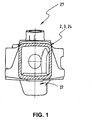
- Fig. 1 shows a connection device of a spring element (not shown) on an axle body 2 of a commercial vehicle axle 3 for vibration isolation of the chassis frame (not shown) relative to the vehicle axle 3 according to the prior art.
- the axle body 2 has an approximately rectangular shape 24, which receives the vehicle axle 3 in itself.
- With number 27 a receptacle for wheel carrier is shown.
- Fig. 2 shows in side view the axle body 2 of the commercial vehicle axle 3 with the Ausretesachskessel 22 and the Fix réellesvorsprüngen 8.
- the Fixtechniksvorsprüngen 8 and parallel to the Fix réellesvorsprüngen 8 on the axle 2 Zentrier wornen 21, 25 are provided, the positionally accurate arrangement of the clamping bridge 4 and the abutment 9 against each other and enable relative to the axle body 2.
- the axle body 2 receptacles 27 are provided for the wheel.
- the spine 10 of the axle body 2 can be seen, which is denoted by reference numeral 15 with respect to the lower region of the axle body 2.
- An imaginary line 28 runs along the fixing projection 8 and separates the axle body 2 into a back 10 and a lower region 15.
- the imaginary line 28 simultaneously marks the zero line 11, namely the region of the axle body 2 in which the bend is the smallest.
- Fig. 3 shows a section through the axle body 2 next to the clamping bridge 4 and the abutment 9 of the connection device according to the invention.
- the axle body 2 is trapezoidal and has a back 10 and a lower portion 15. in the Seen cross-section, the axle body 2 widens from the back 10 toward the lower region 15.
- the axis 3 of the utility vehicle can be seen.
- Fixianssvorsprünge 8 are attached approximately in the zero line 11 of the axle body 2 on the outer circumference of the axle body.
- the fixing protrusions 8 divide the axle body 2 into a spine 10 and a lower region 15.
- the fixing protrusion has a standing surface 30 on which the contact surface 18 of the leg 5 of the tensioning bridge 4 (not shown) is supported.
- the fixing projection 8 tapers from its upper end 16 to its lower end 17, so that the force in the downwardly widening region 15 of the axle body 2 is initiated.
- Centering 21 recognizable.
- a further centering device 25 is arranged, which serves to position the abutment 9 relative to the axle body 2.
- Fig. 4 shows an exploded view of an axle 2 with a arranged over the back 10 of the axle 2 tensioning bridge 4 and a recognizable below the axle body 2 abutment 9.
- the axle body 2 has a Ausretesachskessel 22 of the differential gear and at its outer end a receptacle 27 for the wheel ,
- the fixing projection 8 extends on the outer circumference of the axle body 2.
- the profile 14 of the fixing projection 8 shows an upper end 16 and a downwardly tapering lower end 17 and a centering device 21.
- the legs 5 of the clamping bridge 4 can be seen, between which the axle body 2 extends.
- the web 6 which has a receiving device 32 for a spring element 1, not shown.
- On the lower sides 13 of the legs 5 contact surfaces for the support of the legs 5 on the base surfaces 30 of the fixing projection 8 can be seen.
- lugs 33 are shown, which serve to position the legs 5 of the clamping bridge 4 on the centering device 21 of the fixing projection 8.
- 9 contact surfaces 34 are arranged on the abutment 9 for the abutment of the abutment 9 on the axle body. The centering of the abutment 9 relative to the centering device 21 of the fixing projection 8 via lugs 35 of the abutment 9.
- Fig. 5 shows a side view of the axle body 2 with the connecting device according to the invention in the installed state 40.
- the application device has a clamping bridge 4 and connected to the clamping bridge 4 abutment 9. From the side view of the leg 5 of the clamping bridge 4 can be seen, which rests with its footprint 18 on the fixing projection 8.
- the clamping bridge 4 is aligned over the lugs 33 on the centering device 21 of the fixing projection 8.
- the back 10 of the axle body 2 opposite the abutment 9 can be seen, the side walls 19 carry lugs 35 through which the abutment 9 is centered on the fixing projection 8.
- the abutment 9 rests with its contact surfaces 34 on the centering device 25 of the axle body 2 facing away from the back 10 of the axle body 2.
- Fig. 6 shows a perspective overall view of the inventive connecting device of a spring element 1 on an axle body 2 of a commercial vehicle axis 3.
- the tensioning bridge 4 and the abutment 9 are arranged for use on the axle body 2.
- On the top of the web 6 rests a leaf spring package 36 which is positioned on brackets 37 on the web 6, which are fixed to the abutment 9.
- the clamping bridge 4 is seated with the underside 13 of its legs 5 on the base surfaces 30 of the fixing projection 8. Comparable with the preceding figures, the clamping bridge 4 is aligned on the centering device 21 on the axle. Also comparable to the previous figures is the in Fig.
- abutment 9 with its base 20 on the centering device 25 of the axle body 2 positionally accurate.
- the axle body 2 extends in the Fig. 6 Transversely to the direction of travel 29.
- the spring element 1 extends in the form of a leaf spring package 36 in the direction of travel 29. Due to its positioning on the support surfaces 30 of the fixing projections 8, the clamping bridge 4 rises with its legs 5 on the axle body 2 of the commercial vehicle axis 3, so that the web 6 of the axle body 2 is spaced from the back 10 of the axle body 2 by a distance 38.
- Fig. 7 shows a section in the direction of travel 29 through the axle body 2 of the commercial vehicle axle 3 in the region of the connection according to the invention for the spring element 1 (not shown).
- the vehicle axle 3 runs in the interior of the axle body 2.
- the fixing projections 8 are shown.
- the direction of travel 29 protrude in height the zero line 11 of the axle body 2 on both sides of the fixing projections 8 from the axle body 2 of the commercial vehicle axle 3 out.
- the standing surfaces 30 of the fixing protrusion 8 can be seen, as well as the centering device 21.
- the legs 5 rest the clamping bridge 4 with the respective leg base 13.
- the lugs 33 of the legs 5 are provided.
- the abutment 9 is shown, which rests with its contact surfaces 34 of the base 20 on the axle body 2.
- the positionally accurate alignment of the abutment 9 relative to the axle body 2 serve the centering devices 25.
- Above the back 10 of the axle body 2 is in the Fig. 7 the tensioning bridge 4 is shown with its legs 5.
- a bore 39 is provided in the legs 5 of the clamping bridge 4, which extends in the direction of travel 29.
- the force introduction 41 which is not directly and vertically introduced into the back 10 of the axle body 2 by the spring element 1 (not shown) via the receiving device 32 of the web 6, but via the legs 5 of the clamping bridge 4 in the area the zero line 11 ain the fixing projections 8 of the axle body 2.
- Fig. 7 is between the web 6 of the clamping bridge 4 and the back 10 of the axle body 2, the distance 38 recognizable.
- Fig. 8 shows a section of a longitudinal section transverse to the direction of travel 29 through the axle body 2, in which the connection device according to the invention for the (not shown) spring element 1 is shown in the installed state 40.
- Fig. 8 shows the abutment 9 on the side facing away from the back 10 of the axle body 2 side of the commercial vehicle axle 3 and the web 6 of the clamping bridge 4 with its distance 38 relative to the back 10 of the axle body. 2
Landscapes
- Engineering & Computer Science (AREA)
- Mechanical Engineering (AREA)
- Vehicle Body Suspensions (AREA)
- Clamps And Clips (AREA)
- Forklifts And Lifting Vehicles (AREA)
- Springs (AREA)
Applications Claiming Priority (1)
| Application Number | Priority Date | Filing Date | Title |
|---|---|---|---|
| DE102010009304A DE102010009304A1 (de) | 2010-02-25 | 2010-02-25 | Vorrichtung zur Anbindung eines Federelements an einer Nutzfahrzeugachse |
Publications (2)
| Publication Number | Publication Date |
|---|---|
| EP2363302A1 true EP2363302A1 (fr) | 2011-09-07 |
| EP2363302B1 EP2363302B1 (fr) | 2016-03-09 |
Family
ID=44123284
Family Applications (1)
| Application Number | Title | Priority Date | Filing Date |
|---|---|---|---|
| EP10015757.7A Active EP2363302B1 (fr) | 2010-02-25 | 2010-12-17 | Dispositif de liaison d'un élément de ressort sur un essieu de véhicule utilitaire |
Country Status (7)
| Country | Link |
|---|---|
| US (1) | US8540262B2 (fr) |
| EP (1) | EP2363302B1 (fr) |
| CN (1) | CN102166933B (fr) |
| BR (1) | BRPI1100237B1 (fr) |
| DE (1) | DE102010009304A1 (fr) |
| HU (1) | HUE027595T2 (fr) |
| RU (1) | RU2479441C2 (fr) |
Cited By (2)
| Publication number | Priority date | Publication date | Assignee | Title |
|---|---|---|---|---|
| US20130168940A1 (en) * | 2011-12-28 | 2013-07-04 | Vdl Weweler B.V. | Wheel Axle Suspension |
| WO2017144448A3 (fr) * | 2016-02-25 | 2017-10-19 | Saf-Holland Gmbh | Système d'essieu |
Families Citing this family (15)
| Publication number | Priority date | Publication date | Assignee | Title |
|---|---|---|---|---|
| DE102012004400B4 (de) * | 2012-03-02 | 2023-12-14 | Schomäcker Federnwerk GmbH | Vorrichtung zur Verbindung eines Achskörpers |
| US9050870B2 (en) | 2012-05-30 | 2015-06-09 | Hendrickson Usa, L.L.C. | Energy storing suspension components having retention recesses |
| US9114685B2 (en) * | 2012-08-06 | 2015-08-25 | Hendrickson Usa, L.L.C. | Reduced weight axle coupling assembly for vehicle suspension systems |
| US10589589B2 (en) * | 2017-08-30 | 2020-03-17 | Ford Global Technologies, Llc | Integrated steering yoke and spring seat for suspension systems |
| CN107471913A (zh) * | 2017-09-18 | 2017-12-15 | 宿州德润机械有限公司 | 一种重型转向刚性悬架车轴装置系统 |
| DE102017218796B4 (de) * | 2017-10-20 | 2021-05-27 | Ford Global Technologies, Llc | Achsaufhängung |
| RU187506U1 (ru) * | 2018-09-25 | 2019-03-11 | Общество С Ограниченной Ответственностью "Научно-Производственное Объединение "Ростар" | Опора пневматической рессоры |
| US11679626B2 (en) * | 2019-04-17 | 2023-06-20 | Artec Industries, LLC | Apex axle truss system |
| US11110765B2 (en) | 2019-05-31 | 2021-09-07 | Mahindra N.A. Tech Center | Suspension spring saddle |
| CN112659832A (zh) * | 2019-10-15 | 2021-04-16 | 中车唐山机车车辆有限公司 | 无轨电车悬挂装置及无轨电车 |
| US11660910B2 (en) * | 2020-01-15 | 2023-05-30 | Jason D Heft | Reinforced trailer axle tube with replaceable spindle assembly |
| US11273680B2 (en) * | 2020-04-10 | 2022-03-15 | Dana Heavy Vehicle Systems Group, Llc | Suspension system |
| US11214094B1 (en) * | 2021-06-18 | 2022-01-04 | Shanghai Yinshun Trading Co., Ltd. | Inner-C-forging assembly, front axle assembly and modification method thereof |
| US11203231B1 (en) * | 2021-06-18 | 2021-12-21 | Shanghai Yinshun Trading Co., Ltd. | Front axle assembly and vehicle with the same |
| US12391068B1 (en) | 2024-06-14 | 2025-08-19 | Textron Inc. | Axle assembly with interchangeable shafts |
Citations (10)
| Publication number | Priority date | Publication date | Assignee | Title |
|---|---|---|---|---|
| US3844579A (en) * | 1973-01-31 | 1974-10-29 | Cunha Prod Inc | Leaf spring trailing arm suspension |
| US4227716A (en) * | 1977-12-22 | 1980-10-14 | Saab-Scania Aktiebolag | Arrangement for attaching spring assemblies to vehicle axle housings |
| US4375896A (en) * | 1980-12-29 | 1983-03-08 | Rockwell International Corporation | Suspension hanger bracket |
| EP0625440A1 (fr) * | 1993-05-17 | 1994-11-23 | Societe Europeenne De Semi-Remorques - Sesr - | Dispositif de fixation d'un essieu sur un bras de suspension et procédé de fixation d'un essieu sur un bras de suspension |
| DE10110495A1 (de) | 2001-03-05 | 2002-09-19 | Bpw Bergische Achsen Kg | Achseinbindung für gefederte Fahrzeugachsen |
| EP1439081A1 (fr) * | 2003-01-15 | 2004-07-21 | Weweler Nederland N.V. | Connection entre un essieu de véhicule et un bras de support |
| US20050023788A1 (en) * | 2003-05-06 | 2005-02-03 | Svartz Bjorn O. | Vehicular spring suspension |
| US20050168057A1 (en) * | 2004-01-30 | 2005-08-04 | Eschenburg Dale J. | Axle housing with suspension flange |
| DE102006017421A1 (de) * | 2006-02-07 | 2007-08-09 | Daimlerchrysler Ag | Fahrzeugstarrachse mit in den Achskörper eingelegten und fixierten Anbindungselementen |
| WO2008109585A1 (fr) * | 2007-03-08 | 2008-09-12 | Arvinmeritor Technology, Llc. | Montage de suspension de poutre d'essieu tubulaire |
Family Cites Families (21)
| Publication number | Priority date | Publication date | Assignee | Title |
|---|---|---|---|---|
| BE391315A (fr) | ||||
| US3333866A (en) * | 1965-06-17 | 1967-08-01 | Ford Motor Co | Rear suspension for a motor vehicle |
| US4733744A (en) | 1986-09-02 | 1988-03-29 | Dana Corporation | Steerable driving axle |
| US4902035A (en) | 1987-02-04 | 1990-02-20 | Raidel John E | Suspension system with axle seat removable from universal torque beam |
| DE29616351U1 (de) | 1996-09-19 | 1996-11-14 | Otto Sauer Achsenfabrik Keilberg, 63856 Bessenbach | Einspannung für den Achskörper einer Fahrzeugachse |
| DE19856706C1 (de) | 1998-12-09 | 2000-04-13 | Daimler Chrysler Ag | Befestigung einer Fahrzeugachse an einer Achsaufhängung |
| CN1313799A (zh) * | 1999-05-21 | 2001-09-19 | 荷兰新维国际有限公司 | 车轴/配接托架组件及带有该组件的悬架装置 |
| US6406008B1 (en) * | 2000-04-19 | 2002-06-18 | The Boler Company | Axle clamp attachment system |
| DE10043802A1 (de) | 2000-09-06 | 2002-03-14 | Daimler Chrysler Ag | Achse für Fahrzeuge, insbesondere Nutzfahrzeuge |
| US6533299B2 (en) | 2000-11-29 | 2003-03-18 | Meritor Heavy Vehicle Technology, Llc | Drive axle air suspension |
| DE20207770U1 (de) | 2002-05-17 | 2002-08-14 | Jörn GmbH, 71336 Waiblingen | Lagerverbindung zwischen einem Blattfederende und einem Achslenker, insbesondere eines Doppelachsaggregats eines Lastkraftwagens |
| US7066479B2 (en) * | 2003-04-23 | 2006-06-27 | Arvinmeritor Technology, Llc | Axle housing suspension seat assembly |
| US7234723B2 (en) * | 2003-06-27 | 2007-06-26 | E-Z Ride Corp. | Bolster spring suspension assembly |
| US7175190B2 (en) * | 2004-03-30 | 2007-02-13 | Arvinmeritor Technology, Llc | Horizontal mount of suspension element to axle |
| US20050253351A1 (en) * | 2004-05-14 | 2005-11-17 | Jaw-Ping Pan | Preloaded suspension bracket assembly for axle housing |
| DE102004041427A1 (de) * | 2004-08-27 | 2006-03-02 | Daimlerchrysler Ag | Fahrzeugstarrachse mit integrierten Federkonsolen |
| SE528883C2 (sv) | 2005-06-30 | 2007-03-06 | Volvo Lastvagnar Ab | Gummifjäder för en hjulaxelupphängning hos ett fordon |
| GB0518300D0 (en) | 2005-09-08 | 2005-10-19 | Hendrickson Europ Ltd | Vehicle suspensions |
| US7325821B2 (en) * | 2006-06-28 | 2008-02-05 | Dana Corporation | Suspension mounting system and a method of assembling the same |
| JP2008189275A (ja) | 2007-02-08 | 2008-08-21 | Mitsubishi Heavy Ind Ltd | フォークリフトのリアアクスル取付構造及びこれを備えたフォークリフト |
| DE102009028896A1 (de) * | 2009-08-26 | 2011-03-03 | Zf Friedrichshafen Ag | Lagervorrichtung einer Querblattfeder |
-
2010
- 2010-02-25 DE DE102010009304A patent/DE102010009304A1/de not_active Withdrawn
- 2010-12-17 HU HUE10015757A patent/HUE027595T2/hu unknown
- 2010-12-17 EP EP10015757.7A patent/EP2363302B1/fr active Active
-
2011
- 2011-02-24 US US13/033,987 patent/US8540262B2/en active Active
- 2011-02-24 RU RU2011106940/11A patent/RU2479441C2/ru active
- 2011-02-25 BR BRPI1100237-9A patent/BRPI1100237B1/pt active IP Right Grant
- 2011-02-25 CN CN201110048781.8A patent/CN102166933B/zh active Active
Patent Citations (10)
| Publication number | Priority date | Publication date | Assignee | Title |
|---|---|---|---|---|
| US3844579A (en) * | 1973-01-31 | 1974-10-29 | Cunha Prod Inc | Leaf spring trailing arm suspension |
| US4227716A (en) * | 1977-12-22 | 1980-10-14 | Saab-Scania Aktiebolag | Arrangement for attaching spring assemblies to vehicle axle housings |
| US4375896A (en) * | 1980-12-29 | 1983-03-08 | Rockwell International Corporation | Suspension hanger bracket |
| EP0625440A1 (fr) * | 1993-05-17 | 1994-11-23 | Societe Europeenne De Semi-Remorques - Sesr - | Dispositif de fixation d'un essieu sur un bras de suspension et procédé de fixation d'un essieu sur un bras de suspension |
| DE10110495A1 (de) | 2001-03-05 | 2002-09-19 | Bpw Bergische Achsen Kg | Achseinbindung für gefederte Fahrzeugachsen |
| EP1439081A1 (fr) * | 2003-01-15 | 2004-07-21 | Weweler Nederland N.V. | Connection entre un essieu de véhicule et un bras de support |
| US20050023788A1 (en) * | 2003-05-06 | 2005-02-03 | Svartz Bjorn O. | Vehicular spring suspension |
| US20050168057A1 (en) * | 2004-01-30 | 2005-08-04 | Eschenburg Dale J. | Axle housing with suspension flange |
| DE102006017421A1 (de) * | 2006-02-07 | 2007-08-09 | Daimlerchrysler Ag | Fahrzeugstarrachse mit in den Achskörper eingelegten und fixierten Anbindungselementen |
| WO2008109585A1 (fr) * | 2007-03-08 | 2008-09-12 | Arvinmeritor Technology, Llc. | Montage de suspension de poutre d'essieu tubulaire |
Cited By (6)
| Publication number | Priority date | Publication date | Assignee | Title |
|---|---|---|---|---|
| US20130168940A1 (en) * | 2011-12-28 | 2013-07-04 | Vdl Weweler B.V. | Wheel Axle Suspension |
| US8820760B2 (en) * | 2011-12-28 | 2014-09-02 | Vdl Weweler B.V. | Wheel axle suspension |
| WO2017144448A3 (fr) * | 2016-02-25 | 2017-10-19 | Saf-Holland Gmbh | Système d'essieu |
| EP3419837B1 (fr) | 2016-02-25 | 2019-07-31 | SAF-HOLLAND GmbH | Système d'essieu |
| US11198326B2 (en) | 2016-02-25 | 2021-12-14 | SAF-Holland, GmbH | Axle system |
| DE102016103306B4 (de) | 2016-02-25 | 2024-09-19 | Saf-Holland Gmbh | Achssystem |
Also Published As
| Publication number | Publication date |
|---|---|
| BRPI1100237B1 (pt) | 2020-07-21 |
| DE102010009304A1 (de) | 2011-08-25 |
| RU2011106940A (ru) | 2012-08-27 |
| EP2363302B1 (fr) | 2016-03-09 |
| RU2479441C2 (ru) | 2013-04-20 |
| BRPI1100237A2 (pt) | 2012-09-04 |
| CN102166933A (zh) | 2011-08-31 |
| US20110204589A1 (en) | 2011-08-25 |
| HUE027595T2 (hu) | 2016-10-28 |
| CN102166933B (zh) | 2015-07-08 |
| US8540262B2 (en) | 2013-09-24 |
Similar Documents
| Publication | Publication Date | Title |
|---|---|---|
| EP2363302B1 (fr) | Dispositif de liaison d'un élément de ressort sur un essieu de véhicule utilitaire | |
| DE2437228C3 (de) | Federträger zur Befestigung einer Blattfeder am Achskörper einer abhebbaren starren Hilfsachse von Fahrzeugen, insbesondere Niederrahnten-Schwerlastwagen | |
| EP2322332B1 (fr) | Bétonnière avec un châssis | |
| DE102004018977A1 (de) | Kraftfahrzeug | |
| DE102020129504A1 (de) | Fahrgestellkonstruktion für ein Nutzfahrzeug | |
| WO2017137349A1 (fr) | Ensemble essieu | |
| DE102009030633A1 (de) | Achseinbindung für gefederte Fahrzeugachsen sowie Platte zum Einbinden einer Fahrzeugachse | |
| DE102010007995A1 (de) | Fahrzeugkarosserieaufbau im Bereich zwischen Federbeinaufnahmen und Scheibenquerträger sowie zugeordnetes Fertigungsverfahren | |
| DE112011105235T5 (de) | Radachsaufhängung | |
| EP1057716B1 (fr) | Construction d'essieu pour véhicules utilitaires, leurs remorques et semi-remorques | |
| DE102006041664A1 (de) | Trägeranordnung für einen Lastkraftwagen | |
| DE102012022613B4 (de) | Anhängesystem für ein Kraftfahrzeug | |
| EP1777085B1 (fr) | Suspension d'essieu pour bras tirés portant un essieu | |
| EP1574366B1 (fr) | Suspension d'essieu et plaque de ressort pour la fixation de l'essieu | |
| DE102007002676B4 (de) | Fahrzeugrahmenanordnung mit diagonalen Abstandshaltern | |
| AT502802A4 (de) | Querträgerverbund für ein luftgefedertes nutzfahrzeug | |
| DE102017100847B4 (de) | Trägerstruktur für ein nicht-angetriebenes Nutzfahrzeug | |
| DE102012004403B4 (de) | Vorrichtung zur Verbindung eines Achskörpers mit einem Lenker | |
| DE102006007129B4 (de) | Sattelkupplung zur Verbindung einer Sattelzugmaschine mit einem Sattelauflieger | |
| DE4213101A1 (de) | Hinterachsaufhaengung fuer insbesondere autobusse | |
| DE19935778B4 (de) | Deichselanordnung | |
| DE102004044476A1 (de) | Kraftfahrzeug | |
| DE102020115740A1 (de) | Militärisches Nutzfahrzeug | |
| DE102017005810B4 (de) | Anordnung zum montieren einer sattelplatte an einem fahrzeugrahmen eines fahrzeugs | |
| EP0600500A1 (fr) | Aménagement d'un attelage de remorque pour véhicule |
Legal Events
| Date | Code | Title | Description |
|---|---|---|---|
| PUAI | Public reference made under article 153(3) epc to a published international application that has entered the european phase |
Free format text: ORIGINAL CODE: 0009012 |
|
| AK | Designated contracting states |
Kind code of ref document: A1 Designated state(s): AL AT BE BG CH CY CZ DE DK EE ES FI FR GB GR HR HU IE IS IT LI LT LU LV MC MK MT NL NO PL PT RO RS SE SI SK SM TR |
|
| AX | Request for extension of the european patent |
Extension state: BA ME |
|
| 17P | Request for examination filed |
Effective date: 20120305 |
|
| 17Q | First examination report despatched |
Effective date: 20130109 |
|
| 17Q | First examination report despatched |
Effective date: 20130124 |
|
| 17Q | First examination report despatched |
Effective date: 20130128 |
|
| GRAP | Despatch of communication of intention to grant a patent |
Free format text: ORIGINAL CODE: EPIDOSNIGR1 |
|
| INTG | Intention to grant announced |
Effective date: 20150910 |
|
| GRAS | Grant fee paid |
Free format text: ORIGINAL CODE: EPIDOSNIGR3 |
|
| GRAA | (expected) grant |
Free format text: ORIGINAL CODE: 0009210 |
|
| AK | Designated contracting states |
Kind code of ref document: B1 Designated state(s): AL AT BE BG CH CY CZ DE DK EE ES FI FR GB GR HR HU IE IS IT LI LT LU LV MC MK MT NL NO PL PT RO RS SE SI SK SM TR |
|
| REG | Reference to a national code |
Ref country code: GB Ref legal event code: FG4D Free format text: NOT ENGLISH |
|
| REG | Reference to a national code |
Ref country code: AT Ref legal event code: REF Ref document number: 779199 Country of ref document: AT Kind code of ref document: T Effective date: 20160315 Ref country code: CH Ref legal event code: EP |
|
| REG | Reference to a national code |
Ref country code: IE Ref legal event code: FG4D Free format text: LANGUAGE OF EP DOCUMENT: GERMAN |
|
| REG | Reference to a national code |
Ref country code: DE Ref legal event code: R096 Ref document number: 502010011175 Country of ref document: DE |
|
| REG | Reference to a national code |
Ref country code: NL Ref legal event code: FP |
|
| REG | Reference to a national code |
Ref country code: SE Ref legal event code: TRGR |
|
| REG | Reference to a national code |
Ref country code: LT Ref legal event code: MG4D |
|
| PG25 | Lapsed in a contracting state [announced via postgrant information from national office to epo] |
Ref country code: HR Free format text: LAPSE BECAUSE OF FAILURE TO SUBMIT A TRANSLATION OF THE DESCRIPTION OR TO PAY THE FEE WITHIN THE PRESCRIBED TIME-LIMIT Effective date: 20160309 Ref country code: GR Free format text: LAPSE BECAUSE OF FAILURE TO SUBMIT A TRANSLATION OF THE DESCRIPTION OR TO PAY THE FEE WITHIN THE PRESCRIBED TIME-LIMIT Effective date: 20160610 Ref country code: ES Free format text: LAPSE BECAUSE OF FAILURE TO SUBMIT A TRANSLATION OF THE DESCRIPTION OR TO PAY THE FEE WITHIN THE PRESCRIBED TIME-LIMIT Effective date: 20160309 Ref country code: NO Free format text: LAPSE BECAUSE OF FAILURE TO SUBMIT A TRANSLATION OF THE DESCRIPTION OR TO PAY THE FEE WITHIN THE PRESCRIBED TIME-LIMIT Effective date: 20160609 |
|
| PG25 | Lapsed in a contracting state [announced via postgrant information from national office to epo] |
Ref country code: LV Free format text: LAPSE BECAUSE OF FAILURE TO SUBMIT A TRANSLATION OF THE DESCRIPTION OR TO PAY THE FEE WITHIN THE PRESCRIBED TIME-LIMIT Effective date: 20160309 Ref country code: PL Free format text: LAPSE BECAUSE OF FAILURE TO SUBMIT A TRANSLATION OF THE DESCRIPTION OR TO PAY THE FEE WITHIN THE PRESCRIBED TIME-LIMIT Effective date: 20160309 Ref country code: RS Free format text: LAPSE BECAUSE OF FAILURE TO SUBMIT A TRANSLATION OF THE DESCRIPTION OR TO PAY THE FEE WITHIN THE PRESCRIBED TIME-LIMIT Effective date: 20160309 Ref country code: LT Free format text: LAPSE BECAUSE OF FAILURE TO SUBMIT A TRANSLATION OF THE DESCRIPTION OR TO PAY THE FEE WITHIN THE PRESCRIBED TIME-LIMIT Effective date: 20160309 |
|
| REG | Reference to a national code |
Ref country code: HU Ref legal event code: AG4A Ref document number: E027595 Country of ref document: HU |
|
| PG25 | Lapsed in a contracting state [announced via postgrant information from national office to epo] |
Ref country code: IS Free format text: LAPSE BECAUSE OF FAILURE TO SUBMIT A TRANSLATION OF THE DESCRIPTION OR TO PAY THE FEE WITHIN THE PRESCRIBED TIME-LIMIT Effective date: 20160709 Ref country code: EE Free format text: LAPSE BECAUSE OF FAILURE TO SUBMIT A TRANSLATION OF THE DESCRIPTION OR TO PAY THE FEE WITHIN THE PRESCRIBED TIME-LIMIT Effective date: 20160309 |
|
| PG25 | Lapsed in a contracting state [announced via postgrant information from national office to epo] |
Ref country code: CZ Free format text: LAPSE BECAUSE OF FAILURE TO SUBMIT A TRANSLATION OF THE DESCRIPTION OR TO PAY THE FEE WITHIN THE PRESCRIBED TIME-LIMIT Effective date: 20160309 Ref country code: SM Free format text: LAPSE BECAUSE OF FAILURE TO SUBMIT A TRANSLATION OF THE DESCRIPTION OR TO PAY THE FEE WITHIN THE PRESCRIBED TIME-LIMIT Effective date: 20160309 Ref country code: RO Free format text: LAPSE BECAUSE OF FAILURE TO SUBMIT A TRANSLATION OF THE DESCRIPTION OR TO PAY THE FEE WITHIN THE PRESCRIBED TIME-LIMIT Effective date: 20160309 Ref country code: SK Free format text: LAPSE BECAUSE OF FAILURE TO SUBMIT A TRANSLATION OF THE DESCRIPTION OR TO PAY THE FEE WITHIN THE PRESCRIBED TIME-LIMIT Effective date: 20160309 Ref country code: PT Free format text: LAPSE BECAUSE OF FAILURE TO SUBMIT A TRANSLATION OF THE DESCRIPTION OR TO PAY THE FEE WITHIN THE PRESCRIBED TIME-LIMIT Effective date: 20160711 |
|
| REG | Reference to a national code |
Ref country code: DE Ref legal event code: R097 Ref document number: 502010011175 Country of ref document: DE |
|
| REG | Reference to a national code |
Ref country code: FR Ref legal event code: PLFP Year of fee payment: 7 |
|
| PLBE | No opposition filed within time limit |
Free format text: ORIGINAL CODE: 0009261 |
|
| STAA | Information on the status of an ep patent application or granted ep patent |
Free format text: STATUS: NO OPPOSITION FILED WITHIN TIME LIMIT |
|
| PG25 | Lapsed in a contracting state [announced via postgrant information from national office to epo] |
Ref country code: DK Free format text: LAPSE BECAUSE OF FAILURE TO SUBMIT A TRANSLATION OF THE DESCRIPTION OR TO PAY THE FEE WITHIN THE PRESCRIBED TIME-LIMIT Effective date: 20160309 |
|
| 26N | No opposition filed |
Effective date: 20161212 |
|
| PG25 | Lapsed in a contracting state [announced via postgrant information from national office to epo] |
Ref country code: BG Free format text: LAPSE BECAUSE OF FAILURE TO SUBMIT A TRANSLATION OF THE DESCRIPTION OR TO PAY THE FEE WITHIN THE PRESCRIBED TIME-LIMIT Effective date: 20160609 |
|
| PG25 | Lapsed in a contracting state [announced via postgrant information from national office to epo] |
Ref country code: SI Free format text: LAPSE BECAUSE OF FAILURE TO SUBMIT A TRANSLATION OF THE DESCRIPTION OR TO PAY THE FEE WITHIN THE PRESCRIBED TIME-LIMIT Effective date: 20160309 Ref country code: BE Free format text: LAPSE BECAUSE OF NON-PAYMENT OF DUE FEES Effective date: 20161231 |
|
| REG | Reference to a national code |
Ref country code: CH Ref legal event code: PL |
|
| PG25 | Lapsed in a contracting state [announced via postgrant information from national office to epo] |
Ref country code: MC Free format text: LAPSE BECAUSE OF FAILURE TO SUBMIT A TRANSLATION OF THE DESCRIPTION OR TO PAY THE FEE WITHIN THE PRESCRIBED TIME-LIMIT Effective date: 20160309 |
|
| REG | Reference to a national code |
Ref country code: IE Ref legal event code: MM4A |
|
| PG25 | Lapsed in a contracting state [announced via postgrant information from national office to epo] |
Ref country code: CH Free format text: LAPSE BECAUSE OF NON-PAYMENT OF DUE FEES Effective date: 20161231 Ref country code: LU Free format text: LAPSE BECAUSE OF NON-PAYMENT OF DUE FEES Effective date: 20161217 Ref country code: LI Free format text: LAPSE BECAUSE OF NON-PAYMENT OF DUE FEES Effective date: 20161231 |
|
| PG25 | Lapsed in a contracting state [announced via postgrant information from national office to epo] |
Ref country code: IE Free format text: LAPSE BECAUSE OF NON-PAYMENT OF DUE FEES Effective date: 20161217 |
|
| REG | Reference to a national code |
Ref country code: FR Ref legal event code: PLFP Year of fee payment: 8 |
|
| REG | Reference to a national code |
Ref country code: BE Ref legal event code: MM Effective date: 20161231 |
|
| REG | Reference to a national code |
Ref country code: AT Ref legal event code: MM01 Ref document number: 779199 Country of ref document: AT Kind code of ref document: T Effective date: 20161217 |
|
| PG25 | Lapsed in a contracting state [announced via postgrant information from national office to epo] |
Ref country code: CY Free format text: LAPSE BECAUSE OF FAILURE TO SUBMIT A TRANSLATION OF THE DESCRIPTION OR TO PAY THE FEE WITHIN THE PRESCRIBED TIME-LIMIT Effective date: 20160309 Ref country code: AT Free format text: LAPSE BECAUSE OF NON-PAYMENT OF DUE FEES Effective date: 20161217 |
|
| PG25 | Lapsed in a contracting state [announced via postgrant information from national office to epo] |
Ref country code: TR Free format text: LAPSE BECAUSE OF FAILURE TO SUBMIT A TRANSLATION OF THE DESCRIPTION OR TO PAY THE FEE WITHIN THE PRESCRIBED TIME-LIMIT Effective date: 20160309 Ref country code: MK Free format text: LAPSE BECAUSE OF FAILURE TO SUBMIT A TRANSLATION OF THE DESCRIPTION OR TO PAY THE FEE WITHIN THE PRESCRIBED TIME-LIMIT Effective date: 20160309 |
|
| PG25 | Lapsed in a contracting state [announced via postgrant information from national office to epo] |
Ref country code: MT Free format text: LAPSE BECAUSE OF FAILURE TO SUBMIT A TRANSLATION OF THE DESCRIPTION OR TO PAY THE FEE WITHIN THE PRESCRIBED TIME-LIMIT Effective date: 20160309 |
|
| PG25 | Lapsed in a contracting state [announced via postgrant information from national office to epo] |
Ref country code: AL Free format text: LAPSE BECAUSE OF FAILURE TO SUBMIT A TRANSLATION OF THE DESCRIPTION OR TO PAY THE FEE WITHIN THE PRESCRIBED TIME-LIMIT Effective date: 20160309 |
|
| REG | Reference to a national code |
Ref country code: DE Ref legal event code: R081 Ref document number: 502010011175 Country of ref document: DE Owner name: MAN TRUCK & BUS SE, DE Free format text: FORMER OWNER: MAN TRUCK & BUS AG, 80995 MUENCHEN, DE |
|
| PGFP | Annual fee paid to national office [announced via postgrant information from national office to epo] |
Ref country code: GB Payment date: 20251223 Year of fee payment: 16 |
|
| PGFP | Annual fee paid to national office [announced via postgrant information from national office to epo] |
Ref country code: IT Payment date: 20251218 Year of fee payment: 16 Ref country code: FI Payment date: 20251222 Year of fee payment: 16 |
|
| PGFP | Annual fee paid to national office [announced via postgrant information from national office to epo] |
Ref country code: HU Payment date: 20251217 Year of fee payment: 16 Ref country code: NL Payment date: 20251222 Year of fee payment: 16 Ref country code: FR Payment date: 20251230 Year of fee payment: 16 |
|
| PGFP | Annual fee paid to national office [announced via postgrant information from national office to epo] |
Ref country code: SE Payment date: 20251222 Year of fee payment: 16 |
|
| PGFP | Annual fee paid to national office [announced via postgrant information from national office to epo] |
Ref country code: DE Payment date: 20251229 Year of fee payment: 16 |