EP2363354A1 - Spender eines Wirkstoffs - Google Patents
Spender eines Wirkstoffs Download PDFInfo
- Publication number
- EP2363354A1 EP2363354A1 EP11001075A EP11001075A EP2363354A1 EP 2363354 A1 EP2363354 A1 EP 2363354A1 EP 11001075 A EP11001075 A EP 11001075A EP 11001075 A EP11001075 A EP 11001075A EP 2363354 A1 EP2363354 A1 EP 2363354A1
- Authority
- EP
- European Patent Office
- Prior art keywords
- base body
- dispenser according
- piston rod
- piston
- dispenser
- Prior art date
- Legal status (The legal status is an assumption and is not a legal conclusion. Google has not performed a legal analysis and makes no representation as to the accuracy of the status listed.)
- Granted
Links
- 239000013543 active substance Substances 0.000 claims abstract description 14
- 239000000463 material Substances 0.000 claims description 7
- 239000004480 active ingredient Substances 0.000 description 14
- 239000003814 drug Substances 0.000 description 7
- 229940079593 drug Drugs 0.000 description 7
- 238000004519 manufacturing process Methods 0.000 description 4
- 239000011344 liquid material Substances 0.000 description 2
- 241000894006 Bacteria Species 0.000 description 1
- 239000012080 ambient air Substances 0.000 description 1
- 230000015572 biosynthetic process Effects 0.000 description 1
- 238000011109 contamination Methods 0.000 description 1
- 230000007812 deficiency Effects 0.000 description 1
- 230000018044 dehydration Effects 0.000 description 1
- 238000006297 dehydration reaction Methods 0.000 description 1
- 238000006073 displacement reaction Methods 0.000 description 1
- 238000001035 drying Methods 0.000 description 1
- 238000001125 extrusion Methods 0.000 description 1
- 239000012530 fluid Substances 0.000 description 1
- 230000014509 gene expression Effects 0.000 description 1
- 239000012535 impurity Substances 0.000 description 1
- 230000000717 retained effect Effects 0.000 description 1
- XLYOFNOQVPJJNP-UHFFFAOYSA-N water Substances O XLYOFNOQVPJJNP-UHFFFAOYSA-N 0.000 description 1
Images




Classifications
-
- B—PERFORMING OPERATIONS; TRANSPORTING
- B65—CONVEYING; PACKING; STORING; HANDLING THIN OR FILAMENTARY MATERIAL
- B65D—CONTAINERS FOR STORAGE OR TRANSPORT OF ARTICLES OR MATERIALS, e.g. BAGS, BARRELS, BOTTLES, BOXES, CANS, CARTONS, CRATES, DRUMS, JARS, TANKS, HOPPERS, FORWARDING CONTAINERS; ACCESSORIES, CLOSURES, OR FITTINGS THEREFOR; PACKAGING ELEMENTS; PACKAGES
- B65D83/00—Containers or packages with special means for dispensing contents
- B65D83/76—Containers or packages with special means for dispensing contents for dispensing fluent contents by means of a piston
Definitions
- the invention relates to a dispenser of an active substance, which consists of a base body in the form of a hollow cylinder, in which a sealingly displaceable piston is mounted, which is formed in the base body end of a dispensing opening between which and the piston is in the body of the active ingredient ,
- a device for dispensing adjustable doses of a fluid material comprising a tubular body containing the liquid material and a piston mounted in the tubular body communicating with an outer sleeve axially displaceable on the outer circumference of the tubular body; whereby an extrusion of the liquid material from the discharge opening in the lower end of the tubular body opposite the piston is achieved.
- the disadvantage of the prescribed device is the high cost of materials due to the aforementioned outer sleeve, which is substantially redundant for guiding the piston and unnecessarily increases the manufacturing cost, weight and external dimensions of the device as a whole.
- the object of the invention is to be seen in particular in the simplification, reduction of the production claims and the manufacturing cost of such a donor of an active ingredient. It should also be a reduction of weight and the outside dimensions of the dispenser can be achieved.
- a dispenser of an active ingredient consisting of a body in the form of a hollow cylinder in which a sealingly displaceable piston is mounted, which is formed in the base end of a dispensing opening , between which and the piston is located in the body of the active substance, according to the invention, the essence of which is that the piston on its side facing away from the discharge opening side connects a piston rod which protrudes with at least one of its part of the body and directly is slidably mounted only with its circumference in the body.
- piston rod is mounted in the body directly through the outer edges of their longitudinal ribs, eliminating the need for other guide elements.
- the piston rod has on its side facing away from the piston end outside of the main body a pressure plate, the displacement the piston is facilitated within the body.
- the main body is advantageously provided on its end of the discharge opening around with a collar which facilitates the formation of the target of the active substance on a base.
- the mentioned collar on the base body is closed by means of a removable lid, which prevents the leakage of the active ingredient from the body, or the drying of this drug.
- the base body and / or the piston rod is provided with locking means for the defined dosage of the active ingredient.
- the mentioned locking means may be formed as projections in the form of saw teeth, which are arranged one behind the other in the longitudinal direction of the base body on the inner wall of this base body and in the example of the edge of the piston snaps.
- the locking means are formed as projections in the form of saw teeth, which are arranged one behind the other in the longitudinal direction of the piston rod on the outer side of the piston rod of the detent on the base body, which snaps behind these projections.
- the latching means (11) are formed as depressions or openings which are arranged one behind the other in the longitudinal direction of the piston rod on the outer side of this piston rod against the catch on the inner side of the sleeve on the base body.
- the recesses or openings may have a rectangular shape with casserole edges for the catch, which is also provided with corresponding casserole edges.
- leading edges of the recesses or openings and the catch for the two directions of movement of the piston rod can be symmetrically restricted, which allows the movement of the piston in the two directions.
- leading edges of the recesses or openings and the catch can also be asymmetrically restricted for the individual directions of movement of the piston, which then allows the movement only in one of the directions.
- the main body is preferably provided on its end facing away from the dispensing opening with a radially projecting sleeve, which is integrally formed with the base body or with this in a suitable manner, for example, releasably connected.
- a radially projecting sleeve which is integrally formed with the base body or with this in a suitable manner, for example, releasably connected.
- the already mentioned catch can be formed.
- the cuff may also, for example, have a shape of a pair of opposed finger supports.
- the body and in fact all components of the dispenser can be made of a transparent and / or translucent material, whereby a control of the content of the active substance in the body and also a control of the functioning of the donor is generally made possible.
- the basic version of the inventive donor of the active ingredient which in Fig. 1 is illustrated, consists of a base body 1, which has a shape of a hollow cylinder with a circular average, although other averages of the body, such as a hexagonal average, are conceivable.
- a piston 2 is sealingly inserted with a corresponding outer contour, ie with a circular circumference, if circular and the inner average of the body is.
- This piston 2 is rigidly connected to a piston rod 3, or formed integrally with this piston rod 3, which protrudes axially in all positions of the piston 2 within the body 1 from this body 1 and on its free end with a pressure plate. 4 is provided.
- an active substance 5 in the form of gel, paste or in another suitable viscous form is arranged under the piston 2.
- a dispensing opening 6 for the active ingredient 5 is formed, which can be extended by means of a collar 7, which can be closed, for example by means of an attachable lid 8, when the active ingredient 5 in the main body 1 below the piston 2 is to be retained, or if the drug 5 is to be protected against dehydration or unwanted expressions of the active substance 5 is to be prevented from the body.
- the already mentioned piston rod 3 does not need to take the full average as the piston 2, but it is sufficient if this piston rod 3 is guided in the base body 1 by means of the longitudinal ribs 31 which rest on the inner circumference of the base body 1 at least three places, wherein for manufacturing reasons, four such sites are preferred.
- the main body 1 is further provided on its the discharge opening 6 opposite end with a sleeve 9 in the form of a plate lug or a pair of finger supports, the Fig. 1 in one piece with the main body 1 or Fig. 3 and 4 can be formed separately and in this case is connected to the base body 1 by means of a threaded connection, which consists of an external thread 101 on the base body 1 and a corresponding internal thread 102 in the sleeve 9.
- the modified version, in Fig. 5 has a piston, not shown, with a cylindrical piston rod 3, in which the latching means are provided as recesses or openings 32, with the Catch 91 cooperate, which is formed on the sleeve 9.
- the leading edges 33 and 94 of the recesses or openings 32 and the latch 91 can be shaped symmetrically or asymmetrically depending on the intended action of these locking means.
- a required amount of the active substance 5 is pushed out through a discharge opening 6 onto a base, not shown, for example on the inner wall of a toilet bowl Rinse water and the like dissolves.
- a base not shown, for example on the inner wall of a toilet bowl Rinse water and the like dissolves.
- it may also be an active substance 5, which remains dry and will evaporate or sublimate into the ambient air, or in this way evaporate or sublime its active ingredient.
- the solution described has the previously used dispensing containers, cages and similar to the advantage that the material is saved and also the risk of contamination of these output containers, cages and the like is excluded by impurities and bacteria, which could even multiply here.
- Fig. 4 Finally, for the sake of clarity, an exploded view of the donor of the active ingredient 5 is after Fig. 3 shown, from this illustration, the arrangement of the individual components of the donor is mutually removable.
- the base body 1 is made of a transparent or translucent material, for example of a matching plastic, from which all other parts of the dispenser can be made.
Landscapes
- Engineering & Computer Science (AREA)
- Mechanical Engineering (AREA)
- Containers And Packaging Bodies Having A Special Means To Remove Contents (AREA)
- Coating Apparatus (AREA)
Abstract
Description
- Die Erfindung betrifft einen Spender eines Wirkstoffs, der aus einem Grundkörper in der Form eines Hohlzylinders besteht, in dem dichtend verschiebbar ein Kolben gelagert ist, dem gegenüber in dem Grundkörperende eine Ausgabeöffnung ausgebildet ist, zwischen der und dem Kolben sich in dem Grundkörper der Wirkstoff befindet.
- In dem Stande der Technik ist aus dem Dokument
WO 2007/008531 A1 eine Vorrichtung zur Ausgabe von regulierbaren Dosen eines flüssigen Materials bekannt, die aus einem das flüssige Material enthaltenden Rohrkörper und einem in dem Rohrkörper gelagerten Kolben besteht, der mit einer äußeren Hülse in Verbindung steht, die auf dem äußeren Umfang des Rohrkörpers axial verschiebbar angeordnet ist, wodurch eine Extrusion des flüssigen Materials aus der Ausgabeöffnung in dem unteren Ende des Rohrkörpers dem Kolben gegenüber erreicht wird. - Der Nachteil der vorgeschriebenen Vorrichtung besteht in dem hohen Materialaufwand, der auf die erwähnte äußere Hülse zurückzuführen ist, die im Wesentlichen überflüssig zur Führung des Kolbens vorgesehen ist und unnützlich die Herstellungskosten, Gewicht und äußere Abmessungen der Vorrichtung als Ganzes erhöht.
- Die Aufgabe der Erfindung ist insbesondere in der Vereinfachung, Herabsetzung der Produktionsansprüche und der Herstellungskosten eines solchen Spenders eines Wirkstoffs zu sehen. Es soll auch eine Herabsetzung des Gewichts und der äußeren Abmessungen des Spenders erreicht werden.
- Die genannte Aufgabe wird gelöst und die Mängel der bekannten gattungsmäßigen Lösungen werden größtenteils beseitigt durch einen Spender eines Wirkstoffs, der aus einem Grundkörper in der Form eines Hohlzylinders besteht, in dem dichtend verschiebbar ein Kolben gelagert ist, dem gegenüber in dem Grundkörperende eine Ausgabeöffnung ausgebildet ist, zwischen der und dem Kolben sich in dem Grundkörper der Wirkstoff befindet, nach der Erfindung, deren Wesen darin besteht, dass an den Kolben auf seiner von der Ausgabeöffnung abgewandten Seite eine Kolbenstange anschließt, die mit zumindest einem ihren Teil aus dem Grundkörper vorsteht und unmittelbar nur mit ihrem Umfang in dem Grundkörper verschiebbar gelagert ist.
- Die beschriebene Lösung weist im Vergleich mit der in dem Stande der Technik beschriebenen Vorrichtung einen Vorteil auf, dass völlig die dort vorgesehene äußere Hülse entfällt, wobei Dank des Umfangs der Kolbenstange dennoch eine einwandfreie Führung des Kolbens in dem Grundkörper gesichert ist. Außer der Vereinfachung der Bauweise wird auf diese Weise auch ein deutliches Ersparnis an Material und Gewicht und Herabsetzung der äußeren Abmessungen des Spenders erreicht.
- Es ist von Vorteil, wenn die Kolbenstange in dem Grundkörper unmittelbar durch die äußeren Kanten ihrer Längsrippen gelagert ist, wodurch die Notwendigkeit von anderen Führungselementen entfällt.
- Es ist weiterhin von Vorteil, wenn die Kolbenstange auf ihrem von dem Kolben abgewandten Ende außerhalb des Grundkörpers eine Druckplatte aufweist, die die Verschiebung des Kolbens innerhalb des Grundkörpers erleichtert.
- Der Grundkörper ist vorteilhaft auf seinem Ende der Ausgabeöffnung ringsumher mit einem Kragen versehen, der die Ausbildung des Targets des wirksamen Stoffes auf einer Unterlage erleichtert.
- Der erwähnte Kragen auf dem Grundkörper ist mittels eines abnehmbaren Deckels verschlossen, der das Auslaufen des Wirkstoffes aus dem Grundkörper, bzw. das Austrocknen dieses Wirkstoffes verhindert.
- Es ist weiterhin von Vorteil, wenn der Grundkörper und/oder die Kolbenstange mit Rastmittel für die definierte Dosierung des Wirkstoffes versehen ist.
- Die erwähnten Rastmittel können als Vorsprünge in der Form von Sägezähnen ausgebildet sind, die hintereinander in der Längsrichtung des Grundkörpers auf der inneren Wand dieses Grundkörpers angeordnet sind und in die beispielsweise der Rand des Kolbens einschnappt.
- Eine andere Möglichkeit besteht darin, dass die Rastmittel als Vorsprünge in der Form von Sägezähnen ausgebildet sind, die hintereinander in der Längsrichtung der Kolbenstange auf der äußeren Seite dieser Kolbenstange der Raste auf dem Grundkörper gegenüber angeordnet sind, die hinter diese Vorsprünge einschnappt.
- Es ist auch denkbar, dass die Rastmittel (11) als Vertiefungen oder Öffnungen ausgebildet sind, die hintereinander in Längsrichtung der Kolbenstange auf der äußeren Seite dieser Kolbenstange gegen die Raste auf der inneren Seite der Manschette auf dem Grundkörper angeordnet sind.
- Die Vertiefungen oder Öffnungen können eine rechteckige Form mit Auflaufkanten für die Raste aufweisen, die auch mit entsprechenden Auflaufkanten versehen ist.
- Die Auflaufkanten der Vertiefungen oder Öffnungen und der Raste für die beiden Bewegungsrichtungen der Kolbenstange können symmetrisch abgeschränkt sein, was die Bewegung des Kolbens in den beiden Richtungen zulässt.
- Die Auflaufkanten der Vertiefungen oder Öffnungen und der Raste können für die einzelnen Bewegungsrichtungen des Kolbens auch asymmetrisch abgeschränkt sein, was die Bewegung dann nur in einer der Richtungen zulässt.
- Der Grundkörper ist auf seinem von der Ausgabeöffnung abgewandten Ende vorzugsweise mit einer radial vorstehenden Manschette versehen, die einteilig mit dem Grundkörper ausgebildet oder mit diesem auf eine passende Weise, beispielsweise lösbar verbunden wird. Auf dieser Manschette kann auch die schon erwähnte Raste ausgebildet werden. Die Manschette kann auch beispielsweise eine Form von einem Paar von gegenüber angeordneten Fingerstützen aufweisen.
- Schließlich, der Grundkörper und eigentlich alle Bestandteile des Spenders können aus einem transparenten und/oder lichtdurchlässigen Material bestehen, wodurch eine Kontrolle des Inhalts des Wirkstoffes in dem Grundkörper und auch eine Kontrolle der Funktionsweise des Spenders allgemein ermöglicht wird.
- Das Wesen der Erfindung ist folgend auf den Ausführungsbeispielen erläutert, die auf der Grundlage der angeschlossenen Zeichnungen beschrieben sind, die zeigen auf:
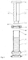
- Fig. 1
- eine Grundausführung des erfindungsgemäßen Spenders des Wirkstoffs;
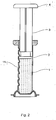
- Fig. 2
- eine Ausführung des Spenders des Wirkstoffs nach
Fig. 1 mit den Rastmitteln auf der Innenseite des Grundkörpers des Spenders; - Fig. 3
- eine Ausführung des Spenders des Wirkstoffs nach
Fig. 1 mit den Rastmitteln auf der Kolbenstange; und - Fig. 4
- eine explodierte Darstellung der Ausführung nach
Fig. 3 . - Fig. 5
- eine perspektivische Abbildung der zweiten Ausführungsform des Spenders
- Fig. 6
- eine Einzelndarstellung der Manschette aus
Fig. 5 . - Die Grundausführung des erfindungsgemäßen Spenders des Wirkstoffs, die in
Fig. 1 veranschaulicht ist, besteht aus einem Grundkörper 1, der eine Form eines Hohlzylinders mit kreisrundem Durchschnitt aufweist, obwohl auch andere Durchschnitte des Grundkörpers, beispielsweise ein sechskantiger Durchschnitt, denkbar sind. In den Grundkörper 1 ist dichtend ein Kolben 2 mit einer entsprechenden Außenkontur eingeschoben, also mit einem kreisrunden Umfang, wenn kreisrund auch der innere Durchschnitt des Grundkörpers ist. Dieser Kolben 2 ist starr mit einer Kolbenstange 3 verbunden, beziehungsweise einteilig mit dieser Kolbenstange 3 ausgebildet, die in sämtlichen Stellungen des Kolbens 2 innerhalb des Grundkörpers 1 aus diesem Grundkörper 1 axial herausragt und auf ihrem freien Ende mit einer Druckplatte 4 versehen ist. - Innerhalb des Grundkörpers 1 ist unter dem Kolben 2 ein Wirkstoff 5 in der Form von Gel, Paste oder in einer anderen passenden dickflüssigen Form angeordnet. Auf dem unteren Ende des Grundkörpers 1 dem Kolben 2 gegenüber ist eine Ausgabeöffnung 6 für den Wirkstoff 5 ausgebildet, der mittels eines Kragens 7 erweitert werden kann, der beispielsweise mittels eines aufsetzbaren Deckels 8 verschlossen werden kann, wenn der Wirkstoff 5 in dem Grundkörper 1 unter dem Kolben 2 zurückgehalten werden soll, bzw. wenn der Wirkstoff 5 gegen Austrocknen geschützt werden soll oder ein ungewolltes Ausdrücken des Wirkstoffs 5 aus dem Grundkörper verhindert werden soll.
- Die bereits erwähnte Kolbenstange 3 braucht nicht mehr den vollen Durchschnitt wie der Kolben 2 einnehmen, vielmehr reicht es, wenn diese Kolbenstange 3 in dem Grundkörper 1 mittels der Längsrippen 31 geführt wird, die auf den Innenumfang des Grundkörpers 1 auf zumindest drei Stellen anliegen, wobei aus Herstellungsgründen vier solche Stellen bevorzugt sind. Der Grundkörper 1 ist des Weiteren auf seinem der Ausgabeöffnung 6 gegenüberliegenden Ende mit einer Manschette 9 in der Form von einem Telleransatz oder einem Paar von Fingerstützen versehen, die
Fig. 1 nach einteilig mit dem Grundkörper 1 oderFig. 3 und4 nach separat ausgebildet werden kann und in diesem Fall mit dem Grundkörper 1 mittels einer Gewindeverbindung verbunden ist, die aus einem Außengewinde 101 auf dem Grundkörper 1 und einem entsprechenden Innengewinde 102 in der Manschette 9 besteht. - Die abgewandelte Ausführung, die in
Fig. 5 abgebildet ist, weist einen nicht dargestellten Kolben mit einer zylinderförmigen Kolbenstange 3 auf, in der die Rastmittel als Vertiefungen oder Öffnungen 32 vorgesehen sind, die mit der Raste 91 zusammenwirken, die auf der Manschette 9 ausgebildet ist. Die Auflaufkanten 33 und 94 der Vertiefungen oder Öffnungen 32 und der Raste 91 (sieheFig. 6 ) können in Abhängigkeit von der bestrebten Wirkungsweise dieser Rastmittel symmetrisch oder asymmetrisch geformt werden. - Die Funktionsweise des derart beschriebenen Spenders des Wirkstoffs ist im Einklang mit
Fig. 1 , wie folgt: - Durch Drücken auf den Kolben 2, also auf seine Druckplatte 4 in Richtung zu der Ausgabeöffnung 6 wird auf eine nicht gezeigte Unterlage, beispielsweise auf die innere Wand eines Klosettbeckens, durch die Ausgabeöffnung 6 eine erforderliche Menge des Wirkstoffs 5 herausdrückt, der sich anschließend in dem Spülwasser u.ä. auflöst. Es kann sich aber auch um einen Wirkstoff 5 handeln, der trocken bleibt und sich in die Umgebungsluft verdampfen oder sublimieren wird, bzw. auf diese Weise sein wirksamer Bestandteil verdampfen oder sublimieren wird.
- Die beschriebene Lösung weist den bisher benutzten Ausgabebehältern, Käfigen und ähnlich gegenüber den Vorteil auf, dass das Material gespart wird und auch die Gefahr der Kontaminierung dieser Ausgabebehälter, Käfige und ähnlich durch Verunreinigungen und Bakterien ausgeschlossen ist, die sich hier sogar vermehren könnten.
- In dem Ausführungsbeispiel des Spenders des Wirkstoffes 5 nach
Fig. 2 ist zusätzlich zu dem Ausführungsbeispiel nachFig. 1 auch die Reproduzierbarkeit der Dosierung des Wirkstoffs 5 während seiner Auftragung auf die nicht gezeigte Unterlage gelöst. Diese Aufgabe wird mittels der Rastmittel 11, beispielsweise Vorsprünge in der Form von Sägezähnen gelöst, die hintereinander in der Längsrichtung des Grundkörpers 1 auf der Innenwand dieses Grundkörpers 1 angeordnet sind. Der Kolben 2 muss bei seiner Bewegung zu der Ausgabeöffnung 6 diese Rastmittel 11 überwinden und wird also in definierten Stellungen angehalten, sodass auch aus der Ausgabeöffnung 6 jeweils eine definierte Menge von Wirkstoff 5 ausgegeben wird. - In dem Ausführungsbeispiel des Spenders des Wirkstoffs 5 nach
Fig. 3 wird die Reproduzierbarkeit der Dosierung des Wirkstoffs 5 während seiner Auftragung auf die nicht gezeigte Unterlage im Gegenteil zu der Ausführung nachFig. 2 dadurch gelöst, dass die Rastmittel 11 in der Form von Kerben im Gegenteil auf der Kolbenstange 3, insbesondere auf der Kante einer deren Längsrippen 31, wobei diese Rastmittel mit einer Raste 91 zusammenwirken, die auf dem Grundkörper 1, beispielsweise auf seiner Manschette 9 ausgebildet ist. - In
Fig. 4 ist schließlich zwecks einer besseren Anschaulichkeit eine explodierte Darstellung des Spenders des Wirkstoffes 5 nachFig. 3 abgebildet, wobei aus dieser Darstellung die Anordnung der einzelnen Bestandteile des Spenders gegenseitig entnehmbar ist. - In Bezug auf die Rastmittel 11 in den Ausführungen nach
Fig. 2 bis 4 ist noch darauf zu verweisen, dass diese einbahnig funktionieren können, d.h. dass sie infolge ihrer asymmetrischen Form eine sprunghafte Bewegung des Kolbens 2 nur in Richtung zu der Ausgabeöffnung 6 gestatten können, wenn mit einer wiederholten Füllung des Grundkörpers 1 mit dem Wirkstoff 5 nicht gerechnet wird. - Zwecks Kontrolle des Inhalts des Wirkstoffs 5 in dem Grundkörper 1 ist allgemein von Vorteil, wenn der Grundkörper 1 aus einem transparenten oder lichtdurchlässigen Material gefertigt ist, zum Beispiel aus einem passenden Kunststoff, aus dem auch alle anderen Teile des Spenders hergestellt werden können.
-
- 1
- Grundköper
- 2
- Kolben
- 3
- Kolbenstange
- 31
- Längsrippe
- 32
- Öffnung
- 33
- Auflaufkante
- 4
- Druckplatte
- 5
- Wirkstoff
- 6
- Ausgabeöffnung
- 7
- Kragen
- 8
- Deckel
- 9
- Manschette
- 91
- Raste
- 94
- Auflaufkante.
- 101
- Außengewinde
- 102
- Innengewinde
- 11
- Rastmittel
Claims (14)
- Spender eines Wirkstoffs, der aus einem Grundkörper (1) in der Form eines Hohlzylinders besteht, in dem dichtend verschiebbar ein Kolben (2) gelagert ist, dem gegenüber in dem Grundkörperende eine Ausgabeöffnung (6) ausgebildet ist, zwischen der und dem Kolben (2) sich in dem Grundkörper (1) der Wirkstoff (5) befindet, dadurch gekennzeichnet, dass an den Kolben (2) auf seiner von der Ausgabeöffnung (6) abgewandten Seite eine Kolbenstange (3) anschließt, die mit zumindest einem ihren Teil aus dem Grundkörper (1) vorsteht und unmittelbar nur mit ihrem Umfang verschiebbar in dem Grundkörper (1) gelagert ist.
- Spender nach Anspruch 1, dadurch gekennzeichnet, dass die Kolbenstange (3) in dem Grundkörper (1) unmittelbar durch die äußeren Kanten ihrer Längsrippen (31) gelagert ist.
- Spender nach Anspruch 1 oder 2, dadurch gekennzeichnet, dass die Kolbenstange (3) auf ihrem von dem Kolben (2) abgewandten Ende außerhalb des Grundkörpers (1) eine Druckplatte (4) aufweist.
- Spender nach einem der Ansprüche 1 bis 3, dadurch gekennzeichnet, dass der Grundkörper (1) auf seinem Ende der Ausgabeöffnung (6) ringsumher mit einem Kragen (7) versehen ist.
- Spender nach Anspruch 4, dadurch gekennzeichnet, dass der Kragen (7) auf dem Grundkörper (1) mittels eines abnehmbaren Deckels (8) verschlossen ist.
- Spender nach einem der Ansprüche 1 bis 5, dadurch gekennzeichnet, dass der Grundkörper (1) und/oder die Kolbenstange (3) mit Rastmitteln (11) versehen ist.
- Spender nach Anspruch 6, dadurch gekennzeichnet, dass die Rastmittel (11) als Vorsprünge in der Form von Sägezähnen ausgebildet sind, die hintereinander in der Längsrichtung des Grundkörpers (1) auf der inneren Wand dieses Grundkörpers (1) angeordnet sind.
- Spender nach Anspruch 6, dadurch gekennzeichnet, dass die Rastmittel (11) als Vorsprünge in der Form von Sägezähnen ausgebildet sind, die hintereinander in der Längsrichtung der Kolbenstange (3) auf der äußeren Seite dieser Kolbenstange (3) der Raste (91) auf dem Grundkörper (1) gegenüber angeordnet sind.
- Spender nach Anspruch 6, dadurch gekennzeichnet, dass die Rastmittel (11) als Vertiefungen oder Öffnungen (32) ausgebildet sind, die hintereinander in Längsrichtung der Kolbenstange (3) auf der äußeren Seite dieser Kolbenstange (3) gegen die Raste (91) auf der inneren Seite der Manschette (9) auf dem Grundkörper (1) angeordnet sind.
- Spender nach Anspruch 9, dadurch gekennzeichnet, dass die Vertiefungen oder Öffnungen (32) eine rechteckige Form mit Auflaufkanten (33) für die Raste (91) aufweisen, die auch mit entsprechenden Auflaufkanten (94) versehen ist.
- Spender nach Anspruch 10, dadurch gekennzeichnet, dass die Auflaufkanten (33, 94) der Vertiefungen oder Öffnungen (32) und der Raste (91) für die beiden Bewegungsrichtungen der Kolbenstange (2) symmetrisch abgeschränkt sind.
- Spender nach Anspruch 10, dadurch gekennzeichnet, dass die Auflaufkanten (33, 94) der Vertiefungen oder Öffnungen (32) und der Raste (91) für die einzelnen Bewegungsrichtungen der Kolbenstange (2) asymmetrisch abgeschränkt sind.
- Spender nach einem der Ansprüche 1 bis 8, dadurch gekennzeichnet, dass der Grundkörper (1) auf dem von der Ausgabeöffnung (6) abgewandten Ende mit einer radial abstehenden Manschette (9) versehen ist.
- Spender nach einem der Ansprüche 1 bis 13, dadurch gekennzeichnet, dass der Grundkörper (1) aus einem transparenten und/oder lichtdurchlässigen Material besteht.
Priority Applications (1)
| Application Number | Priority Date | Filing Date | Title |
|---|---|---|---|
| PL11001075T PL2363354T3 (pl) | 2010-02-10 | 2011-02-10 | Dozownik substancji czynnej |
Applications Claiming Priority (2)
| Application Number | Priority Date | Filing Date | Title |
|---|---|---|---|
| CZ20100105A CZ2010105A3 (cs) | 2010-02-10 | 2010-02-10 | Dispensor úcinné látky |
| CZ20100188A CZ2010188A3 (cs) | 2010-03-15 | 2010-03-15 | Dispensor úcinné látky |
Publications (2)
| Publication Number | Publication Date |
|---|---|
| EP2363354A1 true EP2363354A1 (de) | 2011-09-07 |
| EP2363354B1 EP2363354B1 (de) | 2012-12-19 |
Family
ID=44212268
Family Applications (1)
| Application Number | Title | Priority Date | Filing Date |
|---|---|---|---|
| EP11001075A Not-in-force EP2363354B1 (de) | 2010-02-10 | 2011-02-10 | Spender eines Wirkstoffs |
Country Status (5)
| Country | Link |
|---|---|
| EP (1) | EP2363354B1 (de) |
| DE (1) | DE202011109852U1 (de) |
| ES (1) | ES2401586T3 (de) |
| PL (1) | PL2363354T3 (de) |
| PT (1) | PT2363354E (de) |
Cited By (2)
| Publication number | Priority date | Publication date | Assignee | Title |
|---|---|---|---|---|
| EP3871999A4 (de) * | 2019-06-14 | 2022-08-03 | JMC Administração E Participações LTDA | Vorrichtung zum auftragen von selbstklebenden hygieneprodukten |
| US12546101B2 (en) | 2020-11-12 | 2026-02-10 | S. C. Johnson & Son, Inc. | System and methods for storing and dispensing a flowable material |
Citations (5)
| Publication number | Priority date | Publication date | Assignee | Title |
|---|---|---|---|---|
| FR1200293A (fr) * | 1958-03-27 | 1959-12-21 | Distributeur doseur | |
| WO1988006568A1 (en) * | 1987-03-04 | 1988-09-07 | Package Research Corporation | Toothpaste dispenser |
| DE29718910U1 (de) * | 1997-10-23 | 1997-12-11 | Rudolf Futterer Inhaber Maria Müller, 68723 Schwetzingen | Behälter für Getränke |
| US20070007302A1 (en) * | 2005-07-08 | 2007-01-11 | Doraiswami Jaichandra | Device for dispensing a controlled dose of a flowable material |
| US20070051750A1 (en) * | 2005-09-03 | 2007-03-08 | Kettenbach Gmbh & Co. Kg | Cartridge |
-
2011
- 2011-02-10 PT PT110010758T patent/PT2363354E/pt unknown
- 2011-02-10 PL PL11001075T patent/PL2363354T3/pl unknown
- 2011-02-10 DE DE202011109852U patent/DE202011109852U1/de not_active Expired - Lifetime
- 2011-02-10 EP EP11001075A patent/EP2363354B1/de not_active Not-in-force
- 2011-02-10 ES ES11001075T patent/ES2401586T3/es active Active
Patent Citations (6)
| Publication number | Priority date | Publication date | Assignee | Title |
|---|---|---|---|---|
| FR1200293A (fr) * | 1958-03-27 | 1959-12-21 | Distributeur doseur | |
| WO1988006568A1 (en) * | 1987-03-04 | 1988-09-07 | Package Research Corporation | Toothpaste dispenser |
| DE29718910U1 (de) * | 1997-10-23 | 1997-12-11 | Rudolf Futterer Inhaber Maria Müller, 68723 Schwetzingen | Behälter für Getränke |
| US20070007302A1 (en) * | 2005-07-08 | 2007-01-11 | Doraiswami Jaichandra | Device for dispensing a controlled dose of a flowable material |
| WO2007008531A1 (en) | 2005-07-08 | 2007-01-18 | S. C. Johnson & Son, Inc. | Device for dispensing a controlled dose of a flowable material |
| US20070051750A1 (en) * | 2005-09-03 | 2007-03-08 | Kettenbach Gmbh & Co. Kg | Cartridge |
Cited By (2)
| Publication number | Priority date | Publication date | Assignee | Title |
|---|---|---|---|---|
| EP3871999A4 (de) * | 2019-06-14 | 2022-08-03 | JMC Administração E Participações LTDA | Vorrichtung zum auftragen von selbstklebenden hygieneprodukten |
| US12546101B2 (en) | 2020-11-12 | 2026-02-10 | S. C. Johnson & Son, Inc. | System and methods for storing and dispensing a flowable material |
Also Published As
| Publication number | Publication date |
|---|---|
| EP2363354B1 (de) | 2012-12-19 |
| PT2363354E (pt) | 2013-03-18 |
| DE202011109852U1 (de) | 2012-06-15 |
| ES2401586T3 (es) | 2013-04-22 |
| PL2363354T3 (pl) | 2013-05-31 |
Similar Documents
| Publication | Publication Date | Title |
|---|---|---|
| DE69808559T2 (de) | Behälter für zur Benutzung aufzulösende Pulver oder Flüssigkeiten | |
| DE3339180C2 (de) | Austragvorrichtung für Medien | |
| EP2425896B1 (de) | Spritze für den Gebrauch mit einer Dosiervorrichtung | |
| EP1986789B1 (de) | Dosiervorrichtung mit einer manuell betätigbaren pumpeinrichtung | |
| DE3239784A1 (de) | Doppelbehaelter fuer zwei getrennt aufzubewahrende fluessigkeiten | |
| DE29506682U1 (de) | Abgabepumpe aus Kunststoff für pastenartige Stoffe | |
| EP0923993A1 (de) | Spender für fliessfähige Medien | |
| EP2200752A1 (de) | Dosierungsvorrichtung | |
| DE102016207722A1 (de) | Flüssigkeitsspender | |
| EP0053329A1 (de) | Spendebehälter zur portionsweisen Abgabe eines pastösen Gutes | |
| DE2644786C3 (de) | Ausgabedüse, insbesondere für flüssige und halbflüssige Substanzen | |
| DE60304577T2 (de) | Spritzenanordnung | |
| EP0103110A2 (de) | Beimischgerät | |
| DE102013202933B3 (de) | Kindergesicherte Austragvorrichtung | |
| WO2010072575A2 (de) | Dosiervorrichtung zur erzeugung eines gasstromes mit einem in diesem fein verteilten wirkstoff | |
| DE2248891B2 (de) | Schieberkolben für ein hydraulisches Mehrwegeventil | |
| EP2363354B1 (de) | Spender eines Wirkstoffs | |
| DE3122031C2 (de) | ||
| EP2158136B1 (de) | Vorrichtung zum austragen einer fliessfähigen substanz | |
| DE102007021454B4 (de) | Spender für Flüssigkeiten | |
| EP0388651B1 (de) | Austragvorrichtung für Medien | |
| WO2008113611A1 (de) | Verfahren und vorrichtung zum dosierten ausbringen eines mediums | |
| DE102013114336A1 (de) | Dosierung entnehmbar | |
| DE202011103529U1 (de) | Verschluss- und Haltevorrichtung für ein Behältnis, insbesondere Tube | |
| DE3328553C2 (de) |
Legal Events
| Date | Code | Title | Description |
|---|---|---|---|
| PUAI | Public reference made under article 153(3) epc to a published international application that has entered the european phase |
Free format text: ORIGINAL CODE: 0009012 |
|
| 17P | Request for examination filed |
Effective date: 20110602 |
|
| AK | Designated contracting states |
Kind code of ref document: A1 Designated state(s): AL AT BE BG CH CY CZ DE DK EE ES FI FR GB GR HR HU IE IS IT LI LT LU LV MC MK MT NL NO PL PT RO RS SE SI SK SM TR |
|
| AX | Request for extension of the european patent |
Extension state: BA ME |
|
| PUAJ | Public notification under rule 129 epc |
Free format text: ORIGINAL CODE: 0009425 |
|
| 32PN | Public notification |
Free format text: MITTEILUNG GEMAESS REGEL 59 UND REGEL 163(2)EPU (EPA FORM 1111VOM 25/10/2011) |
|
| GRAP | Despatch of communication of intention to grant a patent |
Free format text: ORIGINAL CODE: EPIDOSNIGR1 |
|
| GRAS | Grant fee paid |
Free format text: ORIGINAL CODE: EPIDOSNIGR3 |
|
| GRAA | (expected) grant |
Free format text: ORIGINAL CODE: 0009210 |
|
| AK | Designated contracting states |
Kind code of ref document: B1 Designated state(s): AL AT BE BG CH CY CZ DE DK EE ES FI FR GB GR HR HU IE IS IT LI LT LU LV MC MK MT NL NO PL PT RO RS SE SI SK SM TR |
|
| REG | Reference to a national code |
Ref country code: GB Ref legal event code: FG4D Free format text: NOT ENGLISH |
|
| REG | Reference to a national code |
Ref country code: CH Ref legal event code: EP |
|
| REG | Reference to a national code |
Ref country code: AT Ref legal event code: REF Ref document number: 589273 Country of ref document: AT Kind code of ref document: T Effective date: 20130115 |
|
| REG | Reference to a national code |
Ref country code: DE Ref legal event code: R096 Ref document number: 502011000282 Country of ref document: DE Effective date: 20130207 |
|
| REG | Reference to a national code |
Ref country code: RO Ref legal event code: EPE |
|
| REG | Reference to a national code |
Ref country code: PT Ref legal event code: SC4A Free format text: AVAILABILITY OF NATIONAL TRANSLATION Effective date: 20130312 |
|
| REG | Reference to a national code |
Ref country code: NL Ref legal event code: T3 |
|
| REG | Reference to a national code |
Ref country code: ES Ref legal event code: FG2A Ref document number: 2401586 Country of ref document: ES Kind code of ref document: T3 Effective date: 20130422 |
|
| PG25 | Lapsed in a contracting state [announced via postgrant information from national office to epo] |
Ref country code: NO Free format text: LAPSE BECAUSE OF FAILURE TO SUBMIT A TRANSLATION OF THE DESCRIPTION OR TO PAY THE FEE WITHIN THE PRESCRIBED TIME-LIMIT Effective date: 20130319 Ref country code: SE Free format text: LAPSE BECAUSE OF FAILURE TO SUBMIT A TRANSLATION OF THE DESCRIPTION OR TO PAY THE FEE WITHIN THE PRESCRIBED TIME-LIMIT Effective date: 20121219 Ref country code: HR Free format text: LAPSE BECAUSE OF FAILURE TO SUBMIT A TRANSLATION OF THE DESCRIPTION OR TO PAY THE FEE WITHIN THE PRESCRIBED TIME-LIMIT Effective date: 20121219 Ref country code: FI Free format text: LAPSE BECAUSE OF FAILURE TO SUBMIT A TRANSLATION OF THE DESCRIPTION OR TO PAY THE FEE WITHIN THE PRESCRIBED TIME-LIMIT Effective date: 20121219 Ref country code: LT Free format text: LAPSE BECAUSE OF FAILURE TO SUBMIT A TRANSLATION OF THE DESCRIPTION OR TO PAY THE FEE WITHIN THE PRESCRIBED TIME-LIMIT Effective date: 20121219 |
|
| REG | Reference to a national code |
Ref country code: SK Ref legal event code: T3 Ref document number: E 13515 Country of ref document: SK |
|
| REG | Reference to a national code |
Ref country code: LT Ref legal event code: MG4D |
|
| PG25 | Lapsed in a contracting state [announced via postgrant information from national office to epo] |
Ref country code: GR Free format text: LAPSE BECAUSE OF FAILURE TO SUBMIT A TRANSLATION OF THE DESCRIPTION OR TO PAY THE FEE WITHIN THE PRESCRIBED TIME-LIMIT Effective date: 20130320 Ref country code: SI Free format text: LAPSE BECAUSE OF FAILURE TO SUBMIT A TRANSLATION OF THE DESCRIPTION OR TO PAY THE FEE WITHIN THE PRESCRIBED TIME-LIMIT Effective date: 20121219 Ref country code: LV Free format text: LAPSE BECAUSE OF FAILURE TO SUBMIT A TRANSLATION OF THE DESCRIPTION OR TO PAY THE FEE WITHIN THE PRESCRIBED TIME-LIMIT Effective date: 20121219 |
|
| REG | Reference to a national code |
Ref country code: PL Ref legal event code: T3 |
|
| PG25 | Lapsed in a contracting state [announced via postgrant information from national office to epo] |
Ref country code: IS Free format text: LAPSE BECAUSE OF FAILURE TO SUBMIT A TRANSLATION OF THE DESCRIPTION OR TO PAY THE FEE WITHIN THE PRESCRIBED TIME-LIMIT Effective date: 20130419 Ref country code: RS Free format text: LAPSE BECAUSE OF FAILURE TO SUBMIT A TRANSLATION OF THE DESCRIPTION OR TO PAY THE FEE WITHIN THE PRESCRIBED TIME-LIMIT Effective date: 20121219 Ref country code: EE Free format text: LAPSE BECAUSE OF FAILURE TO SUBMIT A TRANSLATION OF THE DESCRIPTION OR TO PAY THE FEE WITHIN THE PRESCRIBED TIME-LIMIT Effective date: 20121219 |
|
| PG25 | Lapsed in a contracting state [announced via postgrant information from national office to epo] |
Ref country code: MC Free format text: LAPSE BECAUSE OF NON-PAYMENT OF DUE FEES Effective date: 20130228 |
|
| PLBE | No opposition filed within time limit |
Free format text: ORIGINAL CODE: 0009261 |
|
| STAA | Information on the status of an ep patent application or granted ep patent |
Free format text: STATUS: NO OPPOSITION FILED WITHIN TIME LIMIT |
|
| PG25 | Lapsed in a contracting state [announced via postgrant information from national office to epo] |
Ref country code: DK Free format text: LAPSE BECAUSE OF FAILURE TO SUBMIT A TRANSLATION OF THE DESCRIPTION OR TO PAY THE FEE WITHIN THE PRESCRIBED TIME-LIMIT Effective date: 20121219 |
|
| 26N | No opposition filed |
Effective date: 20130920 |
|
| REG | Reference to a national code |
Ref country code: HU Ref legal event code: AG4A Ref document number: E017327 Country of ref document: HU |
|
| PG25 | Lapsed in a contracting state [announced via postgrant information from national office to epo] |
Ref country code: CY Free format text: LAPSE BECAUSE OF FAILURE TO SUBMIT A TRANSLATION OF THE DESCRIPTION OR TO PAY THE FEE WITHIN THE PRESCRIBED TIME-LIMIT Effective date: 20121219 |
|
| REG | Reference to a national code |
Ref country code: IE Ref legal event code: MM4A |
|
| REG | Reference to a national code |
Ref country code: DE Ref legal event code: R097 Ref document number: 502011000282 Country of ref document: DE Effective date: 20130920 |
|
| PG25 | Lapsed in a contracting state [announced via postgrant information from national office to epo] |
Ref country code: IE Free format text: LAPSE BECAUSE OF NON-PAYMENT OF DUE FEES Effective date: 20130210 Ref country code: AL Free format text: LAPSE BECAUSE OF FAILURE TO SUBMIT A TRANSLATION OF THE DESCRIPTION OR TO PAY THE FEE WITHIN THE PRESCRIBED TIME-LIMIT Effective date: 20121219 |
|
| PGFP | Annual fee paid to national office [announced via postgrant information from national office to epo] |
Ref country code: RO Payment date: 20140210 Year of fee payment: 4 |
|
| PGFP | Annual fee paid to national office [announced via postgrant information from national office to epo] |
Ref country code: TR Payment date: 20140204 Year of fee payment: 4 Ref country code: HU Payment date: 20140228 Year of fee payment: 4 |
|
| PG25 | Lapsed in a contracting state [announced via postgrant information from national office to epo] |
Ref country code: MT Free format text: LAPSE BECAUSE OF FAILURE TO SUBMIT A TRANSLATION OF THE DESCRIPTION OR TO PAY THE FEE WITHIN THE PRESCRIBED TIME-LIMIT Effective date: 20121219 |
|
| REG | Reference to a national code |
Ref country code: CH Ref legal event code: PL |
|
| PG25 | Lapsed in a contracting state [announced via postgrant information from national office to epo] |
Ref country code: LI Free format text: LAPSE BECAUSE OF NON-PAYMENT OF DUE FEES Effective date: 20140228 Ref country code: CH Free format text: LAPSE BECAUSE OF NON-PAYMENT OF DUE FEES Effective date: 20140228 |
|
| PG25 | Lapsed in a contracting state [announced via postgrant information from national office to epo] |
Ref country code: SM Free format text: LAPSE BECAUSE OF FAILURE TO SUBMIT A TRANSLATION OF THE DESCRIPTION OR TO PAY THE FEE WITHIN THE PRESCRIBED TIME-LIMIT Effective date: 20121219 |
|
| PG25 | Lapsed in a contracting state [announced via postgrant information from national office to epo] |
Ref country code: MK Free format text: LAPSE BECAUSE OF FAILURE TO SUBMIT A TRANSLATION OF THE DESCRIPTION OR TO PAY THE FEE WITHIN THE PRESCRIBED TIME-LIMIT Effective date: 20121219 Ref country code: LU Free format text: LAPSE BECAUSE OF NON-PAYMENT OF DUE FEES Effective date: 20130210 |
|
| PG25 | Lapsed in a contracting state [announced via postgrant information from national office to epo] |
Ref country code: RO Free format text: LAPSE BECAUSE OF NON-PAYMENT OF DUE FEES Effective date: 20150210 |
|
| PG25 | Lapsed in a contracting state [announced via postgrant information from national office to epo] |
Ref country code: HU Free format text: LAPSE BECAUSE OF NON-PAYMENT OF DUE FEES Effective date: 20150211 |
|
| REG | Reference to a national code |
Ref country code: FR Ref legal event code: PLFP Year of fee payment: 6 |
|
| PGFP | Annual fee paid to national office [announced via postgrant information from national office to epo] |
Ref country code: BG Payment date: 20160226 Year of fee payment: 6 |
|
| REG | Reference to a national code |
Ref country code: FR Ref legal event code: PLFP Year of fee payment: 7 |
|
| PG25 | Lapsed in a contracting state [announced via postgrant information from national office to epo] |
Ref country code: TR Free format text: LAPSE BECAUSE OF NON-PAYMENT OF DUE FEES Effective date: 20150210 |
|
| REG | Reference to a national code |
Ref country code: FR Ref legal event code: PLFP Year of fee payment: 8 |
|
| PGFP | Annual fee paid to national office [announced via postgrant information from national office to epo] |
Ref country code: NL Payment date: 20180214 Year of fee payment: 8 |
|
| PGFP | Annual fee paid to national office [announced via postgrant information from national office to epo] |
Ref country code: GB Payment date: 20180214 Year of fee payment: 8 Ref country code: ES Payment date: 20180327 Year of fee payment: 8 |
|
| PGFP | Annual fee paid to national office [announced via postgrant information from national office to epo] |
Ref country code: SK Payment date: 20180131 Year of fee payment: 8 Ref country code: PT Payment date: 20180201 Year of fee payment: 8 Ref country code: FR Payment date: 20180228 Year of fee payment: 8 Ref country code: BE Payment date: 20180227 Year of fee payment: 8 Ref country code: AT Payment date: 20180220 Year of fee payment: 8 |
|
| PG25 | Lapsed in a contracting state [announced via postgrant information from national office to epo] |
Ref country code: BG Free format text: LAPSE BECAUSE OF NON-PAYMENT OF DUE FEES Effective date: 20170903 |
|
| PGFP | Annual fee paid to national office [announced via postgrant information from national office to epo] |
Ref country code: PL Payment date: 20190131 Year of fee payment: 9 Ref country code: DE Payment date: 20190211 Year of fee payment: 9 Ref country code: CZ Payment date: 20190114 Year of fee payment: 9 Ref country code: IT Payment date: 20190208 Year of fee payment: 9 |
|
| REG | Reference to a national code |
Ref country code: NL Ref legal event code: MM Effective date: 20190301 |
|
| REG | Reference to a national code |
Ref country code: AT Ref legal event code: MM01 Ref document number: 589273 Country of ref document: AT Kind code of ref document: T Effective date: 20190210 |
|
| GBPC | Gb: european patent ceased through non-payment of renewal fee |
Effective date: 20190210 |
|
| PG25 | Lapsed in a contracting state [announced via postgrant information from national office to epo] |
Ref country code: SK Free format text: LAPSE BECAUSE OF NON-PAYMENT OF DUE FEES Effective date: 20190210 Ref country code: PT Free format text: LAPSE BECAUSE OF NON-PAYMENT OF DUE FEES Effective date: 20190812 |
|
| REG | Reference to a national code |
Ref country code: SK Ref legal event code: MM4A Ref document number: E 13515 Country of ref document: SK Effective date: 20190210 |
|
| REG | Reference to a national code |
Ref country code: BE Ref legal event code: MM Effective date: 20190228 |
|
| PG25 | Lapsed in a contracting state [announced via postgrant information from national office to epo] |
Ref country code: AT Free format text: LAPSE BECAUSE OF NON-PAYMENT OF DUE FEES Effective date: 20190210 |
|
| PG25 | Lapsed in a contracting state [announced via postgrant information from national office to epo] |
Ref country code: GB Free format text: LAPSE BECAUSE OF NON-PAYMENT OF DUE FEES Effective date: 20190210 Ref country code: NL Free format text: LAPSE BECAUSE OF NON-PAYMENT OF DUE FEES Effective date: 20190301 |
|
| PG25 | Lapsed in a contracting state [announced via postgrant information from national office to epo] |
Ref country code: FR Free format text: LAPSE BECAUSE OF NON-PAYMENT OF DUE FEES Effective date: 20190228 Ref country code: BE Free format text: LAPSE BECAUSE OF NON-PAYMENT OF DUE FEES Effective date: 20190228 |
|
| REG | Reference to a national code |
Ref country code: ES Ref legal event code: FD2A Effective date: 20200330 |
|
| PG25 | Lapsed in a contracting state [announced via postgrant information from national office to epo] |
Ref country code: ES Free format text: LAPSE BECAUSE OF NON-PAYMENT OF DUE FEES Effective date: 20190211 |
|
| REG | Reference to a national code |
Ref country code: DE Ref legal event code: R119 Ref document number: 502011000282 Country of ref document: DE |
|
| PG25 | Lapsed in a contracting state [announced via postgrant information from national office to epo] |
Ref country code: CZ Free format text: LAPSE BECAUSE OF NON-PAYMENT OF DUE FEES Effective date: 20200210 |
|
| PG25 | Lapsed in a contracting state [announced via postgrant information from national office to epo] |
Ref country code: DE Free format text: LAPSE BECAUSE OF NON-PAYMENT OF DUE FEES Effective date: 20200901 |
|
| PG25 | Lapsed in a contracting state [announced via postgrant information from national office to epo] |
Ref country code: PL Free format text: LAPSE BECAUSE OF NON-PAYMENT OF DUE FEES Effective date: 20200210 |
|
| PG25 | Lapsed in a contracting state [announced via postgrant information from national office to epo] |
Ref country code: IT Free format text: LAPSE BECAUSE OF NON-PAYMENT OF DUE FEES Effective date: 20200210 |