EP2363367A2 - Machine textile et raccord de tuyau - Google Patents
Machine textile et raccord de tuyau Download PDFInfo
- Publication number
- EP2363367A2 EP2363367A2 EP20110155566 EP11155566A EP2363367A2 EP 2363367 A2 EP2363367 A2 EP 2363367A2 EP 20110155566 EP20110155566 EP 20110155566 EP 11155566 A EP11155566 A EP 11155566A EP 2363367 A2 EP2363367 A2 EP 2363367A2
- Authority
- EP
- European Patent Office
- Prior art keywords
- pipes
- pipe joint
- sealing member
- peripheral surface
- yarn
- Prior art date
- Legal status (The legal status is an assumption and is not a legal conclusion. Google has not performed a legal analysis and makes no representation as to the accuracy of the status listed.)
- Withdrawn
Links
- 239000004753 textile Substances 0.000 title claims description 20
- 238000005192 partition Methods 0.000 claims abstract description 84
- 238000004891 communication Methods 0.000 claims abstract description 35
- 238000007789 sealing Methods 0.000 claims description 68
- 230000002093 peripheral effect Effects 0.000 claims description 27
- 239000012530 fluid Substances 0.000 claims description 8
- 239000013013 elastic material Substances 0.000 claims description 6
- 238000000034 method Methods 0.000 claims description 6
- 239000002994 raw material Substances 0.000 claims description 6
- 230000008569 process Effects 0.000 claims description 4
- 238000009987 spinning Methods 0.000 claims description 4
- 238000004804 winding Methods 0.000 description 26
- 239000007789 gas Substances 0.000 description 20
- 239000002184 metal Substances 0.000 description 13
- 230000007547 defect Effects 0.000 description 4
- 238000012986 modification Methods 0.000 description 4
- 230000004048 modification Effects 0.000 description 4
- 230000008859 change Effects 0.000 description 2
- 230000009467 reduction Effects 0.000 description 2
- 229920002943 EPDM rubber Polymers 0.000 description 1
- 238000005452 bending Methods 0.000 description 1
- 239000003086 colorant Substances 0.000 description 1
- 230000004069 differentiation Effects 0.000 description 1
- 229920001971 elastomer Polymers 0.000 description 1
- HQQADJVZYDDRJT-UHFFFAOYSA-N ethene;prop-1-ene Chemical group C=C.CC=C HQQADJVZYDDRJT-UHFFFAOYSA-N 0.000 description 1
- 239000000835 fiber Substances 0.000 description 1
- 229910001220 stainless steel Inorganic materials 0.000 description 1
- 239000010935 stainless steel Substances 0.000 description 1
- 229920001897 terpolymer Polymers 0.000 description 1
Images


Classifications
-
- F—MECHANICAL ENGINEERING; LIGHTING; HEATING; WEAPONS; BLASTING
- F16—ENGINEERING ELEMENTS AND UNITS; GENERAL MEASURES FOR PRODUCING AND MAINTAINING EFFECTIVE FUNCTIONING OF MACHINES OR INSTALLATIONS; THERMAL INSULATION IN GENERAL
- F16L—PIPES; JOINTS OR FITTINGS FOR PIPES; SUPPORTS FOR PIPES, CABLES OR PROTECTIVE TUBING; MEANS FOR THERMAL INSULATION IN GENERAL
- F16L29/00—Joints with fluid cut-off means
-
- B—PERFORMING OPERATIONS; TRANSPORTING
- B65—CONVEYING; PACKING; STORING; HANDLING THIN OR FILAMENTARY MATERIAL
- B65H—HANDLING THIN OR FILAMENTARY MATERIAL, e.g. SHEETS, WEBS, CABLES
- B65H54/00—Winding, coiling, or depositing filamentary material
- B65H54/70—Other constructional features of yarn-winding machines
-
- B—PERFORMING OPERATIONS; TRANSPORTING
- B65—CONVEYING; PACKING; STORING; HANDLING THIN OR FILAMENTARY MATERIAL
- B65H—HANDLING THIN OR FILAMENTARY MATERIAL, e.g. SHEETS, WEBS, CABLES
- B65H69/00—Methods of, or devices for, interconnecting successive lengths of material; Knot-tying devices ;Control of the correct working of the interconnecting device
- B65H69/06—Methods of, or devices for, interconnecting successive lengths of material; Knot-tying devices ;Control of the correct working of the interconnecting device by splicing
- B65H69/061—Methods of, or devices for, interconnecting successive lengths of material; Knot-tying devices ;Control of the correct working of the interconnecting device by splicing using pneumatic means
-
- F—MECHANICAL ENGINEERING; LIGHTING; HEATING; WEAPONS; BLASTING
- F16—ENGINEERING ELEMENTS AND UNITS; GENERAL MEASURES FOR PRODUCING AND MAINTAINING EFFECTIVE FUNCTIONING OF MACHINES OR INSTALLATIONS; THERMAL INSULATION IN GENERAL
- F16L—PIPES; JOINTS OR FITTINGS FOR PIPES; SUPPORTS FOR PIPES, CABLES OR PROTECTIVE TUBING; MEANS FOR THERMAL INSULATION IN GENERAL
- F16L17/00—Joints with packing adapted to sealing by fluid pressure
- F16L17/02—Joints with packing adapted to sealing by fluid pressure with sealing rings arranged between outer surface of pipe and inner surface of sleeve or socket
- F16L17/04—Joints with packing adapted to sealing by fluid pressure with sealing rings arranged between outer surface of pipe and inner surface of sleeve or socket with longitudinally split or divided sleeve
-
- F—MECHANICAL ENGINEERING; LIGHTING; HEATING; WEAPONS; BLASTING
- F16—ENGINEERING ELEMENTS AND UNITS; GENERAL MEASURES FOR PRODUCING AND MAINTAINING EFFECTIVE FUNCTIONING OF MACHINES OR INSTALLATIONS; THERMAL INSULATION IN GENERAL
- F16L—PIPES; JOINTS OR FITTINGS FOR PIPES; SUPPORTS FOR PIPES, CABLES OR PROTECTIVE TUBING; MEANS FOR THERMAL INSULATION IN GENERAL
- F16L21/00—Joints with sleeve or socket
- F16L21/06—Joints with sleeve or socket with a divided sleeve or ring clamping around the pipe ends
- F16L21/065—Joints with sleeve or socket with a divided sleeve or ring clamping around the pipe ends tightened by tangentially-arranged threaded pins
-
- F—MECHANICAL ENGINEERING; LIGHTING; HEATING; WEAPONS; BLASTING
- F16—ENGINEERING ELEMENTS AND UNITS; GENERAL MEASURES FOR PRODUCING AND MAINTAINING EFFECTIVE FUNCTIONING OF MACHINES OR INSTALLATIONS; THERMAL INSULATION IN GENERAL
- F16L—PIPES; JOINTS OR FITTINGS FOR PIPES; SUPPORTS FOR PIPES, CABLES OR PROTECTIVE TUBING; MEANS FOR THERMAL INSULATION IN GENERAL
- F16L21/00—Joints with sleeve or socket
- F16L21/08—Joints with sleeve or socket with additional locking means
-
- B—PERFORMING OPERATIONS; TRANSPORTING
- B65—CONVEYING; PACKING; STORING; HANDLING THIN OR FILAMENTARY MATERIAL
- B65H—HANDLING THIN OR FILAMENTARY MATERIAL, e.g. SHEETS, WEBS, CABLES
- B65H2701/00—Handled material; Storage means
- B65H2701/30—Handled filamentary material
- B65H2701/31—Textiles threads or artificial strands of filaments
Definitions
- the present invention relates to textile machines and pipe joints.
- a technique for joining two pipes together with a pipe joint in a manner that allows communication between the two pipes is known in the art (see, for example, Japanese published unexamined application No. 2000-170971 ). Gases having the same pressure are typically supplied into the two pipes joined together with such a pipe joint. If gases having different pressures are to be supplied into the two pipes, or a gas having a predetermined pressure is to be supplied into only one of the pipes, the pipe joint is removed and lids are attached to open end portions of the pipes to seal the end portions.
- a textile machine includes a plurality of processing units each of which includes an operation device that processes any one of a textile raw material and a yarn formed by spinning the textile raw material; a pipe joint; and two pipes configured to be joined together with the pipe joint.
- a first operation device being one or a plurality of the operation devices, is coupled to a first pipe, being one of the two pipes.
- a second operation device being one or a plurality of the operation devices, is coupled to a second pipe, being the other one of the two pipes.
- a partition member that selectively opens and shuts off a gas communication between the two pipes is detachably mounted in the pipe joint.
- a pipe joint for joining two pipes together to allow a fluid to flow through the two pipes includes a sealing member, which is made of an elastic material, that comes into close contact with outer peripheral surfaces of end portions, at which the two pipes are joined together, of the two pipes to prevent leakage of the fluid from the two pipes; a clamping member that clamps the sealing member; and a partition member that is detachably mounted in the sealing member.
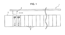
- FIG. 1 is an elevation view illustrating a schematic configuration of an automatic winder 1 according to an embodiment of the present invention.
- FIG. 2 is an elevation view of a winding unit 2 of the automatic winder 1.
- the automatic winder 1 includes a plurality of winding units 2 (processing units) arranged in a row, a doffer 3 movable in a direction along which the winding units 2 are arranged, and a machine frame 4 that includes a control unit that performs an overall control of the automatic winder 1.
- the automatic winder 1 is configured such that each of the winding units 2 winds a spun yarn Y unwound from a yarn feeding bobbin B on a winding tube 11 to form a package P.
- the doffer 3 moves to a position above the corresponding winding unit 2, removes the package P, and mounts an empty winding tube 11, i.e., a winding tube 11 on which no yarn has been wound, in place of the package P.
- the configuration of the winding unit 2 is described in detail below.
- the winding unit 2 illustrated in FIG. 2 forms the fully wound package P by winding the spun yarn Y unwound from the yarn feeding bobbin B on the winding tube 11 while causing the spun yarn Y to traverse.
- the winding unit 2 includes, at its top portion, a cradle 12 provided on a unit frame (not shown) that rotatably holds the winding tube 11 and, at its bottom portion, a traversing drum 13 that is also rotatably supported by the unit frame.
- the traversing drum 13 is rotated by a drum driving motor 28.
- a helical traversing groove 13a that causes the spun yarn Y to traverse is formed on the surface of the traversing drum 13. While causing the spun yarn Y to traverse along the traversing groove 13a, the traversing drum 13 is rotated in a state of being in contact with the package P formed by winding the spun yarn Y on the winding tube 11. As a result, the package P is rotated by frictional contact between the package P and the traversing drum 13 causing the spun yarn Y unwound from the yarn feeding bobbin B to be wound on the winding tube 11.
- an unwinding assisting device 17 As illustrated in FIG. 2 , on a yarn path from the yarn feeding bobbin B to the traversing drum 13, an unwinding assisting device 17, a yarn-breakage detecting unit 18, a tensioning device 19, a splicer device 20 (operation device), and a clearer (yarn defect clean up device) 21 are arranged in this order.
- the unwinding assisting device 17 includes a cylindrical member 25 arranged over the yarn feeding bobbin B and a driving device 26 that causes the cylindrical member 25 to descend.
- the driving device 26 is controlled such that a clearance between the cylindrical member 25 and a leading end (chase portion) of a yarn layer of the yarn feeding bobbin B is maintained substantially constant so that the yarn Y is unwound stably.
- the yarn-breakage detecting unit 18 determines presence/absence of the spun yarn Y in a portion between the unwinding assisting device 17 and the tensioning device 19.
- the tensioning device 19 applies a predetermined tension to the running spun yarn Y.
- a tensioning device of a gate type having fixed teeth 19a and movable teeth 19b is employed as the tensioning device 19.
- the tensioning device 19 is pivotable to place the teeth 19a in a state meshed with the teeth 19b or in a state released from the teeth 19b.
- the tensioning device 19 is caused to pivot by a rotary solenoid 27.
- the splicer device 20 splices a lower yarn Y1 on the yarn feeding bobbin B to an upper yarn Y2 on the package P when, for example, yarn breakage occurs during unwinding or when a yarn is cut, to remove a yarn defect detected by the clearer 21.
- the clearer 21 will be described later.
- the splicer device 20 is an operation device that is operated with a compressed air and that is generally known as an air splicer.
- the air splicer supplies the compressed air into a space where the lower yarn Y1 and the upper yarn Y2 overlaid on each other are housed so that an air flow generated in the space intertwines the lower yarn Y1 and the upper yarn Y2 with each other, thereby achieving splicing.
- Air splicers are known in the art, see for example Japanese published unexamined application No. S61-257877 , so that detail description about the air splicer is omitted herefrom.
- a lower-yarn catching-and-guiding member 22 and an upper-yarn catching-and-guiding member 23 are provided above the splicer device 20 and below the splicer device 20, respectively.
- the lower-yarn catching-and-guiding member 22 catches the lower yarn Y1 extending from the yarn feeding bobbin B and guides the yarn to the splicer device 20.
- the upper-yarn catching-and-guiding member 23 catches the upper yarn Y2 extending from the package P and guides the yarn to the splicer device 20.
- a suction mouth 22a in the lower-yarn catching-and-guiding member 22 catches a yarn end of the lower yarn Y1 at the position illustrated in FIG. 2 .
- the lower-yarn catching-and-guiding member 22 then pivots upward to guide the lower yarn Y1 to the splicer device 20.
- a suction mouth 23a of the upper-yarn catching-and-guiding member 23 pivots from the position illustrated in FIG. 2 to a yarn-end catching position near a contact point between the package P and the traversing drum 13.
- the upper-yarn catching-and-guiding member 23 catches a yarn end of the upper yarn Y2 extending from the package P. Thereafter, the suction mouth 23a pivots downward again, thereby guiding the upper yarn Y2 to the splicer device 20.
- the clearer 21 detects a yarn defect, such as a slub, formed in the spun yarn Y.
- a cutter 21a used for cutting a yarn when a yarn defect is detected is annexed to the clearer 21.
- a structure that supplies the compressed air to the splicer device 20 is described below.
- a structure that simultaneously supplies the compressed air to the splicer devices 20 of two winding units 2 is described below.
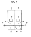
- the splicer devices 20 of the two winding units 2 are individually coupled to two pressure pipes 32 via inlet pipes 34 in a one-to-one relationship. First ends of the two pressure pipes 32 are joined together with a pipe joint 40. Second ends of the pressure pipes 32 are coupled to a pump 30 (air-pressure adjusting devices), respectively.
- the pipe joint 40 that joins the two pressure pipes 32 together includes, in its interior, a partition plate (partition member) 51 that blocks a communication between the two pressure pipes 32.
- the partition plate 51 will be described later.
- the pipe joint 40 includes a cylindrical clamping collar 41 with a slit 41a, a metal plate 45 in contact with an inner peripheral surface of the clamping collar 41, a cylindrical sealing member 50 in contact with an inner peripheral surface of the metal plate 45, and the partition plate 51 that divides an interior space of the sealing member 50 into two.
- the clamping collar 41 is made of a metal such as Japanese Industrial Standards (JIS) SUS304 (stainless steel).
- JIS Japanese Industrial Standards
- the metal plate 45 is a thin metal plate rolled into a cylindrical shape.
- the sealing member 50 is a member made of an elastic material such as rubber.
- Two clamping plates 42 made of a metal, such as JIS SUS304, and facing each other are joined to the clamping collar 41 individually at two edges, with the slit 41a therebetween, of the clamping collar 41.
- Each of the clamping plates 42 is tangential to the clamping collar 41 at a corresponding one of the edges.
- the free end of the clamping plate 42 is curved to form a hollow cylinder.
- a shaft 43 is arranged inside this hollow cylinder.
- Two through holes are formed in the shafts 43 such that the through holes are positioned at different positions on an axis of the shafts 43 and radially pass through the shaft 43. Openings are formed in the clamping plates 42 at positions corresponding to the through holes to allow the through holes in the shafts 43 to be exposed.
- Two bolts 44 are inserted through the through holes in a first shaft 43, being one of the shafts 43, in the cylinder formed by one of the two clamping plates 42 with leading ends of the two bolts 44 screwed in the through holes, which are threaded, in a second shaft 43, being the other of the shafts 43. Fastening of the bolts 44 leads to a movement of the shafts 43 toward each other. Accordingly, the clamping plates 42 are also moved toward each other leading to a reduction in the diameter of the clamping collar 41.
- the clamping plates 42, the shafts 43, and the bolts 44 of the present embodiment are an example of a clamping member in the present invention.
- the metal plate 45 is a thin plate rolled into a cylindrical shape.
- the metal plate 45 includes bent portions 45a formed by inwardly bending two end portions, which are on axially opposite ends, of the metal plate 45.
- a toothed member 45c in which a plurality of notches 45b spaced from each other are defined along the periphery, is attached to each of the bent portions 45a.
- the sealing member 50 includes two annular protrusions 50a spaced from each other in the axial direction of the sealing member 50 and projecting from an inner peripheral surface of an axial center portion of the sealing member 50.
- a mounting portion 50c in which the disc-shaped partition plate 51 made of a metal can be detachably mounted, is provided between the two protrusions 50a of the sealing member 50.
- the mounting portion 50c is an annular recess defined between the two protrusions 50d.
- the outer diameter of the partition plate 51 is slightly greater than the inner diameter of the sealing member 50 at a position where the annular recess between the two protrusions 50a is located. This arrangement causes the partition plate 51 to be press-fit into the annular recess between the two protrusions 50a.
- the sealing member should preferably be made of ethylenepropylene terpolymer (EPDM).
- Sealing protrusions 50b projecting radially inward are formed on the inner peripheral surface of axial two end portions of the sealing member 50.
- the partition plate 51 in the sealing member 50 fits in the annular recess between the two protrusions 50a and pressed by the sealing member 50. This advantageously shuts off the communication between the two pressure pipes 32 more reliably because the partition plate 51 is prevented from moving and the partition plate 51 is caught between the two protrusions 50a, causing the gap between the sealing member 50 and the partition plate 51 to be sealed tightly.
- the toothed member 45c having the notches 45b and attached to the metal plate 45 prevents the pressure pipes 32 from sliding off the pipe joint 40.
- loosening of the bolts 44 leads to an increase in the diameter of the clamping collar 41, which in turn increases the diameter of the metal plate 45, loosening clamping effected by the sealing member 50.
- the partition plate 51 can be removed from inside the sealing member 50.
- the pumps 30 serving as the air-pressure adjusting devices are individually coupled to the two pressure pipes 32 as illustrated in FIG. 3 . Therefore, it is possible to cause the two pressure pipes 32 to have different internal pressures by operating the two pumps 30 such that the pumps 30 deliver different pressures.
- the splicer devices 20 individually coupled to the pressure pipes 32 via the inlet pipes 34 are supplied with the compressed airs having the different pressures. Accordingly, air flows that differ from each other in a rotary torque from one splicer device to other splicer device can be created in the splicer devices 20.
- winding units 2 including the splicer devices 20 wind spun yarns Y of different yarn types, or, more specifically, of different yarn thicknesses, fibers intertwine with one another in different manners that depend on a relationship between the yarn type and the rotary torque of the air flow.
- a first pump 30 delivers a pressure of 0.4 megapascals (MPa) while the other one of the pumps 30 (hereinafter, “a second pump 30”) delivers a pressure of 0.8 MPa
- a pressure difference as great as 0.4 MPa can develop between one of the pressure pipes 32 (hereinafter, "a first pressure pipe 32") coupled to the first pump 30 and the other one of the pressure pipes 32 (hereinafter, “a second pressure pipe 32") coupled to the second pump 30.
- a first pressure pipe 32 coupled to the first pump 30
- a second pressure pipe 32 coupled to the second pump 30.
- the valve may not shut off the communication sufficiently, resulting in occurrence of a leakage.
- the configuration that includes a valve is not only complicated in structure but also expensive.
- the communication between the two pressure pipes 32 individually coupled to the two splicer devices 20 can be shut off reliably. Accordingly, it is possible to supply the compressed airs having different pressures, each of which is optimum for a corresponding one of the splicer devices 20, to each of the splicer device 20, corresponding to a first operation device, coupled to the first pressure pipe 32 and the splicer device 20, corresponding to a second operation device, coupled to the second pressure pipe 32.
- the partition plate 51 can be demounted from the mounting portion 50c so that the two pressure pipes 32 are joined together with a pipe joint 140, in which the partition plate 51 is not mounted.
- the pipe joint 140 is similar to the pipe joint 40 in structure except that the partition plate 51 is not mounted in the pipe joint 140.
- Differentiation between the pipe joint 40, in which the partition plate 51 is mounted on the mounting portion 50c, and the pipe joint 140, in which the partition plate 51 is not mounted can be made by using different colors for the bolts 44 of the pipe joint 40 and those for the pipe joint 140 or by applying a marking to an externally easy-to-see position. This allows, even in a state where the two pressure pipes 32 are joined together with a pipe joint, determination as to whether the pipe joint is the pipe joint 40, in which the partition plate 51 is mounted, or the pipe joint 140, in which the partition plate 51 is not mounted, to be made easily without disassembling the pipe joint to determine whether the pipe joint includes the partition plate 51.
- a recess 46 (identifier portion) is provided in the clamping plate 42 of only the pipe joint 40, in which the partition plate 51 is mounted. Meanwhile, any one of an arrangement where such an identifier portion is provided on either one of the pipe joint 40 and the pipe joint 140, and an arrangement where different identifier portions are individually provided on the pipe joint 40 and the pipe joint 140 can be employed so long as determination as to whether the pipe joint includes the partition plate 51 can be made based on the identifier portion(s).
- the pipe joint 40 has such a simple structure that the partition plate 51 is mounted in the sealing member 50, the pipe joint 40 can shut off the communication between the two pressure pipes 32 reliably. Accordingly, the communication between the two pressure pipes 32 in a state where the two pressure pipes 32 are joined together can be shut off only by mounting the partition plate 51 to the pipe joint 140, in which the partition plate 51 is not mounted, by using the pipe joint 40 that is identical in the configuration with the pipe joint 140 except that the pipe joint 40 includes the partition plate 51.
- the communication between the two pressure pipes 32 has been shut off by attaching lids to the open end portions of the two pressure pipes 32 to seal the end portions.
- the pipe joint 40 in which the partition plate 51 is mounted, can be easily mounted only by deforming the sealing member 50, which is an elastic member, so that the pipe joint 40 caps the end portions of the pressure pipe 32 without changing the lengths of the pressure pipes 32 or the clearance between the pressure pipes 32.
- the two pressure pipes 32 joined together with the pipe joint 40 have been coupled to the splicer devices 20 each being an air splicer; alternatively, other types of operation devices can be coupled to the two pressure pipes 32 so long as such operation devices are operated with a compressed gas or a depressurized gas supplied via the two pressure pipes 32.
- the suction mouth 23a and the like that, when a yarn breakage occurs or when a yarn is cut, sucks and catches a yarn end and conveys the yarn end to the splicer can be coupled to the pressure pipes 32.
- the different pumps 30 are individually coupled to the two pressure pipes 32; alternatively, an arrangement where only one of the pumps 30 is coupled to one of the pressure pipes 32 (hereinafter, “pump-coupled pressure pipe 32") and the other one of the pumps 30 is not coupled to the other pressure pipe 32 (hereinafter, “pump not-coupled pressure pipe 32”) can be employed.
- pump-coupled pressure pipe 32 an arrangement where only one of the pumps 30 is coupled to one of the pressure pipes 32
- pump not-coupled pressure pipe 32 an arrangement where only one of the pumps 30 is coupled to one of the pressure pipes 32
- pump not-coupled pressure pipe 32 an arrangement where only one of the pumps 30 is coupled to one of the pressure pipes 32
- pump not-coupled pressure pipe 32 an arrangement where only one of the pumps 30 is coupled to one of the pressure pipes 32
- pump not-coupled pressure pipe 32 an arrangement where only one of the pumps 30 is coupled to one of the pressure pipes 32
- pump not-coupled pressure pipe 32 an arrangement where only one of the pumps 30 is coupled to one of the pressure pipes 32
- the two protrusions 50a where the partition plate 51 is positioned are formed on the sealing member 50; however, the two protrusions 50a may not be provided.
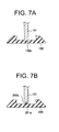
- the partition plate 51 is located in the annular recess between the two protrusions 50a formed on the sealing member 50 to seal the gap between the sealing member 50 and the partition plate 51 tightly; alternatively, as illustrated in FIG. 7A , a configuration where an annular recess 150a is defined in a sealing member 150 and the partition plate 51 is located in the recess 150a can be employed. Furthermore, a configuration illustrated in FIG. 7B where a recess 251a and a protrusion 250a that can engage with each other are provided on a partition plate 251 and a sealing member 250, respectively, can be employed.
- the pipe joint 40 of the present invention is applied to the automatic winder 1; however, an intended object to which the pipe joint of the invention is applied is not limited to the automatic winder 1.
- the pipe joint can be applied not only to various textile machines, such as spinning machines, but also to apparatuses other than the textile machines, so long as the machine includes a structure for opening and shutting off a communication between two pipes.
- a textile machine includes a plurality of processing units each of which includes an operation device that processes any one of a textile raw material and a yarn formed by spinning the textile raw material; a pipe joint; and two pipes configured to be joined together with the pipe joint.
- a first operation device being one or a plurality of the operation devices, is coupled to a first pipe, being one of the two pipes.
- a second operation device being one or a plurality of the operation devices, is coupled to a second pipe, being the other one of the two pipes.
- a partition member that selectively opens and shuts off a gas communication between the two pipes is detachably mounted in the pipe joint.
- the pipe joint allows, by using the single pipe joint, the gas communication between the two pipes to be selectively opened and shut off only by mounting and demounting the partition member in and from the pipe joint. Furthermore, it is not necessary to adjust the clearance between the pipes when opening or shutting off the gas communication between the two pipes because it is possible to selectively open and shut off the gas communication by using the single pipe joint.
- the first pipe is preferably coupled to a first air-pressure adjusting device that generates a compressed gas or a depressurized gas that operates the first operation device.
- the second pipe is preferably coupled to a second air-pressure adjusting device that generates a compressed gas or a depressurized gas that operates the second operation device.
- the pipe joint in which the partition member is mounted, preferably shuts off the gas communication between the two pipes. This arrangement allows different pressures to be developed in the two pipes even when the two pipes are joined together, thereby making it possible to operate the first operation device and the second operation device with the gases having different pressures.
- the pipe joint preferably includes a sealing member, which has a cylindrical shape and which is made of an elastic material, that comes into close contact with outer peripheral surfaces of end portions, at which the two pipes are joined together, of the two pipes to prevent leakage of the gas from the two pipes; and a clamping member that clamps the sealing member in a manner that reduces a diameter of the sealing member.
- the partition member is preferably formed into a disc shape.
- a mounting portion, with which an outer peripheral surface of the partition member is brought into close contact to mount the partition member therein, is preferably provided on an inner peripheral surface of an axial center portion of the sealing member. With this arrangement, the partition member mounted in the mounting portion seals a gap between the sealing member and the partition member tightly, thereby shutting off the communication between the two pipes reliably.
- the mounting portion should preferably be an annular recess formed in the inner peripheral surface of the axial center portion of the sealing member. This arrangement prevents the outer peripheral surface of the partition member from fitting in the recess in the sealing member, thereby preventing movement of the partition member so that the communication between the two pipes can be shut off more reliably. This arrangement also facilitates mounting and demounting of the partition member.
- annular recess should preferably be provided between two annular protrusions that are spaced from each other in an axial direction of the sealing member and provided on the inner peripheral surface of the axial center portion of the sealing member. This arrangement shuts off the communication between the two pipes more reliably because movement of the partition member is prevented and the partition member is caught between the two protrusions, causing the gap between the sealing member and the partition member to be sealed tightly.
- the operation devices should preferably be splicer devices that splice yarns by using an air flow.
- This arrangement allows, by selectively opening and shutting off the communication between the two pipes, operations of a plurality of the splicer devices to be effected at a single pressure or different pressures. Accordingly, even when yarns of different yarn types that differ from one another in necessary pressure to be delivered to a splicer device are to be processed by the processing units, it is possible to operate the splicer devices at different pressures, each depending on the yarn type.
- a pipe joint for joining two pipes together to allow a fluid to flow through the two pipes includes a sealing member, which is made of an elastic material, that comes into close contact with outer peripheral surfaces of end portions, at which the two pipes are joined together, of the two pipes to prevent leakage of the fluid from the two pipes; a clamping member that clamps the sealing member; and a partition member that is detachably mounted in the sealing member.
- the pipe joint allows, by using the single pipe joint, fluid communication between the two pipes to be selectively opened and shut off only by mounting and demounting the partition member in and from the pipe joint.
- the sealing member should preferably be formed into a cylindrical shape.
- the partition member should preferably be formed into a disc shape.
- a mounting portion, with which an outer peripheral surface of the partition member is brought into close contact to mount the partition member therein, should preferably be provided on an inner peripheral surface of an axial center portion of the sealing member.
- the mounting portion should preferably be an annular recess formed in the inner peripheral surface of the axial center portion of the sealing member. This arrangement prevents the outer peripheral surface of the partition member from fitting in the recess in the sealing member, thereby preventing movement of the partition member so that the communication between the two pipes can be shut off more reliably.
- annular recess should preferably be provided between two annular protrusions that are spaced from each other in an axial direction of the sealing member and provided on the inner peripheral surface of the axial center portion of the sealing member. This arrangement shuts off the communication between the two pipes more reliably because movement of the partition member is prevented and the partition member is caught between the two protrusions, causing the gap between the sealing member and the partition member to be sealed tightly.
Landscapes
- Engineering & Computer Science (AREA)
- General Engineering & Computer Science (AREA)
- Mechanical Engineering (AREA)
- Physics & Mathematics (AREA)
- Fluid Mechanics (AREA)
- Textile Engineering (AREA)
- Spinning Or Twisting Of Yarns (AREA)
- Joints With Sleeves (AREA)
- Joints That Cut Off Fluids, And Hose Joints (AREA)
Applications Claiming Priority (1)
| Application Number | Priority Date | Filing Date | Title |
|---|---|---|---|
| JP2010045104A JP2011179140A (ja) | 2010-03-02 | 2010-03-02 | 繊維機械及び管継ぎ手 |
Publications (1)
| Publication Number | Publication Date |
|---|---|
| EP2363367A2 true EP2363367A2 (fr) | 2011-09-07 |
Family
ID=44087656
Family Applications (1)
| Application Number | Title | Priority Date | Filing Date |
|---|---|---|---|
| EP20110155566 Withdrawn EP2363367A2 (fr) | 2010-03-02 | 2011-02-23 | Machine textile et raccord de tuyau |
Country Status (3)
| Country | Link |
|---|---|
| EP (1) | EP2363367A2 (fr) |
| JP (1) | JP2011179140A (fr) |
| CN (2) | CN102191595A (fr) |
Cited By (2)
| Publication number | Priority date | Publication date | Assignee | Title |
|---|---|---|---|---|
| US20170074433A1 (en) * | 2012-01-20 | 2017-03-16 | Mueller International, Llc | Coupling gasket with multiple sealing surfaces |
| US10385997B2 (en) | 2012-01-20 | 2019-08-20 | Anvil International, Llc | Slip-on coupling gasket |
Families Citing this family (5)
| Publication number | Priority date | Publication date | Assignee | Title |
|---|---|---|---|---|
| CN107246393A (zh) * | 2017-07-31 | 2017-10-13 | 广东美芝制冷设备有限公司 | 用于压缩机的连接管组件以及压缩机 |
| CN108657803B (zh) * | 2018-07-02 | 2023-12-12 | 浙江凯成智能设备股份有限公司 | 一种喇叭管自动下管及送入总成 |
| JP7393214B2 (ja) * | 2020-01-15 | 2023-12-06 | ショーボンドマテリアル株式会社 | 管継手の締付確認用スペーサ |
| CN116676693A (zh) * | 2023-06-14 | 2023-09-01 | 常州市宏发纵横新材料科技股份有限公司 | 一种纤维空捻装置及拼接方法 |
| DE102023121236A1 (de) * | 2023-08-09 | 2025-02-13 | Viega Technology Gmbh & Co. Kg | Rohrverbinder zum dichten verbinden zweier rohrenden, verwendung desselben und verfahren |
Citations (2)
| Publication number | Priority date | Publication date | Assignee | Title |
|---|---|---|---|---|
| JPS61257877A (ja) | 1985-04-12 | 1986-11-15 | Murata Mach Ltd | 糸継ノズルユニツト |
| JP2000170971A (ja) | 1998-12-09 | 2000-06-23 | Sho Bond Constr Co Ltd | 管継手 |
-
2010
- 2010-03-02 JP JP2010045104A patent/JP2011179140A/ja active Pending
-
2011
- 2011-02-23 EP EP20110155566 patent/EP2363367A2/fr not_active Withdrawn
- 2011-03-02 CN CN 201110050008 patent/CN102191595A/zh active Pending
- 2011-03-02 CN CN 201120052797 patent/CN202023020U/zh not_active Expired - Fee Related
Patent Citations (2)
| Publication number | Priority date | Publication date | Assignee | Title |
|---|---|---|---|---|
| JPS61257877A (ja) | 1985-04-12 | 1986-11-15 | Murata Mach Ltd | 糸継ノズルユニツト |
| JP2000170971A (ja) | 1998-12-09 | 2000-06-23 | Sho Bond Constr Co Ltd | 管継手 |
Cited By (5)
| Publication number | Priority date | Publication date | Assignee | Title |
|---|---|---|---|---|
| US20170074433A1 (en) * | 2012-01-20 | 2017-03-16 | Mueller International, Llc | Coupling gasket with multiple sealing surfaces |
| US10385997B2 (en) | 2012-01-20 | 2019-08-20 | Anvil International, Llc | Slip-on coupling gasket |
| US10641421B2 (en) * | 2012-01-20 | 2020-05-05 | Anvil International, Llc | Coupling gasket with multiple sealing surfaces |
| US11365835B2 (en) | 2012-01-20 | 2022-06-21 | ASC Engineered Solutions, LLC | Coupling gasket with multiple sealing surfaces |
| US11739869B2 (en) | 2012-01-20 | 2023-08-29 | ASC Engineered Solutions, LLC | Coupling gasket with multiple sealing surfaces |
Also Published As
| Publication number | Publication date |
|---|---|
| CN102191595A (zh) | 2011-09-21 |
| CN202023020U (zh) | 2011-11-02 |
| JP2011179140A (ja) | 2011-09-15 |
Similar Documents
| Publication | Publication Date | Title |
|---|---|---|
| EP2363367A2 (fr) | Machine textile et raccord de tuyau | |
| EP2511214B1 (fr) | Dispositif de bobinage de fil et enrouleur automatique | |
| EP1916213B1 (fr) | Fileuse dotée d'un dispositif d'élimination du relâchement des fils | |
| JP5001849B2 (ja) | 綾巻きパッケージを製造する繊維機械の作業箇所を運転するための方法および装置 | |
| CN106995952B (zh) | 用于在转杯纺纱机的转杯纺纱装置处准备用来接头的纱线端部的方法以及转杯纺纱机 | |
| EP1717182B1 (fr) | Dispositif d'élimination des relâchements de fil dans une machine textile | |
| EP3865441B1 (fr) | Bobineuse de fil | |
| US7770373B2 (en) | Core fiber detecting method and device in core yarn spinning | |
| CN102574655B (zh) | 纱线卷绕装置 | |
| JP2005112632A (ja) | 巻き取り装置 | |
| JP5804306B2 (ja) | 糸貯留装置及び糸巻取機 | |
| EP2977493B1 (fr) | Métier à filer et procédé de filage | |
| EP2966023A1 (fr) | Machine de renvideur de fil et procédé de renvidage de fil | |
| CN105883482B (zh) | 筒管支承装置以及纱线卷绕机 | |
| JP2016016958A (ja) | 糸巻取機及び糸巻取方法 | |
| CN109911710B (zh) | 用于制造交叉卷绕筒子的纺织机的工位的旋转接纱器 | |
| EP2684826A1 (fr) | Dispositif d'enroulement de fil | |
| CN107777464B (zh) | 抽吸装置和用传感器监测抽吸装置的抽吸通道部段的方法 | |
| EP2848565B1 (fr) | Machine de renvideur de fil | |
| EP2161232A2 (fr) | Freinage global et enrouleur automatique l'incluant | |
| CN1334364A (zh) | 转杯纺纱机 | |
| US6666012B2 (en) | Process and device for pneumatic retention of a yarn | |
| JP2015016989A (ja) | 綾巻きパッケージを製造する繊維機械の作業部 | |
| CN111601764B (zh) | 纱线卷取机以及纱线卷取方法 | |
| JP2009227413A (ja) | 糸巻取機 |
Legal Events
| Date | Code | Title | Description |
|---|---|---|---|
| PUAI | Public reference made under article 153(3) epc to a published international application that has entered the european phase |
Free format text: ORIGINAL CODE: 0009012 |
|
| AK | Designated contracting states |
Kind code of ref document: A2 Designated state(s): AL AT BE BG CH CY CZ DE DK EE ES FI FR GB GR HR HU IE IS IT LI LT LU LV MC MK MT NL NO PL PT RO RS SE SI SK SM TR |
|
| AX | Request for extension of the european patent |
Extension state: BA ME |
|
| STAA | Information on the status of an ep patent application or granted ep patent |
Free format text: STATUS: THE APPLICATION HAS BEEN WITHDRAWN |
|
| 18W | Application withdrawn |
Effective date: 20120119 |