EP2363369A1 - Wicklungsvorrichtung - Google Patents
Wicklungsvorrichtung Download PDFInfo
- Publication number
- EP2363369A1 EP2363369A1 EP11154602A EP11154602A EP2363369A1 EP 2363369 A1 EP2363369 A1 EP 2363369A1 EP 11154602 A EP11154602 A EP 11154602A EP 11154602 A EP11154602 A EP 11154602A EP 2363369 A1 EP2363369 A1 EP 2363369A1
- Authority
- EP
- European Patent Office
- Prior art keywords
- coil
- core
- roller
- feeding device
- retaining means
- Prior art date
- Legal status (The legal status is an assumption and is not a legal conclusion. Google has not performed a legal analysis and makes no representation as to the accuracy of the status listed.)
- Withdrawn
Links
- 238000004804 winding Methods 0.000 title description 9
- 238000013519 translation Methods 0.000 claims description 12
- RYGMFSIKBFXOCR-UHFFFAOYSA-N Copper Chemical compound [Cu] RYGMFSIKBFXOCR-UHFFFAOYSA-N 0.000 description 4
- 239000004809 Teflon Substances 0.000 description 4
- 229920006362 Teflon® Polymers 0.000 description 4
- 230000006978 adaptation Effects 0.000 description 3
- 230000005540 biological transmission Effects 0.000 description 3
- 230000000903 blocking effect Effects 0.000 description 3
- 230000006835 compression Effects 0.000 description 3
- 238000007906 compression Methods 0.000 description 3
- 239000002184 metal Substances 0.000 description 3
- 229910052751 metal Inorganic materials 0.000 description 3
- 238000012549 training Methods 0.000 description 3
- XEEYBQQBJWHFJM-UHFFFAOYSA-N Iron Chemical compound [Fe] XEEYBQQBJWHFJM-UHFFFAOYSA-N 0.000 description 2
- 238000012423 maintenance Methods 0.000 description 2
- 230000005355 Hall effect Effects 0.000 description 1
- 230000000712 assembly Effects 0.000 description 1
- 238000000429 assembly Methods 0.000 description 1
- 239000004020 conductor Substances 0.000 description 1
- 229910052802 copper Inorganic materials 0.000 description 1
- 239000010949 copper Substances 0.000 description 1
- 238000013461 design Methods 0.000 description 1
- 230000000694 effects Effects 0.000 description 1
- 230000005294 ferromagnetic effect Effects 0.000 description 1
- 238000003780 insertion Methods 0.000 description 1
- 230000037431 insertion Effects 0.000 description 1
- 230000010354 integration Effects 0.000 description 1
- 229910052742 iron Inorganic materials 0.000 description 1
- 238000004519 manufacturing process Methods 0.000 description 1
- 238000000034 method Methods 0.000 description 1
- 238000003801 milling Methods 0.000 description 1
- 239000004033 plastic Substances 0.000 description 1
- 230000003449 preventive effect Effects 0.000 description 1
- 238000011084 recovery Methods 0.000 description 1
Images


Classifications
-
- H—ELECTRICITY
- H01—ELECTRIC ELEMENTS
- H01F—MAGNETS; INDUCTANCES; TRANSFORMERS; SELECTION OF MATERIALS FOR THEIR MAGNETIC PROPERTIES
- H01F41/00—Apparatus or processes specially adapted for manufacturing or assembling magnets, inductances or transformers; Apparatus or processes specially adapted for manufacturing materials characterised by their magnetic properties
- H01F41/02—Apparatus or processes specially adapted for manufacturing or assembling magnets, inductances or transformers; Apparatus or processes specially adapted for manufacturing materials characterised by their magnetic properties for manufacturing cores, coils, or magnets
- H01F41/04—Apparatus or processes specially adapted for manufacturing or assembling magnets, inductances or transformers; Apparatus or processes specially adapted for manufacturing materials characterised by their magnetic properties for manufacturing cores, coils, or magnets for manufacturing coils
- H01F41/06—Coil winding
- H01F41/08—Winding conductors onto closed formers or cores, e.g. threading conductors through toroidal cores
-
- B—PERFORMING OPERATIONS; TRANSPORTING
- B65—CONVEYING; PACKING; STORING; HANDLING THIN OR FILAMENTARY MATERIAL
- B65H—HANDLING THIN OR FILAMENTARY MATERIAL, e.g. SHEETS, WEBS, CABLES
- B65H54/00—Winding, coiling, or depositing filamentary material
- B65H54/02—Winding and traversing material on to reels, bobbins, tubes, or like package cores or formers
- B65H54/10—Winding and traversing material on to reels, bobbins, tubes, or like package cores or formers for making packages of specified shapes or on specified types of bobbins, tubes, cores, or formers
-
- B—PERFORMING OPERATIONS; TRANSPORTING
- B65—CONVEYING; PACKING; STORING; HANDLING THIN OR FILAMENTARY MATERIAL
- B65H—HANDLING THIN OR FILAMENTARY MATERIAL, e.g. SHEETS, WEBS, CABLES
- B65H81/00—Methods, apparatus, or devices for covering or wrapping cores by winding webs, tapes, or filamentary material, not otherwise provided for
- B65H81/02—Covering or wrapping annular or like cores forming a closed or substantially closed figure
- B65H81/04—Covering or wrapping annular or like cores forming a closed or substantially closed figure by feeding material obliquely to the axis of the core
-
- B—PERFORMING OPERATIONS; TRANSPORTING
- B65—CONVEYING; PACKING; STORING; HANDLING THIN OR FILAMENTARY MATERIAL
- B65H—HANDLING THIN OR FILAMENTARY MATERIAL, e.g. SHEETS, WEBS, CABLES
- B65H2701/00—Handled material; Storage means
- B65H2701/30—Handled filamentary material
- B65H2701/36—Wires
Definitions
- the present invention relates to a device for moving a coil core or a coil having a closed shape with an inner contour and an outer contour as well as a winding machine equipped with such a device.
- the winders are used to make coils from the winding of a conductor wire often copper and electrically isolated often by varnishing, around a ferromagnetic core including soft iron.
- the coil of the geometry of the nucleus is closed on itself thus delimiting a passage opening.
- the principle of these sensors lies in the variation of current generated by the passage of a metal bar inside the passage opening of the coil.
- the coil of these sensors has most of the time a toroidal shape to allow the passage in its opening of a round bar or a rectangular bar according to product families.
- This miniaturization requires changing the toroidal shape of the sensor coil and therefore requires a winder capable of winding a conductive wire around a core having a non-toroidal shape.
- a winder used to wind a toroidal core comprises three rollers arranged around the core of the coil and coming into contact therewith.
- At least one of these three rolls is driving and rotates the core at a constant speed to allow a shuttle passing through the core passage opening to wind the lead around the core section almost uniformly.
- This advance device is satisfactory for the manufacture of toroidal-shaped coils but is not intended to accommodate a core having another shape, in particular an oblong shape.
- This adaptation is to fix flat, according to its main plane, the core on a perforated plastic wedge at its opening to allow the passage of the shuttle.
- the wedge is then placed between the three rollers whose spacing has been modified and moved in translation by at least one of them.
- the document DE10146169A1 provides a solution for making a winding on a core having a non-toroidal shape and in particular an oblong shape.
- This solution consists in using a belt to rotate the core or the coil.
- the belt is tensioned by a set of rollers arranged judiciously so that it partially surrounds the core or the coil on its outer contour.
- the rotational movement of the core generated by the belt does not maintain a constant distance between the shuttle and the core or the coil, which can cause distensions of the wire on certain parts of the belt. the coil, especially on the curved parts of the core.
- the present invention aims to solve all or part of the disadvantages mentioned above.
- the subject of the present invention is a device for advancing the movement of a coil core or a coil having a closed form with an inner contour and an outer contour characterized in that it comprises a first and a second roller movable in rotation about a respective axis and intended to bear against one of the two contours of the core or the coil, means for rotating at least one of the rollers, first retaining means associated with the first roll, the first retaining means being subjected to first return means arranged to bring the first retaining means of the first other of the two contours of the core or the coil, and the second retaining means associated with the second roller, the second retaining means being subjected to second return means arranged to bring the second retaining means of the other of the two outline of the core or coil.
- This device also gives the core or the coil a revolution movement now at a substantially constant distance the coil or the core of the shuttle thus reducing the risk of distension of the wire on the core or the coil.
- the retaining means are rotatable about the axis of rotation of their respective roll.
- the device comprises two arms associated with each roller and each comprising a body on which are arranged the retaining means and the return means, said arms comprising means allowing the rotation of the retaining means around the axis of their respective roll.
- the retaining means are movable in translation along an axis intersecting the axis of rotation of their respective roll.
- the device comprises two arms associated with each roller and each comprising a body on which are arranged the retaining means and the return means, said arms comprising means allowing the translation of the retaining means along an axis. cutting the axis of rotation of their respective roll.
- At least one of the arms comprises guiding means.
- This arrangement makes it possible to maintain an arm so as to prevent it from getting in the way and impede the recessing of the shuttle wire during the advance of the core or the coil.
- the two arms each comprise means for adjusting the return means.
- This arrangement makes it possible to adjust the stiffness of the return means as a function of the thickness of the core section but also as a function of the number of overlaps and turns of the coil to be produced.
- the body has a surface intended to ensure a sliding contact of the first roller 4a or the second roller 4b.
- the device comprises a support wedge disposed on a fixed support and intended to ensure a sliding contact of the core or the coil.
- This arrangement makes it possible to maintain the movement of the core or the coil in the same plane perpendicular to the axis of rotation of the driving rollers.
- the drive means ensuring the rotational movement of at least one roller comprise a gimbal.
- the drive means comprise a play catch system.
- This arrangement eliminates the longitudinal play of the transmission that can be caused during its rotation and thus prevents a transmission break which would result in winding several turns at the same location of the core or the coil.
- the play catch system comprises at least one spring.
- the spring makes it possible to design an effective catch-up system at a lower cost.
- a wedge is used to enhance the drive means to facilitate their movement.
- the present invention also relates to a winder equipped with a feed device according to the invention.
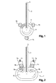
- a winder originally used to wind a core 3 or a coil 3 'of toroidal shape and subsequently adapted to accommodate a feed device 1 according to the invention, comprises a shuttle 2 passing through an opening of passage 6 of the nucleus or of the coil 3 'and delivering a copper wire 5 to wind around the core or the coil 3' and three driving rollers 4a, 4b and 4c.
- core 3 or coil 3 'to designate the part on which the coil is formed, the core 3 becoming a coil 3' after a first recovery by the copper wire 5.
- the three driving rollers 4a, 4b and 4c have a gripping surface brought into contact with the outer contour of the core 3 or the spool 3 'in order to drive the latter in rotation.
- the drive rollers 4a and 4b are arranged on either side of the shuttle 2 while the third drive roller 4c is arranged opposite the shuttle 2.
- the shuttle 5 rotates at a constant speed along with the three driving rollers 4a, 4b and 4c in order to position the turns of the same series of overlaps regularly next to each other.
- an advance movement device of a coil core 3 'or a coil 3' comprises only the drive rollers 4a and 4b disposed on either side of the shuttle 2 .
- the third roller 4c has been replaced by two arms 7a and 7b illustrated in detail in FIGS. Figures 3 and 4 .
- each arm 7a, 7b is disposed horizontally and consists of a body 9 having an oblong shape and a sliding contact surface 10 of the first roller 4a or the second roller 4b.
- a flat washer 33 visible to the figure 7 , is interposed between the sliding contact surface 10 and each of the rollers 4a, 4b.
- Each of the rollers 4a, 4b has a circumferential shoulder 30.
- Each of these arms 7a, 7b also comprises an oblong-shaped through opening 11 formed by milling in the direction of the length of the body 9 of the arm 7a, 7b also oblong shape.
- a return means 12 materialized by a compression spring 12 bearing on one of its ends on a means of adjustment 13 materialized in the form of an adjustable bolt passing through the body 9 and held by a nut.
- the length of the spring 12 and the adjustment of the adjusting means 13 show a passage 15 in the opening 11.
- This passage 15 is intended for the insertion of an axis 17 of a drive roller 4a, 4b.
- the action of the spring 12 keeps the arm 7a, 7b on the axis of the roller 4a, 4b in a plane substantially perpendicular to it.
- the spring 12 may comprise a Teflon sleeve 35 partially inserted in the spring 12 and increasing the contact surface with the axis 17 of a drive roller 4a, 4b.
- This sleeve 35 also has a wear ring function and improves the sliding of the shaft 17 of a drive roller 4a, 4b by the use of a Teflon metal contact.
- Each arm 7a, 7b also comprises a retaining means 8a, 8b extending transversely to the sliding contact surface 10 of the body 9 of the arm 7a, 7b and rotatably mounted on a bearing 14 incorporated in the body 9.
- At least one of the rollers 4a, 4b is rotated by drive means 20.
- Driving means 20 are illustrated in FIG. figure 5 .
- Driving means 20 comprise three parts A, B and C interlocking and sliding into each other.
- a first end of the part A slides in the part B and is kept at a distance from the latter by the action of a first compression spring 22 bearing on the one hand on one end of the part A and on the other part on the bottom of a cavity in the part B to guide in translation that same end of the part A.
- Part B slides in part C and is kept at a distance from it by the action of a second compression spring 23 which is supported by a part on an annular shoulder at the base of one end of the part B and secondly on the bottom of a cavity formed in a first end of the part C to translate this same end of the part B.
- Part C comprises a cardan joint 21 and a second cavity formed at its second end into which the axis 17 of a roller 4a or 4b.
- Each link formed by one end of the parts A, B, C and the end 24 of the axis 17 of a drive roller 4a, 4b and the different cavities formed in these different parts is provided at the using shape-matching devices to block the rotation between two adjacent parts and to allow sliding translation between two adjacent parts.
- These devices can indifferently be constituted by flats, grooves, keys or any other device known to those skilled in the art blocking the rotation without blocking the translation between two adjacent parts. It is also conceivable to leave free in translation only one of the links between two adjacent parts, in which case the other links can be locked in translation and in rotation by devices known to those skilled in the art such as screws on nuts or pins. Blocking in translation and in rotation of all the links is also possible.
- the second end 25 of the portion A comprises a spherical head with two branches extending transversely from this spherical head.
- the head and its two branches form a "T" -shaped end.
- This "T" shaped end 25 is intended to be inserted into one of the three engine cylinders 32 of the driving part 31 of the winder.
- the three engine cylinders 32 rotate together at the same rotational speed.
- each of the three engine cylinders 32 comprises two notches 29 diametrically opposed and open on the top of the engine cylinders 32 to accommodate the branches of the "T" formed on the end 25 of the part A.
- the spherical head of the end 25 is supported in the bottom of the engine cylinders 32. Teflon wedges 26 are arranged in this same The wedges 26 also have a function of wear shims by the use of a Teflon metal contact.
- a kinematic chain constituted by a motor, the three motor cylinders 32, the drive means 20 and the drive rollers 4a, 4b.
- the axis 17 of a drive roller 4a, 4b comprises a circumferential shoulder 34 maintained in the passage 15 formed between the return means 12 and the body 9 of the arm 7a, 7b.
- Each of the assemblies constituted by a roll 4a or 4b with its axis 17 is then engaged in a passage 18 formed in the support 16 which supports both the arm 7a, 7b, the drive means 20 and a roll of drive 4a, 4b.
- the diameter of the circumferential shoulder 34 is very slightly less than the width of the oblong opening 11 to minimize the clearance between the arms 7a, 7b and the axis 17 of each of the rollers 4a, 4b.
- the support 16 comprises a guiding means 19, a first part of which consists of a cylindrical element 19a protruding transversely from the face of the arm 7a, 7b coming against the support 16 and a second part 19b machined on the outer upper edge. support near the passage 18.
- This guide means 19 makes it possible to limit the travel in rotation and in translation of the body 9 of the arm 7a, 7b as winding progresses and thus prevents the body 9 from being in the recess region of the wire 5 of the shuttle 2.
- a support wedge 27 is arranged opposite the shuttle 2 in order to support the core 3 or the coil 3 'during its revolution movement.
- This support wedge 27 includes a retractable portion 28 so that it can adapt to the cores 3 or coils 3 'of different heights.
- the operator When using a winder equipped with a feed movement device 1 of a coil core 3 'or a coil 3', the operator first introduces the core 3 into the shuttle 2 at through its passage opening 6.
- the operator places the core 3 or the coil 3 'flat on the shoulder 30 of the two rollers 4a, 4b, between these same rollers 4a, 4b and the retaining means 8a, 8b and on the support wedge 27 with or without the retractable portion 28 according to the size of the core 3 or the coil 3 'to be wound.
- each arm 7a, 7b permanently maintain a section of the core 3 or the coil 3 'respectively against the driving roller 4a or 4b by the action of the return means 12.
- the stiffness of the spring 12 is adjustable by operating the adjustment means 13.
- the action of the return means 12 increases simultaneously with the thickness of the section of the coil 3 'in the holding areas of the arms 7a and 7b due to the overlap of several turns of the coil 3'.
- the retaining means 8a, 8b are free to rotate on their bearing 14 so that when the shuttle 2 and the drive part 31 are started simultaneously, the drive means 20 transmit a rotational movement to the driving rollers. 4a and 4b which in turn drive the core 3 or the coil 3 'in a plane revolution movement.
- This movement maintains at a substantially constant distance the core 3 or the reel 3 'of the shuttle 2.
- the winder winds the copper wire 5 around the section of the core 3 or the coil 3 'located in the axis of the shuttle 2, which has the effect of uniformly distributing the turns on the core 3 or the coil 3 '.
- the core 3 or the coil 3 ' may cause a slight rotational movement of the arms 7a or 7b around the axis of the drive rollers 4a, 4b on which they are mounted.
- the rotation of an arm 7a or 7b can be counterbalanced by the action of the operator who brings the arm 7a or 7b in alignment with the cross section of the core 3 or the coil 3 '.
Landscapes
- Engineering & Computer Science (AREA)
- Power Engineering (AREA)
- Manufacturing & Machinery (AREA)
- Manufacture Of Motors, Generators (AREA)
- Winding Of Webs (AREA)
Applications Claiming Priority (1)
| Application Number | Priority Date | Filing Date | Title |
|---|---|---|---|
| FR1051519A FR2957206B1 (fr) | 2010-03-03 | 2010-03-03 | Dispositif de bobinage |
Publications (1)
| Publication Number | Publication Date |
|---|---|
| EP2363369A1 true EP2363369A1 (de) | 2011-09-07 |
Family
ID=42837724
Family Applications (1)
| Application Number | Title | Priority Date | Filing Date |
|---|---|---|---|
| EP11154602A Withdrawn EP2363369A1 (de) | 2010-03-03 | 2011-02-16 | Wicklungsvorrichtung |
Country Status (5)
| Country | Link |
|---|---|
| US (1) | US20110215186A1 (de) |
| EP (1) | EP2363369A1 (de) |
| KR (1) | KR20110100166A (de) |
| CN (1) | CN102208283B (de) |
| FR (1) | FR2957206B1 (de) |
Families Citing this family (2)
| Publication number | Priority date | Publication date | Assignee | Title |
|---|---|---|---|---|
| CN104016198A (zh) * | 2014-06-12 | 2014-09-03 | 尚勤贵 | 一种线圈包带机的带轮 |
| KR102245466B1 (ko) | 2020-12-16 | 2021-04-28 | 안형준 | 사각코어용 권취장치 |
Citations (5)
| Publication number | Priority date | Publication date | Assignee | Title |
|---|---|---|---|---|
| JPS5385397U (de) * | 1976-12-14 | 1978-07-14 | ||
| FR2471034A1 (fr) * | 1979-12-04 | 1981-06-12 | Merlin Gerin | Capteur d'intensite a support souple deformable et son procede de fabrication |
| JPS6071473A (ja) * | 1983-09-26 | 1985-04-23 | Mitsubishi Electric Corp | リングワインデイング装置 |
| JPS60118580A (ja) * | 1983-11-28 | 1985-06-26 | Mitsubishi Electric Corp | リングワインデイング方法 |
| DE10146169A1 (de) | 2001-09-19 | 2003-04-10 | Herbert Ruff Gmbh & Co Kg | Spulenkernvorschubvorrichtung |
Family Cites Families (6)
| Publication number | Priority date | Publication date | Assignee | Title |
|---|---|---|---|---|
| US3669365A (en) * | 1969-01-27 | 1972-06-13 | Joseph A Loturco | Toroidal coil winding machine |
| US4029366A (en) * | 1976-06-24 | 1977-06-14 | J. I. Case Company | Sealed track chain joint |
| US4790236A (en) * | 1983-09-12 | 1988-12-13 | Beckman Instruments, Inc. | Floating piston coupling for plunger type pumps |
| SE9000808A0 (sv) * | 1990-03-06 | 1991-09-07 | Iro Ab | Ingångsgarnbroms till en fournissör, företrädesvis av lagringstyp |
| DE69618036T2 (de) * | 1995-01-12 | 2002-06-13 | Tochigi Fuji Sangyo K.K., Tochigi | Differential-Vorrichtung |
| DE102006016169B3 (de) * | 2006-04-06 | 2007-08-09 | Bruker Biospin Gmbh | Wickelmaschine zum Wickeln solenoidförmiger Spulen mit bandförmigen Leitern |
-
2010
- 2010-03-03 FR FR1051519A patent/FR2957206B1/fr active Active
-
2011
- 2011-02-16 EP EP11154602A patent/EP2363369A1/de not_active Withdrawn
- 2011-02-28 CN CN201110047353.3A patent/CN102208283B/zh not_active Expired - Fee Related
- 2011-03-02 US US13/038,948 patent/US20110215186A1/en not_active Abandoned
- 2011-03-03 KR KR1020110018771A patent/KR20110100166A/ko not_active Ceased
Patent Citations (5)
| Publication number | Priority date | Publication date | Assignee | Title |
|---|---|---|---|---|
| JPS5385397U (de) * | 1976-12-14 | 1978-07-14 | ||
| FR2471034A1 (fr) * | 1979-12-04 | 1981-06-12 | Merlin Gerin | Capteur d'intensite a support souple deformable et son procede de fabrication |
| JPS6071473A (ja) * | 1983-09-26 | 1985-04-23 | Mitsubishi Electric Corp | リングワインデイング装置 |
| JPS60118580A (ja) * | 1983-11-28 | 1985-06-26 | Mitsubishi Electric Corp | リングワインデイング方法 |
| DE10146169A1 (de) | 2001-09-19 | 2003-04-10 | Herbert Ruff Gmbh & Co Kg | Spulenkernvorschubvorrichtung |
Also Published As
| Publication number | Publication date |
|---|---|
| FR2957206A1 (fr) | 2011-09-09 |
| FR2957206B1 (fr) | 2012-12-28 |
| KR20110100166A (ko) | 2011-09-09 |
| CN102208283A (zh) | 2011-10-05 |
| CN102208283B (zh) | 2014-10-29 |
| US20110215186A1 (en) | 2011-09-08 |
Similar Documents
| Publication | Publication Date | Title |
|---|---|---|
| EP0808701B1 (de) | Drahtsäge | |
| EP0389751B1 (de) | Lateral-Justiervorrichtung für Schlitzmaschinen | |
| FR2573344A1 (fr) | Machine de traitement d'une matiere en bande | |
| FR2501545A1 (fr) | Appareil portatif a cintrer les tuyaux a commande electromecanique | |
| EP0640435A1 (de) | Schleifmaschine | |
| FR2513492A1 (fr) | Dispositif pour le retournement d'objets en forme de tiges tels qu'en particulier des cigarettes | |
| FR2957206A1 (fr) | Dispositif de bobinage | |
| FR2917661A1 (fr) | Dispositif d'entrainement et de decoupage d'une meche de fibres, notamment de verre, en vue de leur epandage sur une chaussee | |
| EP1820647A2 (de) | Maschine und Verfahren zum Markieren von Formteilen | |
| FR2644092A1 (fr) | Procede et dispositif pour fabriquer un element de palier lisse profile | |
| EP2512792B1 (de) | Falt- und klebemaschine | |
| EP3771503B1 (de) | Biegevorrichtung | |
| EP2500137B1 (de) | Schnellverschlussspindel | |
| FR2745805A1 (fr) | Machine a derouler des bobines en continu comportant au moins un moyen de deroulage de deux bobines jumelees ou coaxiales simultanement | |
| EP1036026B1 (de) | Wickelmaschine für bahnen, zum wickeln von rollen | |
| EP3619154A1 (de) | Vorrichtung und verfahren zum aufwickeln und übertragen eines bandes von einer vollen rolle auf eine leere rolle | |
| FR2867711A1 (fr) | Galet conique a gorge pour platine de devidoir de fil de soudage | |
| FR2720202A1 (fr) | Appareillage et procédé pour bobiner des couches de fils sur un rotor ou un stator d'un générateur ou moteur électrique rotatif. | |
| FR2513422A1 (fr) | Appareil et procede de guidage d'enroulement et de centrage de bande magnetique | |
| FR2722181A1 (fr) | Plieuse. | |
| EP1765706B1 (de) | Vorrichtung zur führung eines garns in einer spulmaschine | |
| FR2787097A1 (fr) | Procede et dispositif pour enrouler une bande de matiere amenee en continu | |
| EP2300231B1 (de) | Druckeinheit mit zwei beabstandungsvorrichtungen und entsprechende verwendung | |
| WO2019042937A1 (fr) | Dispositif de trefilage comportant des moyens d'orientation d'un organe de trefilage | |
| FR2642233A1 (fr) | Outil de sertissage a chargement automatique |
Legal Events
| Date | Code | Title | Description |
|---|---|---|---|
| PUAI | Public reference made under article 153(3) epc to a published international application that has entered the european phase |
Free format text: ORIGINAL CODE: 0009012 |
|
| AK | Designated contracting states |
Kind code of ref document: A1 Designated state(s): AL AT BE BG CH CY CZ DE DK EE ES FI FR GB GR HR HU IE IS IT LI LT LU LV MC MK MT NL NO PL PT RO RS SE SI SK SM TR |
|
| AX | Request for extension of the european patent |
Extension state: BA ME |
|
| RAP1 | Party data changed (applicant data changed or rights of an application transferred) |
Owner name: ABB FRANCE |
|
| 17P | Request for examination filed |
Effective date: 20120214 |
|
| RAP1 | Party data changed (applicant data changed or rights of an application transferred) |
Owner name: ABB FRANCE |
|
| GRAP | Despatch of communication of intention to grant a patent |
Free format text: ORIGINAL CODE: EPIDOSNIGR1 |
|
| INTG | Intention to grant announced |
Effective date: 20140922 |
|
| INTG | Intention to grant announced |
Effective date: 20140929 |
|
| STAA | Information on the status of an ep patent application or granted ep patent |
Free format text: STATUS: THE APPLICATION IS DEEMED TO BE WITHDRAWN |
|
| 18D | Application deemed to be withdrawn |
Effective date: 20150210 |