EP2363538A2 - Capteur de débit pour contrôler une pompe de douche - Google Patents
Capteur de débit pour contrôler une pompe de douche Download PDFInfo
- Publication number
- EP2363538A2 EP2363538A2 EP11156154A EP11156154A EP2363538A2 EP 2363538 A2 EP2363538 A2 EP 2363538A2 EP 11156154 A EP11156154 A EP 11156154A EP 11156154 A EP11156154 A EP 11156154A EP 2363538 A2 EP2363538 A2 EP 2363538A2
- Authority
- EP
- European Patent Office
- Prior art keywords
- pump
- water
- shower
- turbine
- sensor
- Prior art date
- Legal status (The legal status is an assumption and is not a legal conclusion. Google has not performed a legal analysis and makes no representation as to the accuracy of the status listed.)
- Withdrawn
Links
- XLYOFNOQVPJJNP-UHFFFAOYSA-N water Substances O XLYOFNOQVPJJNP-UHFFFAOYSA-N 0.000 claims abstract description 85
- 239000002775 capsule Substances 0.000 claims description 26
- 230000004913 activation Effects 0.000 claims description 9
- 238000005096 rolling process Methods 0.000 claims description 4
- 239000002351 wastewater Substances 0.000 abstract description 12
- 239000000356 contaminant Substances 0.000 abstract description 4
- 239000008400 supply water Substances 0.000 abstract description 2
- 238000003860 storage Methods 0.000 description 11
- 241000220317 Rosa Species 0.000 description 7
- 238000009434 installation Methods 0.000 description 7
- 239000002699 waste material Substances 0.000 description 7
- 238000004140 cleaning Methods 0.000 description 5
- 239000000463 material Substances 0.000 description 5
- 230000000694 effects Effects 0.000 description 4
- 239000007788 liquid Substances 0.000 description 3
- 238000005192 partition Methods 0.000 description 3
- 238000005086 pumping Methods 0.000 description 3
- 238000011144 upstream manufacturing Methods 0.000 description 3
- 206010048865 Hypoacusis Diseases 0.000 description 2
- 230000005540 biological transmission Effects 0.000 description 2
- 238000006243 chemical reaction Methods 0.000 description 2
- 238000010276 construction Methods 0.000 description 2
- 238000013461 design Methods 0.000 description 2
- 230000005484 gravity Effects 0.000 description 2
- 238000012423 maintenance Methods 0.000 description 2
- 229920003023 plastic Polymers 0.000 description 2
- 230000008439 repair process Effects 0.000 description 2
- WHXSMMKQMYFTQS-UHFFFAOYSA-N Lithium Chemical compound [Li] WHXSMMKQMYFTQS-UHFFFAOYSA-N 0.000 description 1
- 229910005813 NiMH Inorganic materials 0.000 description 1
- QSNQXZYQEIKDPU-UHFFFAOYSA-N [Li].[Fe] Chemical compound [Li].[Fe] QSNQXZYQEIKDPU-UHFFFAOYSA-N 0.000 description 1
- 229920000122 acrylonitrile butadiene styrene Polymers 0.000 description 1
- 230000003213 activating effect Effects 0.000 description 1
- 230000006978 adaptation Effects 0.000 description 1
- 229920005549 butyl rubber Polymers 0.000 description 1
- 239000003990 capacitor Substances 0.000 description 1
- 238000004891 communication Methods 0.000 description 1
- 230000007797 corrosion Effects 0.000 description 1
- 238000005260 corrosion Methods 0.000 description 1
- 230000009849 deactivation Effects 0.000 description 1
- 238000000605 extraction Methods 0.000 description 1
- 230000003116 impacting effect Effects 0.000 description 1
- 230000001771 impaired effect Effects 0.000 description 1
- 230000006872 improvement Effects 0.000 description 1
- 238000011065 in-situ storage Methods 0.000 description 1
- 230000002452 interceptive effect Effects 0.000 description 1
- 230000001788 irregular Effects 0.000 description 1
- 229910052744 lithium Inorganic materials 0.000 description 1
- 238000012986 modification Methods 0.000 description 1
- 230000004048 modification Effects 0.000 description 1
- 238000013021 overheating Methods 0.000 description 1
- 230000000737 periodic effect Effects 0.000 description 1
- 229920000642 polymer Polymers 0.000 description 1
- 230000002028 premature Effects 0.000 description 1
- 230000011664 signaling Effects 0.000 description 1
- 229910001220 stainless steel Inorganic materials 0.000 description 1
- 239000010935 stainless steel Substances 0.000 description 1
- 239000011800 void material Substances 0.000 description 1
Images




Classifications
-
- E—FIXED CONSTRUCTIONS
- E03—WATER SUPPLY; SEWERAGE
- E03C—DOMESTIC PLUMBING INSTALLATIONS FOR FRESH WATER OR WASTE WATER; SINKS
- E03C1/00—Domestic plumbing installations for fresh water or waste water; Sinks
- E03C1/02—Plumbing installations for fresh water
- E03C1/04—Water-basin installations specially adapted to wash-basins or baths
- E03C1/0408—Water installations especially for showers
-
- F—MECHANICAL ENGINEERING; LIGHTING; HEATING; WEAPONS; BLASTING
- F03—MACHINES OR ENGINES FOR LIQUIDS; WIND, SPRING, OR WEIGHT MOTORS; PRODUCING MECHANICAL POWER OR A REACTIVE PROPULSIVE THRUST, NOT OTHERWISE PROVIDED FOR
- F03B—MACHINES OR ENGINES FOR LIQUIDS
- F03B13/00—Adaptations of machines or engines for special use; Combinations of machines or engines with driving or driven apparatus; Power stations or aggregates
-
- F—MECHANICAL ENGINEERING; LIGHTING; HEATING; WEAPONS; BLASTING
- F04—POSITIVE - DISPLACEMENT MACHINES FOR LIQUIDS; PUMPS FOR LIQUIDS OR ELASTIC FLUIDS
- F04D—NON-POSITIVE-DISPLACEMENT PUMPS
- F04D15/00—Control, e.g. regulation, of pumps, pumping installations or systems
-
- G—PHYSICS
- G01—MEASURING; TESTING
- G01F—MEASURING VOLUME, VOLUME FLOW, MASS FLOW OR LIQUID LEVEL; METERING BY VOLUME
- G01F1/00—Measuring the volume flow or mass flow of fluid or fluent solid material wherein the fluid passes through a meter in a continuous flow
- G01F1/05—Measuring the volume flow or mass flow of fluid or fluent solid material wherein the fluid passes through a meter in a continuous flow by using mechanical effects
- G01F1/06—Measuring the volume flow or mass flow of fluid or fluent solid material wherein the fluid passes through a meter in a continuous flow by using mechanical effects using rotating vanes with tangential admission
-
- G—PHYSICS
- G01—MEASURING; TESTING
- G01F—MEASURING VOLUME, VOLUME FLOW, MASS FLOW OR LIQUID LEVEL; METERING BY VOLUME
- G01F1/00—Measuring the volume flow or mass flow of fluid or fluent solid material wherein the fluid passes through a meter in a continuous flow
- G01F1/05—Measuring the volume flow or mass flow of fluid or fluent solid material wherein the fluid passes through a meter in a continuous flow by using mechanical effects
- G01F1/10—Measuring the volume flow or mass flow of fluid or fluent solid material wherein the fluid passes through a meter in a continuous flow by using mechanical effects using rotating vanes with axial admission
-
- G—PHYSICS
- G01—MEASURING; TESTING
- G01P—MEASURING LINEAR OR ANGULAR SPEED, ACCELERATION, DECELERATION, OR SHOCK; INDICATING PRESENCE, ABSENCE, OR DIRECTION, OF MOVEMENT
- G01P13/00—Indicating or recording presence, absence, or direction, of movement
- G01P13/0006—Indicating or recording presence, absence, or direction, of movement of fluids or of granulous or powder-like substances
- G01P13/004—Indicating or recording presence, absence, or direction, of movement of fluids or of granulous or powder-like substances by using the rotation of vanes
-
- F—MECHANICAL ENGINEERING; LIGHTING; HEATING; WEAPONS; BLASTING
- F05—INDEXING SCHEMES RELATING TO ENGINES OR PUMPS IN VARIOUS SUBCLASSES OF CLASSES F01-F04
- F05B—INDEXING SCHEME RELATING TO WIND, SPRING, WEIGHT, INERTIA OR LIKE MOTORS, TO MACHINES OR ENGINES FOR LIQUIDS COVERED BY SUBCLASSES F03B, F03D AND F03G
- F05B2220/00—Application
- F05B2220/60—Application making use of surplus or waste energy
- F05B2220/604—Application making use of surplus or waste energy for domestic central heating or production of electricity
-
- Y—GENERAL TAGGING OF NEW TECHNOLOGICAL DEVELOPMENTS; GENERAL TAGGING OF CROSS-SECTIONAL TECHNOLOGIES SPANNING OVER SEVERAL SECTIONS OF THE IPC; TECHNICAL SUBJECTS COVERED BY FORMER USPC CROSS-REFERENCE ART COLLECTIONS [XRACs] AND DIGESTS
- Y02—TECHNOLOGIES OR APPLICATIONS FOR MITIGATION OR ADAPTATION AGAINST CLIMATE CHANGE
- Y02B—CLIMATE CHANGE MITIGATION TECHNOLOGIES RELATED TO BUILDINGS, e.g. HOUSING, HOUSE APPLIANCES OR RELATED END-USER APPLICATIONS
- Y02B10/00—Integration of renewable energy sources in buildings
- Y02B10/50—Hydropower in dwellings
Definitions
- the present invention relates to a flow sensor for controlling a bathroom water pump.
- pump activation is conventionally controlled manually, by a user closing a switch prior to entering the bathroom or operating a suitably insulated and waterproofed switch inside the bathroom itself.
- This is inconvenient, as the pump may inadvertently be left running.
- such a situation can often require extensive wiring between the bathroom and the location of the pump, which is impractical in situations where a powered or power-boosted shower is to be retrofitted to an existing shower installation.
- the pump can be controlled by a flow switch in line with the pump.
- a flow switch in line with the pump.
- Such systems operate on the basis that even when the pump is not active, opening the shower valve in the bathroom (which valve may be, for example, a mixer tap) will cause a small flow of water from the storage tank through the flow switch and inactive pump, which flow is not sufficient for an effective shower but is sufficient to trigger the flow switch at the pump. Triggering of the flow switch then causes the pump to operate, providing the desired flow of water to the shower outlet.
- the user closes the shower valve, by closing, for example, the mixer tap, and the flow switch detects that water is no longer flowing and deactivates the pump.
- the shower is provided with a suitable flow of water on demand.
- waste water is to be understood as any waste liquid that may be present in a bathroom environment, including without limitation clean, contaminated or dirty water, and cleaning product solutions, etc.
- a conventional solution to this problem has been to provide a shower waste gulley connected to a water pump which, on activation of the pump, provides suction to the waste gulley to remove any water which accumulates there.
- Such situations are not ideal, since they require manual activation of the pump prior to use of the shower and manual deactivation of the pump after showering has finished.
- flow switches installed upstream from the shower inlet have been used to activate such pumped waste gulleys, but these are vulnerable to the same blockage, fouling and maintenance issues as discussed above with regard to flow switches for pumped shower systems.
- Such switches are typically installed in concealed spaces between a water storage tank and the shower facility. In such cases, the flow switch is frequently difficult to relocate and, once located, to access for cleaning, repair or replacement.
- the present invention has been made with the above problems of conventional bathroom water pumps in mind.
- a flow sensor for a bathroom shower comprising: a turbine for extracting energy from water flowing relative to the sensor; an electrical generator coupled to the turbine; and an RF transmitter electrically connected to the generator; the transmitter being configured to transmit a pre-determined signal to turn on a water pump when the rate of rotation of the turbine exceeds the pre-determined threshold.
- a flow sensor allows the flow sensor to be located in a bathroom environment at a convenient to service location while allowing a pump to remain in a separate location and to be actuated contingent on flow of water through the flow sensor.
- the use of a turbine reduces the likelihood of fouling of the flow sensor by particulate contaminants.
- the pump may, for example, be a power-shower pump to supply water at enhanced pressure to a shower outlet or may be a waste water gulley pump to extract waste water from a gulley.
- the generator and the transmitter are enclosed in a waterproof capsule, which can be removed from its position in the water flow path together with the turbine as a single unit.
- a waterproof capsule which can be removed from its position in the water flow path together with the turbine as a single unit.
- the senor further comprises a rechargeable battery electrically connected to the transmitter and the generator for providing power to the transmitter even when the turbine is not turning.
- a rechargeable battery electrically connected to the transmitter and the generator for providing power to the transmitter even when the turbine is not turning.
- the senor is further provided with a shell having an inlet and an outlet and adapted to locate the turbine in the flow path of water flowing from inlet to outlet.
- a shell having an inlet and an outlet and adapted to locate the turbine in the flow path of water flowing from inlet to outlet.
- the shell is configured for in-line connection to a bathroom hose fixture.
- a bathroom hose fixture configured for in-line connection to a bathroom hose fixture.
- the shell is configured as a shower head.
- a shower head Such an arrangement allows the flow sensor to be integrated into an existing bathroom installation quickly and easily, to be serviced and replaced conveniently.
- the pre-determined signal is a rolling code.
- Such an embodiment can avoid interference between multiple flow switches in close proximity, for example in a multi-bathroom house, hospital, cruise ship or similar, and can avoid interference between the flow switch and other unrelated wireless devices such as garage door openers and car security systems.
- a flow sensor wherein the pre-determined signal is an activation signal for a shower or wet-room gulley pump or for a power shower pump.
- the flow sensor directly activates either a power shower pump and/or a pumped shower gulley for removal of waste water from the wet area as well as, or as an alternative to, the pumping of water into that space.
- Figure 1 shows a flow sensor 1, being an embodiment of the present invention, in a typical installation environment in a bathroom.
- the flow sensor 1 is located in-line between a mixer tap M and a shower hose H which is connected to a shower head S. Beneath the shower head S is a shower tray T to catch water emitted from the shower head S and a shower gulley G to remove waste liquid from the shower tray T.
- An optional power shower pump (not shown in Figure 1 ) may be provided to enhance the pressure of the flow of water to the mixer unit M and ultimately to the shower head S.
- an electric shower unit rather than a mixer unit.
- Waste water pump E is provided for applying suction to the outlet of the gulley G, so as to draw waste water from the gulley by means of an outlet hose O and pass the waste water downstream to a conduit C connected to a sewer or other waste handling system.
- the flow sensor 1 is able to facilitate activation of the pump E by outputting a control signal in dependence upon the presence of a flow of water through the flow sensor 1.
- the flow sensor 1 detects a control signal so that pump E is activated and the water falling into the gulley G is swiftly drawn away by pump E applying suction to gulley G.
- mixer valve M When mixer valve M is closed, water supply ceases and this is detected by flow sensor 1 which stops sending the control signal, thereby causing pump E to be correspondingly deactivated.
- the pump E contains the receiver for the flow sensor signal internally.
- Alternative configurations may provide an external receiver device electrically connected to appropriate pump control inputs or to the distribution power supply D to the pump E.
- the receiver may be arranged to receive the control signal and to send a command signal to the pump E, causing it to operate.
- the receiver may be arranged to receive the control signal and to permit or prevent the flow of power to the pump; for example by changing the operating state of a supply relay.
- the irregular line in Figure 1 passing through the cut-out for the gulley G, displays the region underneath the shower tray T and behind the wall where the pump E is located.
- Distribution power supply D is provided behind the wall for delivering power to the pump.
- the pump E may be some distance away, and even provided in another room, for example one which backs onto the shower area, for ease of servicing.
- Figure 1 shows the flow sensor 1 in the context of a shower head S and a shower tray T, it will be appreciated that the flow sensor 1 may also be installed in other environments such as wet-rooms where the shower tray is absent and the gulley G is provided at a lower point of a waterproofed floor.
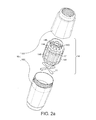
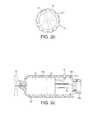
- Figures 2a , 2b and 2c show an exploded view, a radial cross-section and an axial cross-section of the first embodiment, respectively. These figures are collectively referred to as Figure 2 , since they show the same structure each in a different manner.
- flow sensor 1 includes a turbine 11 and a water-sealed capsule 14, the water-sealed capsule 14 enclosing an electrical generator 12 coupled to the turbine 11 and an RF transmitter 13.
- the generator activates the transmitter to send an actuation control signal to the pump E.
- the water-sealed capsule 14 is provided as two parts, namely capsule body 145 and capsule cap 146 which fit together to enclose an inner void of the capsule in which the generator 12 and transmitter 13 are provided.
- the capsule 14 is configured to be disposed within shell 16, which comprises two halves, an upper half 161 and a lower half 162.
- the capsule cap 146 is provided with a screw thread 143 to engage with the upper half 161 of the shell 16 and to retain the capsule securely therein, centred on the axis of the shell 16 in the direction of water flow.
- the shell is further provided with screw threads to couple the upper half 161 and lower half 162 together and two further screw threads to couple the upper half 161 to an upstream location from which water is supplied and the lower half 162 to a downstream location to which water is provided.
- These threads are configured for engagement with a conventional shower hose fitting, but in other embodiments alternative connectors may be provided, such as press-fit connectors or hose-clamps.
- Capsule 14 is provided with apertures 144 and ribs 141 which allow water received at the inlet of upper shell 161 to flow easily past the flow sensor 1, past the turbine 11 and through the outlet of lower shell 162. While it may appear that these ribs define cut-outs which are small in the sectional area compared to the cross-sectional area of the capsule 14, such a configuration nevertheless allows a sufficient quantity of water to pass to both drive turbine 11 and to provide sufficient flow for a shower from the outlet of lower shell 162.
- the ribs 141 also prevent vortices associated with the turbine 11 from forming around the capsule 14. Such ribs, however, are not essential to the present invention, and a smooth or helical surface may be provided, for example.
- LEDs (light emitting diodes) 17 are optionally provided, located in the interstices between ribs 141. In the present embodiment, these LEDs are configured to illuminate when the transmitter 13 is activated, thus confirming that the flow sensor 1 is correctly operating. This is particularly advantageous when the intended user is hard of hearing or otherwise perceptually impaired, or when a low-noise pump is installed.
- at least upper shell 161 is provided as a translucent material, preferably a translucent plastic.
- upper shell 161 and lower shell 162 may be provided either as opaque plastic, stainless steel, or another suitable material. Of course, other illuminable indicators may be used instead of LEDs.
- FIG. 2b Visible most easily in Figure 2b are capsule 14, ribs 141, LEDs 17 and the position of turbine 11, shown in dotted outline. It can be seen from Figure 2b that, if it is not desired to provide the LEDs 17, the available flow channels between ribs 14 may become wider and an even higher water throughput is possible.
- FIG. 2c Visible in Figure 2c is the arrangement of the turbine 11 driving the generator 12 via a drive shaft 11a.
- the generator is electrically connected to transmitter 13 which is also connected to battery 15 and LED 17.
- the entire construction is enclosed within capsule 14, comprising capsule body 145 and capsule cap 146.
- a rib 141 is only shown on one side of Figure 2c , since, as can be seen from Figure 2b , in the present embodiment each rib faces a flow channel with an LED in it on the diametrically opposite side. This however, is purely arbitrary, and the number of channels and LEDs may be varied within normal design constraints. Indeed, some of the channels may be provided with LEDs and others without LEDs, as the designer wishes.
- water flows in at the inlet of the capsule and passes through apertures 144 formed in cap 146. The water then flows through the channels formed between the ribs 141 to pass the turbine 11.
- the turbine 11 rotates and causes the generator 12 to provide power to the transmitter 13.
- the transmitter 13 Once the transmitter 13 is supplied with a sufficiently high voltage from the generator, indicating a sufficient flow of water through the flow sensor, the transmitter transmits a radio frequency signal which is received by the pump E to indicate that the pump should be activated.
- LED 17 is illuminated to indicate that the transmitter is successfully transmitting.
- Rechargeable batter 15 may, for example, be a conventional NiMH cell or be a lithium iron or lithium polymer cell. In other embodiments, the battery may be a regular non-rechargeable cell, which the user would replace on a periodic basis. The purpose of the battery is to supply sufficient power to the transmitter to ensure reliable operation even with variations in the flow speed of the water.
- variant embodiments without the use of a battery, rechargeable or otherwise.
- Such a variant embodiment could rely on the flow of water being sufficiently stable to maintain adequate power to the transmitter, or could incorporate a capacitor to smooth the power supply.
- a conventionally-obtainable charge controller circuit is incorporated in the transmitter to avoid overcharging of the battery.
- the code sent by the transmitter is a sequence of codes forming a rolling code transmitted at a code word rate of ten per second.
- the code sequence is transmitted for as long as the turbine is rotating at a sufficiently high rate to generate the pre-determined voltage for activation of the transmitter, and the pump is configured to operate for as long as the signal is being received.
- the turbine spins down and the transmitter stops sending the code sequence.
- the pump then ceases operation, after having failed to receive a pre-determined number of code words.
- the number of code words required not to be received before the pump terminates is set preferably to be greater than one in order to avoid intermittent operation of the pump due to interference.
- the transmitter may alternatively be configured to operate the pump on a variety of different transmission regimes, for example by sending a first signal to the pump to begin pumping and a second signal to the pump to stop pumping.
- a single continuous or repeating signal at a defined frequency may be used instead of a rolling code sequence to signal the pump that operation should be continued.
- transmitters, receivers, and signalling schemes available for wireless communication, the only requirement being that the transmitter is able to provide a sufficiently powerful signal when powered by the turbine and/or the battery and that the receiver be suitably sensitive to receive the transmission through potentially a number of intervening walls.
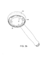
- the second embodiment is shown in Figures 3a , 3b and 3c , and is designed to be installed to replace an existing shower head fixture rather than to be in-line between a water supply and a shower hose, as in the first embodiment.
- Such an embodiment is of particular use when the shower configuration involves a shower head directly installed to an outlet in a ceiling or a wall, in other words when no or little intervening shower hose between wall or ceiling and shower head is available.
- the second embodiment has a shell 262 formed in the shape of a shower head into which an appropriately shaped water-sealed capsule 244 having mounted thereon a turbine 21 is inserted.
- An 0-ring 28 is provided between the capsule 24 and an inner partition structure 262b of shell 262 which surrounds the turbine 21.
- the capsule 24 contains a generator, transmitter and battery (not shown), which operate in the same way as those of the first embodiment.
- the capsule 24 is again provided with apertures 244 to allow the passage of water after energy has been extracted by the turbine, and there is provided a rose plate 261 which forms a pre-determined pattern of water jets to create the shower effect.
- the rose plate 261 is provided with a screw thread which engages with the corresponding screw thread on shell 262 to compress and retain the capsule 24 containing the generator and transmitter in situ.
- FIG. 3b A partially assembled view of this second embodiment is shown in Figure 3b , lacking the rose plate 261 but showing LEDs 27 mounted on a downstream surface of capsule 24 to illuminate the interior surface of rose plate 261 when the transmitter transmits a pump control signal, as in the first embodiment. If rose plate 261 is a translucent material, the LEDs will be visible to the user, while if it is an opaque material their effect will be seen in the streams of water exiting rose plate 261.
- FIG. 3c shows the particular operation of the turbine in the second embodiment of the present invention.
- Water enters the shower head shaped shell 262 via an upstream threaded connector, normally from a shower hose or a fixed pipe.
- Water passes the length of the handle of the shower head and exits through entrance aperture 262a to the interior of partition member 262b which surrounds the turbine.
- the water is forced past the turbine due to the slightly offset position of entrance aperture 262a and exits through exit aperture 262c to the space outside the partition member.
- the water is then free to exit the shower head via the rose plate 261.
- energy is extracted from the water by means of rotation of the turbine 21 sufficient to power the transmitter and, if required, to charge the battery.
- All elements of the present embodiment may preferably be constructed from ABS plastic, except for the O-rings which may preferably be constructed from butyl rubber, and the generator, transmitter, battery and LEDs which are preferably provided as conventional electronic commodity components.
- Figure 4 shows the first embodiment of the present invention installed in a water supply system together with a power shower pump P.
- Water is stored in warm water store W and pressure for the system is supplied in cold water storage reservoir R.
- Cold water storage reservoir R is fed by a connection to the mains water supply.
- the pressure from cold water reservoir R is sufficient to drive warm water from the warm water storage tank W through the pump P along hose H and out of shower head S.
- cold water may be fed directly from the cold water reservoir R through pump P, mixer tap M and to shower head S.
- the mixed water flow flows past the flow sensor 1 which is an embodiment of the invention similar or identical to the first embodiment hereinbefore described. This small flow of water is sufficient to cause the flow sensor 1 to generate a control signal to cause the pump P to activate, and thereby supply the full desired water pressure for an effective shower.
- flow sensor 1 in this embodiment is similar or identical to the first embodiment, it will of course be appreciated that instead the flow sensor may be similar or identical to the second embodiment described above with reference to Figures 3a , 3b and 3c .
- the transmitter may activate simultaneously any other type of bathroom pump which it is prudent to engage during showering activities.
- the pump E for extracting water from gulley G may be activated in addition to activation of the power shower pump P.
Landscapes
- Engineering & Computer Science (AREA)
- Physics & Mathematics (AREA)
- General Physics & Mathematics (AREA)
- Fluid Mechanics (AREA)
- Life Sciences & Earth Sciences (AREA)
- General Engineering & Computer Science (AREA)
- Health & Medical Sciences (AREA)
- Mechanical Engineering (AREA)
- Hydrology & Water Resources (AREA)
- Public Health (AREA)
- Water Supply & Treatment (AREA)
- Chemical & Material Sciences (AREA)
- Combustion & Propulsion (AREA)
- Bathtubs, Showers, And Their Attachments (AREA)
Applications Claiming Priority (1)
| Application Number | Priority Date | Filing Date | Title |
|---|---|---|---|
| GB1003410A GB2478290A (en) | 2010-03-01 | 2010-03-01 | Flow sensor for wirelessly controlling a shower pump or shower waste water pump |
Publications (1)
| Publication Number | Publication Date |
|---|---|
| EP2363538A2 true EP2363538A2 (fr) | 2011-09-07 |
Family
ID=42125806
Family Applications (1)
| Application Number | Title | Priority Date | Filing Date |
|---|---|---|---|
| EP11156154A Withdrawn EP2363538A2 (fr) | 2010-03-01 | 2011-02-28 | Capteur de débit pour contrôler une pompe de douche |
Country Status (2)
| Country | Link |
|---|---|
| EP (1) | EP2363538A2 (fr) |
| GB (1) | GB2478290A (fr) |
Cited By (3)
| Publication number | Priority date | Publication date | Assignee | Title |
|---|---|---|---|---|
| CN113049032A (zh) * | 2021-03-11 | 2021-06-29 | 安徽皖水水务发展有限公司 | 一种泵房防淹水预警系统 |
| CN115151731A (zh) * | 2020-03-03 | 2022-10-04 | Ksb股份有限公司 | 用于提高至少一个取用点或液压消耗器的供水中的供给压力的压力提高设备 |
| GB2601706B (en) * | 2017-12-21 | 2022-10-05 | Kohler Mira Ltd | A flow dispersion device |
Families Citing this family (1)
| Publication number | Priority date | Publication date | Assignee | Title |
|---|---|---|---|---|
| GB201020421D0 (en) * | 2010-12-02 | 2011-01-19 | Munster Simms Eng Ltd | Shower pump system with diagnostic capabilities |
Family Cites Families (3)
| Publication number | Priority date | Publication date | Assignee | Title |
|---|---|---|---|---|
| US4936508A (en) * | 1989-05-02 | 1990-06-26 | Ingalz Thomas J | Shower head volume meter with alarm signal |
| WO2006110600A2 (fr) * | 2005-04-08 | 2006-10-19 | H20Flo, Llc | Systeme et procede de surveillance, d'enregistrement et de facturation d'un appareil sanitaire individuel et unite d'utilisation de l'eau dans une structure multi-unite |
| GB0509258D0 (en) * | 2005-05-06 | 2005-06-15 | Munster Simms Eng Ltd | A system for controlling the rate of a pump on a water drainage outlet of a water dispensing unit |
-
2010
- 2010-03-01 GB GB1003410A patent/GB2478290A/en not_active Withdrawn
-
2011
- 2011-02-28 EP EP11156154A patent/EP2363538A2/fr not_active Withdrawn
Non-Patent Citations (1)
| Title |
|---|
| None |
Cited By (4)
| Publication number | Priority date | Publication date | Assignee | Title |
|---|---|---|---|---|
| GB2601706B (en) * | 2017-12-21 | 2022-10-05 | Kohler Mira Ltd | A flow dispersion device |
| CN115151731A (zh) * | 2020-03-03 | 2022-10-04 | Ksb股份有限公司 | 用于提高至少一个取用点或液压消耗器的供水中的供给压力的压力提高设备 |
| CN113049032A (zh) * | 2021-03-11 | 2021-06-29 | 安徽皖水水务发展有限公司 | 一种泵房防淹水预警系统 |
| CN113049032B (zh) * | 2021-03-11 | 2022-05-03 | 安徽皖水水务发展有限公司 | 一种泵房防淹水预警系统 |
Also Published As
| Publication number | Publication date |
|---|---|
| GB2478290A (en) | 2011-09-07 |
| GB201003410D0 (en) | 2010-04-14 |
Similar Documents
| Publication | Publication Date | Title |
|---|---|---|
| CA2846169C (fr) | Dispositif de douche a l'ozone | |
| EP3048084B1 (fr) | Système de filtre de robinet à commande à distance | |
| KR20100105466A (ko) | 무선으로 전력공급되는 디스펜서 시스템 | |
| US20180363639A1 (en) | Electronic systems for controlling submersible pumps | |
| US11236752B2 (en) | In-line pressure boosting system and method | |
| EP2363538A2 (fr) | Capteur de débit pour contrôler une pompe de douche | |
| US10035150B2 (en) | System for supplying additive fluids within a waste disposal water supply system | |
| US20180022618A1 (en) | Water recycling system and method | |
| US20110036761A1 (en) | Automatic ozone water output device | |
| US9696728B2 (en) | Secondary water supply system for a waste disposal | |
| CA3051732A1 (fr) | Module, systemes et procedes de sterilisation de l`eau | |
| WO2016076784A1 (fr) | Appareil et unité de douche portative associée pour alimentation en eau et à des fins sanitaires, par exemple pour permettre l'épuration et le recyclage d'eau ou le rejet d'eau | |
| JP2017179742A (ja) | 便器洗浄装置 | |
| EP2363540A2 (fr) | Bac de douche automatique ou rigole de salle d'eau | |
| CN108603366A (zh) | 洗手装置 | |
| KR101312599B1 (ko) | 간이 스프링클러용 소방용수 공급장치 | |
| US10538901B2 (en) | Modular electrical appliance which reuses greywater | |
| KR100879021B1 (ko) | 상수도 수압을 이용한 에너지 발생장치 | |
| CN105625521A (zh) | 净水机废水回收系统 | |
| JP2006015232A (ja) | 滞留水の滞留検知システム | |
| JP7811354B2 (ja) | 電動排水栓装置 | |
| US20240157378A1 (en) | Water Conserving Showerhead and Associated Methods of Use | |
| JP5918524B2 (ja) | 湯水混合水栓 | |
| JP7122572B2 (ja) | トイレ用手洗い器システム | |
| JP2005320712A (ja) | ホース収納式水栓 |
Legal Events
| Date | Code | Title | Description |
|---|---|---|---|
| PUAI | Public reference made under article 153(3) epc to a published international application that has entered the european phase |
Free format text: ORIGINAL CODE: 0009012 |
|
| AK | Designated contracting states |
Kind code of ref document: A2 Designated state(s): AL AT BE BG CH CY CZ DE DK EE ES FI FR GB GR HR HU IE IS IT LI LT LU LV MC MK MT NL NO PL PT RO RS SE SI SK SM TR |
|
| AX | Request for extension of the european patent |
Extension state: BA ME |
|
| STAA | Information on the status of an ep patent application or granted ep patent |
Free format text: STATUS: THE APPLICATION IS DEEMED TO BE WITHDRAWN |
|
| 18D | Application deemed to be withdrawn |
Effective date: 20130903 |