EP2363540A2 - Automatische Duschwanne oder Feuchtraumabfluss - Google Patents
Automatische Duschwanne oder Feuchtraumabfluss Download PDFInfo
- Publication number
- EP2363540A2 EP2363540A2 EP11156152A EP11156152A EP2363540A2 EP 2363540 A2 EP2363540 A2 EP 2363540A2 EP 11156152 A EP11156152 A EP 11156152A EP 11156152 A EP11156152 A EP 11156152A EP 2363540 A2 EP2363540 A2 EP 2363540A2
- Authority
- EP
- European Patent Office
- Prior art keywords
- float
- gulley
- sensor
- pump
- waste water
- Prior art date
- Legal status (The legal status is an assumption and is not a legal conclusion. Google has not performed a legal analysis and makes no representation as to the accuracy of the status listed.)
- Withdrawn
Links
Images








Classifications
-
- E—FIXED CONSTRUCTIONS
- E03—WATER SUPPLY; SEWERAGE
- E03F—SEWERS; CESSPOOLS
- E03F5/00—Sewerage structures
- E03F5/04—Gullies inlets, road sinks, floor drains with or without odour seals or sediment traps
- E03F5/0407—Floor drains for indoor use
- E03F5/0408—Floor drains for indoor use specially adapted for showers
-
- A—HUMAN NECESSITIES
- A47—FURNITURE; DOMESTIC ARTICLES OR APPLIANCES; COFFEE MILLS; SPICE MILLS; SUCTION CLEANERS IN GENERAL
- A47K—SANITARY EQUIPMENT; ACCESSORIES THEREFOR, e.g. TOILET ACCESSORIES
- A47K3/00—Baths; Showers; Appurtenances therefor
- A47K3/28—Showers or bathing douches
-
- A—HUMAN NECESSITIES
- A47—FURNITURE; DOMESTIC ARTICLES OR APPLIANCES; COFFEE MILLS; SPICE MILLS; SUCTION CLEANERS IN GENERAL
- A47K—SANITARY EQUIPMENT; ACCESSORIES THEREFOR, e.g. TOILET ACCESSORIES
- A47K3/00—Baths; Showers; Appurtenances therefor
- A47K3/28—Showers or bathing douches
- A47K3/40—Pans or trays
-
- E—FIXED CONSTRUCTIONS
- E03—WATER SUPPLY; SEWERAGE
- E03C—DOMESTIC PLUMBING INSTALLATIONS FOR FRESH WATER OR WASTE WATER; SINKS
- E03C1/00—Domestic plumbing installations for fresh water or waste water; Sinks
- E03C1/12—Plumbing installations for waste water; Basins or fountains connected thereto; Sinks
-
- E—FIXED CONSTRUCTIONS
- E03—WATER SUPPLY; SEWERAGE
- E03C—DOMESTIC PLUMBING INSTALLATIONS FOR FRESH WATER OR WASTE WATER; SINKS
- E03C1/00—Domestic plumbing installations for fresh water or waste water; Sinks
- E03C1/12—Plumbing installations for waste water; Basins or fountains connected thereto; Sinks
- E03C1/122—Pipe-line systems for waste water in building
- E03C1/1222—Arrangements of devices in domestic waste water pipe-line systems
- E03C1/1227—Arrangements of devices in domestic waste water pipe-line systems of pumps for facilitating drawing off
-
- E—FIXED CONSTRUCTIONS
- E03—WATER SUPPLY; SEWERAGE
- E03C—DOMESTIC PLUMBING INSTALLATIONS FOR FRESH WATER OR WASTE WATER; SINKS
- E03C1/00—Domestic plumbing installations for fresh water or waste water; Sinks
- E03C1/12—Plumbing installations for waste water; Basins or fountains connected thereto; Sinks
- E03C1/22—Outlet devices mounted in basins, baths, or sinks
-
- E—FIXED CONSTRUCTIONS
- E03—WATER SUPPLY; SEWERAGE
- E03C—DOMESTIC PLUMBING INSTALLATIONS FOR FRESH WATER OR WASTE WATER; SINKS
- E03C1/00—Domestic plumbing installations for fresh water or waste water; Sinks
- E03C1/12—Plumbing installations for waste water; Basins or fountains connected thereto; Sinks
- E03C1/24—Overflow devices for basins or baths
-
- E—FIXED CONSTRUCTIONS
- E03—WATER SUPPLY; SEWERAGE
- E03F—SEWERS; CESSPOOLS
- E03F5/00—Sewerage structures
- E03F5/22—Adaptations of pumping plants for lifting sewage
Definitions
- the present invention relates to a gulley for a shower tray or wet-room, and particularly to a gulley which is able to facilitate activation of a pump for removing waste water from the shower tray or wet-room as required by the presence or absence of waste water in the gulley.
- waste water is to be understood as any waste liquid that may be present in a bathroom environment, including without limitation clean, contaminated or dirty water, and cleaning product solutions, etc.
- the most common solution to this problem is to provide a flow switch upstream of the shower outlet which activates the pump on detection of a flow of water into the shower outlet and thus into the shower tray or wet room.
- Such switches are typically installed in concealed spaces between a water storage tank and the shower facility. Over time, such flow switches can suffer fouling of working parts due to particulate debris in the water supply.
- the usual solution to this problem is to provide a water filter with the flow switch. However, over time, the water filter itself often becomes clogged, leading to restriction of flow and failure of the flow switch to operate. In such cases, the flow switch is frequently difficult to relocate and, once located, to access for cleaning, repair or replacement.
- a float switch which relies on a ring-shaped float arranged to slide along a vertical post passing through the centre of the ring such that it can close electrical contacts at particular heights on the post and thus indicate a relative level of water in the gulley.
- the present invention has found that, when such a float switch is used in a shower, hair has a tendency to become entangled between the post and the float and, over time, tends to foul the clearance between post and float so as to inhibit correct operation of the switch.
- a gulley for a shower tray or wet-room comprising a chamber having an inlet for waste water and an outlet for connection to a pump; a magnetic element; a magnetic sensor; a float; and a confining structure, wherein one of the magnetic sensor and the magnetic element is arranged in the float; the confining structure surrounds the float, with the float being freely movable within the confines of the confining structure; and the float is arranged for movement within the confines of the confining structure so that the relative position of the magnetic sensor and the magnetic element changes in dependence upon the level of waste water within the chamber.
- Such an arrangement is able to provide an automatic gulley which can reliably and rapidly activate a pump based on the level of waste water in the gulley and which reduces the likelihood of the mechanism being fouled by local contaminants, hair, scum, and the like.
- shower tray or wet-room here encompasses any such facility found in a domestic, health care, or similar facility, where water is caused to impinge on a human body in a designated wet region for the purposes of hygiene, relaxation, or similar.
- the wet area can be provided in an enclosed, semi-enclosed, or entirely open location, depending on the design and user requirements.
- the magnetic sensor may be a Hall-effect sensor, a reed switch, or other device able to react to a local magnetic field.
- the float is any element which, when immersed in waste water, such as might reasonably be found in a shower or wet-room, will be buoyed upward by the water.
- An embodiment of the gulley of the present invention is provided wherein the magnetic sensor is arranged to generate and output a control signal for controlling the pump in dependence upon the relative position of the magnetic sensor and the magnetic element.
- the control logic of the pump allows the control logic of the pump to be provided in a simplified manner wherein a control signal from the sensor is monitored and the pump is activated on the basis of the control signal.
- Such an arrangement permits a variety of commodity pumps to be used together with an extremely simple controller controlling the power to the pump on the basis of the control signal from the sensor.
- the control signal here may be logic 1 or 0 defined with reference to a standardised signalling scheme, may be a first voltage for activation and a second voltage for deactivation of the pump, may be an open-circuit/closed-circuit condition, or any other electrical or electronic signalling scheme of which the skilled person may be aware.
- An embodiment of the present invention is provided wherein: the magnetic sensor is provided at a fixed position on the bottom surface of the chamber; the magnetic element is arranged in the float, and the float is arranged for movement so that it rises away from the magnetic sensor as the level of waste water within the chamber rises.
- An embodiment of the present invention is provided wherein the magnetic element is formed as part of the float. Such an embodiment is able to improve retention of the magnetic element relative to the float.
- the gulley may be provided wherein the confining structure is a structure arranged in the chamber to constrain the float to move in a substantially linear path, the confining structure being provided with at least one inlet for waste water.
- the confinement to a substantially linear path here should not be construed to necessarily prevent axial rotation about the path, but prevents substantial longitudinal deviation of an axis of the float from the path. Such a configuration allows for easy maintenance should fouling occur.
- the magnetic interaction of the element with the sensor is highly repeatable for a given level of waste water in the chamber.
- a gulley wherein the chamber is provided with a housing on an inside wall thereof; the sensor is provided in the housing on the inside wall; and the housing is configured to permit access to the magnetic sensor through the inlet and the chamber.
- Such an arrangement is able to provide a particularly low-maintenance configuration, wherein failure of the sensor may be remedied by removal and replacement of the sensor without the need to disassemble the gulley, the shower tray, or the local area to obtain access.
- the housing has a removable cover configured to re-sealably segregate the interior of the housing from waste water in the chamber.
- a removable cover configured to re-sealably segregate the interior of the housing from waste water in the chamber.
- the confining structure is configured to be releasably attachable to the housing.
- Such a configuration provides an improved arrangement wherein disassembly and re-assembly of the gulley may be easily and efficiently accomplished.
- the confining structure comprises a cap which encloses the float.
- a cap which encloses the float.
- the confining structure defines a tapered confine arranged to guide the float to a predetermined position as the water level in the gulley drops.
- Such an arrangement is able to provide a repeatable sensor reading for any given water level in the gulley.
- such a configuration may also be provided to guide the float to a predetermined position as the water level in the gulley rises.
- Such an arrangement provides an equivalent effect to the aforementioned alternative, except that it is applicable to those situations where one of the sensing element or the magnetic element is provided at the top, rather than at the bottom, of the chamber.
- the float is substantially spherical. Such an arrangement allows the float to rotate arbitrarily during use as a result of turbulent eddies in the waste water which action of rotation enables the float to self-clean by dislodging contamination on the surface.
- the magnetic element is arranged within the float for free movement within the confines thereof.
- Such an arrangement contributes to the free rotation action of the float to dislodge contaminants whilst ensuring that the magnetic element always moves to the lowest position within the float so that it can be reliably and repeatedly detected by the magnetic sensor as the float approaches the magnetic sensor.
- the magnetic element may be substantially spherical to facilitate free movement.
- the confining structure of the gulley comprises an inner surface of the chamber. Such an arrangement is able to provide reduced complexity of manufacture.
- the float in use, rests on a rest surface when no waste water is present in the chamber, and at least one of the rest surface and the surface of the float opposed to the rest surface is provided with at least one projection.
- the provision of the projection minimises the contact surface area between the float and the surface on which it may come to rest such that the collection of scum and contaminants is minimised and adhesion between the float and the surface may be reduced even when contamination is present.
- the magnetic sensor is configured to exhibit a first detectable condition when the float is beyond a pre-determined distance from the magnetic sensor; and the magnetic sensor is configured to exhibit a second detectable condition when the float is within the pre-determined distance from the magnetic sensor.
- the predetermined distance is a distance relating to a level of waste water in the chamber where the level of waste water is a level which at least partially covers the outlet of the chamber.
- the chamber is provided with a partition member between the inlet and the outlet; and the pre-determined distance is a distance related to a level of waste water at which fluid communication between the inlet and the outlet passes through a portion of the waste water in the gulley.
- the pre-determined distance is a distance related to a level of waste water at which fluid communication between the inlet and the outlet passes through a portion of the waste water in the gulley.
- the gulley By providing the partition member between the inlet and the outlet and setting the pre-determined distance to be a distance related to a level of waste water at which fluid communication between the inlet and the outlet passes through a portion of the waste water, the gulley will activate when there is sufficient waste water in the gulley for suction on the outlet side of the partition member to draw the waste water into the outlet even in cases when the absolute level of waste water is significantly below the level of the outlet.
- the level of waste water is such that fluid communication between the inlet and the outlet need not pass through a portion of the waste water
- application of suction to the outlet will merely draw air directly from the inlet to the outlet over the surface of the waste water. In this latter case, application of suction will do little to empty the gulley.
- the gulley further comprises an illuminable indicator; and the illuminable indicator is configured to indicate a detectable condition of the sensor.
- Such configurations are able to provide information to a user about the operating condition of, among other factors, the working of the gulley and to provide, for example, a reassuring indication to show that the gulley is operating appropriately and/or a warning indication to show that the gulley is not operating or is failing.
- the illuminable indicator may be configured to illuminate in a range of indicative conditions dependent on factors in addition to the status of the sensor, for example on the basis of signals from one or more flow sensors indicating that at least one shower fixture in the wet area is being operated and water is being provided thereto and/or signals from the pump itself indicating that it is operating or is in a failure state.
- kits of parts for use in assembling the shower or wet-room gulley comprising a magnetic sensor, a magnetic element, a float, and a confining structure for surrounding the float within the gulley so that the float is freely movable within the confines of the confining structure.
- the kit of parts may provide the confining structure as a cap.
- the kit of parts may further comprise a bottom portion for connection to a gulley to form a chamber for waste water.
- a kit of parts permits a conventional shower gulley having an opening at the bottom for fitment of various types of standardised bases to be provided with the working parts of the shower gulley of the present invention.
- the magnetic sensor may be configured to fit within a housing on the bottom portion.
- the confining structure may be configured to fit over the housing; and the float may be configured to fit within the confining structure.
- the float may be substantially spherical.
- the magnetic element may be arranged within the float for free movement within the confines thereof.
- the magnetic element may be substantially spherical.
- Figure 1 shows a shower installation having an embodiment of the shower gulley of the present invention installed.
- a shower tray T is located beneath a shower outlet S, and the shower tray T is provided with a cut-out for the shower gulley 1 to be placed therein.
- the shower outlet S is connected to the local water supply via shower hose H and mixer valve M.
- An in-line flow sensor F is here optionally provided in line with hose H to detect water flow from the shower outlet S and to activate a power shower booster pump as described in co-pending application entitled "FLOW SENSOR FOR CONTROLLING A SHOWER PUMP" (attorney reference P19967), assigned to the present Applicants and filed on the same date as the present application, the entire contents of which are herewith incorporated by reference.
- a pump P is provided for applying suction to the outlet of the gulley 1, thereby drawing waste water from the gulley 1 by means of an outlet hose O and passing the waste water downstream to a conduit C for connection to a sewer or other waste handling system.
- the irregular line in Figure 1 passing through the cut-out for the gulley 1, displays the region underneath the shower tray T and behind the wall where the pump P is located.
- Distribution power supply D is also shown behind the wall for delivering power to the pump.
- the pump P may indeed be some distance away, and even provided in another room, for example one which backs onto the shower area, for ease of servicing.
- a cable 123 is provided between the gulley 1 and the pump P for the transmission of power from the power supply D to the gulley 1 and for the transmission of signals between the gulley 1 and the pump P.
- the gulley G is able to facilitate reliable activation of the pump P by outputting a control signal to pump P via control cable 123 in dependence upon the level of waste water present in the gulley.
- the gulley contains a magnetic sensor fixed in its base and a magnetic element located inside a float which moves relative to the magnetic sensor in dependence upon the level of water within the gulley, so that magnetic field sensed by the magnetic sensor changes in dependence upon the water level.
- the control signal for pump P is generated in accordance with the sensed magnetic field.
- Figure 1 shows a shower tray T
- a shower gulley according to an embodiment of the present invention may be used in other shower installations such as in wet-rooms, but in such cases the tray is absent, and the gulley is provided at a lowest point of the wet area floor.
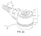
- Figure 2a , 2b and 2c show a first embodiment of the shower gulley 1 of the present invention.
- Figure 2a is a perspective view
- Figure 2b is an exploded view showing each component.
- Figure 2c shows a cross-section of the gulley.
- the shower gulley 1 of the first embodiment has a chamber 11 which comprises a main portion 111, a bottom portion 112 which engages with the main portion 111 by means of a screw thread, and a top portion 113 which engages with a top aperture of the main portion 111 and is provided with a lip to sandwich a portion of the shower tray T which surrounds the cut-out for the gulley in between the top portion and the main portion.
- the top portion 113 defines an inlet 116 for waste water to enter the gulley, into which is located a removable filter insert 115. Thus, water accumulating in the tray T will pass through the inlet 116 and into the chamber 11.
- the filter insert 115 provides a first-line filtering of the waste water for hair and foreign objects, and may easily be removed for cleaning. In contrast, once installed, the top portion 113 and the main portion 111 are generally left in place.
- the main portion 111 also has an outlet 117 through which waste water may be extracted by suction from pump P.
- an adaptor 18 is provided, comprising a step-down extension piece 181, screw cap 182 and O-ring 183, which connects to a surrounding portion of outlet 117 to permit further connection to any regular pump hose, of which hose O of Figure 1 is an example.
- extension portion 181 is provided with barbs to facilitate secure connection of flexible hose O thereto.
- gulley that has been described to this point is entirely conventional.
- Such gulleys are obtainable as a commodity part, and it is usual practice to provide a bottom portion, similar in general shape to bottom portion 112, in the shape of a cup which is screwed onto the lower screw thread of main portion 111 to form an enclosed chamber where waste water may collect and from which it may be extracted.
- additional components and a particular form of bottom portion 112 are provided as described below to sense the level of water in the chamber 11 and to output a control signal to facilitate activation of the pump P in dependence upon the water level.
- the additional components and particular bottom portion 112 of the present embodiment may thus be provided, for example by retrofitting, to any suitable commodity gulley in order to realise an embodiment of the invention.
- bottom portion 112 in the present embodiment has a sensor 12 provided therein.
- the sensor 12 comprises a plurality of sensor elements 121 and a circuit board 122 from which cable 123 leads.
- each of the sensor elements is a Hall sensor; however, any magnetic sensor may be used in sensor 12, for example a reed switch, normally open or normally closed.
- the provision of four identical sensors provides redundancy in the case of sensor failure. In this case, if one sensor gives an output which differs significantly from the average of the other sensors, its output is disregarded. Thus the operational life of the sensor can be prolonged.
- each Hall sensor draws power via cable 123, which power is ultimately derived from the pump supply D, and a control signal is generated and output to pump P via cable 123 in dependence upon the local magnetic field sensed by sensor elements 121.
- a housing 15 is also provided to enclose the sensor 12 and seal it from waste water in the chamber 11.
- the housing 15 comprises an enclosure 151, which in this embodiment forms part of the inside surface of the bottom portion 112, a cover 152 for the enclosure and an O-ring 153.
- This construction permits a conventional circuit board 122 e.g. with solder terminals or similar connection means to be used as a substrate for the sensor 12, and the signalling wire 123, which connects to the pump P and provides the output from the sensor 12 to the pump P, to exit the bottom portion 112 through a hole in a lower surface of the enclosure 151 without the need for any particular special sealing in the sensor 12 or the wire 123.
- cover 152 connects to enclosure 151 by means of a screw thread so that it can be attached by screwing and removed by unscrewing, although other possibilities, such as press-fit or snap-fit are permissible.
- float 13 comprising upper portion 131, lower portion 132 and magnetic element 133.
- magnetic element 133 is retained in a captive configuration inside lower portion 132, in the present embodiment by epoxy adhesion between the magnetic element 133 and retaining structure 134.
- Top portion 133 snap-fits to lower portion 132 to provide an air- and water-tight seal between the interior and exterior of the float 13.
- the magnetic element 133 is provided in float 13, which will in use be located at a position relative to the sensor element 121 dependent upon the level of waste water in the chamber 11, a magnetic interaction between the sensor 12 and the magnetic element in the float 13 is dependent upon the distance therebetween, and thus the output of the sensor 12 is directly dependent upon the level of waste water in the chamber.
- the pump is therefore activated on the basis of an output of the sensor 12 so as to provide suction when necessary due to an excess of waste water in the chamber 11.
- the bottom portion 112 of the gulley is also provided with a confining structure which, in this embodiment, has the form of a removable cap 14, which has an aperture 141 formed therein to allow waste water to enter.
- the cap 14 is arranged to snap-fit over the cover 152 of the enclosure 151, which houses the sensor 12, to enclose the float 13.
- the cap 14 surrounds the float 13, while allowing the float 13 to remain freely movable within the confines of the cap.
- the cap 14 functions to constrain the movement of the float 13 to a substantially linear path in a vertical direction over the sensor 12.
- the cap 14 also diverts hair, scum and other contaminants away from the float 13 to minimise the risk of such contaminants fouling the movement of the float 13.
- the float 13 is constrained by the relative diameters of the inner surface of cap 14 and outer surface of float 13 to move in a substantially linear path towards and away from sensor 12, dependent on the waste water level in the chamber. Due to the barrel-shape of the float 13 and the small gap between the float outer surface and the cap inner surface, the float 13 moves easily up and down relative to the sensor 12 but cannot significantly move sideways or overturn. This ensures that the relative positions of sensor 12 and float 13 are repeatable for a given level of water.
- lower portion 132 of float 13 has formed, on its bottom surface, projections 134, in the present embodiment in the form of ridges. These ridges provide a reduced contact surface area between the bottom surface of float 13 and top surface of cover 152, to reduce the possibility of adhesion between the two due to accumulation of scum or other contaminants. This ensures that the float remains free to move even if the gulley becomes contaminated.
- Cable management cover 17 is provided as a snap-fit beneath bottom portion 112 to contain excess cable 123 and also to provide ease of routing of the cable from the gulley 1 to the pump P.
- the configuration of the gulley of the first embodiment described above allows easy maintenance and repair.
- the filter element 115 may be removed, together with cap 14 and float 13, via inlet 116, cover 152 removed and sensor 12 then lifted up through the inlet 116, drawing excess cable 123 with it, and repaired or replaced without need for access to the exterior of the gulley, which is relatively inaccessible beneath the shower tray.
- the excess cable may be fed back through the hole in the bottom surface of enclosure 151, the sensor relocated in enclosure 151 and the 0-ring 153 and cover 152 replaced to re-seal the sensor from any waste water in the gulley.
- the float 13, cap 14 and filter insert 115 may then be replaced and the gulley put back into operation.
- the senor is configured to be in a first state when the float is less than a pre-determined distance from the sensor and in a second state when the float is beyond the pre-determined distance from the sensor.
- the first and second states which may be provided as a high voltage (12 volts) and a low voltage (4 volts), may then be used to directly drive a relay, having, for example, an activation voltage of 10 volts, which controls power to the pump.
- the relay in this case would be functioning as a controller, controlling the pump on the basis of the sensor output, although more sophisticated variants employing electronic logic are possible.
- the first condition could be, for example, a voltage less than 6 volts and the second condition would be, for example, a voltage greater than or equal to 6 volts.
- the controller could then include a voltage comparator on which basis the pump could be activated.
- the senor 12 may comprise, for example, a reed switch, and thus may change between open-circuit and closed-circuit conditions on the basis of the relative movement of the float 13.
- Reed switches may be selected that open and/or close at particular field strengths. It is within the ambit of the skilled reader to match gulley, sensor and magnet to achieve an appropriate change in the condition of the sensor 12 when the float 13 is at an appropriate height.
- any sensor capable of detecting a change in a magnetic field is in principle usable, and it will be within the capability of the skilled reader to implement the appropriate control electronics for any given sensor.
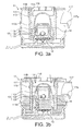
- Figures 3a, 3b , 3c and 3d show one possible activation sequence for the gulley in operation.
- FIG 3a there is no waste water in the gulley, and float 13 is resting on housing cover 152.
- Figure 3b waste water has entered the gulley, and the level of water has risen such that float 13 has been buoyed by the water and is now rising toward the top of cap 14. The distance between sensor 12 and float 13 has increased beyond the pre-determined distance. Accordingly, a control signal is generated, which activates pump P and the situation in Figure 3c results.
- Top portion 113 has an extended portion 113a which, when engaged with main portion 111, extends into the chamber beyond the lower edge 117a of outlet 117.
- the extended portion 113a is in the form of a pipe. Accordingly, the extended portion 113a acts as a partition member, dividing the chamber into two sections, an inner section 11A into which water flows through the inlet 116 and an outer section 11B through which water flows to the outlet 117.
- the presence of the extended portion 113a by virtue of its extension into the chamber 11, means that even when the water level is somewhat below the lower edge 117a of the outlet 117, suction on the outlet 117 will lower the pressure on the space above the water surface in the outer section 11B of the chamber 11 and will cause the water level in this outer section 11B to rise while the water level in the inner section 11A will lower. Accordingly, more water may be drawn out of the chamber 11 than if the extended portion 113a were not present.
- the water level in the inner section 11A drops to a level at which the float 13 comes within a pre-determined distance of the sensor 12 and the pump P is therefore deactivated. At this point, the majority of the water has been removed from the gulley, and only a small amount remains pooled in the bottom, as shown in Figure 3d .
- the water level at which pump activation occurs is selected such that, when the pump deactivates, some water contacts the lower portion of the partition member to air seal the outer section 11B from the inner section 11A, reducing potential for sewer odours to traverse the gulley.
- a non-return valve (not shown) may be provided between the outlet 117 and the pump P.
- This embodiment of the present invention relies on the partition member ensuring that fluid communication between the inner section 11A and the outer section 11B of the chamber 11 must pass through the water so that suction on the outlet 117 withdraws water from the majority of the chamber 11.
- the distance between float 13 and sensor 12 is therefore related to this distance, since if the water level drops so low that fluid communication between the inlet 116 and the outlet 117 can occur without passing through a portion of the waste water, application of suction to the outlet 117 will merely withdraw air through the inlet 116, between the partition member 113a and the surface of the water, and to the outlet 117, failing to withdraw water.
- the distance between float 13 and sensor 12 at which the pump is activated is directly related to the relative positions of the water level and the outlet 117.
- the outlet 217 is located at a relatively lower position on main portion 211 than outlet 117 was located on main portion 111 of the first embodiment, and the top portion 213 has a shorter extended portion 213a than corresponding extended portion 113a of the first embodiment.
- the pump P is not activated when the water level is below the level of the outlet 217, but is activated when the water level is at some pre-determined distance above the lowest point of the outlet 217.
- a control signal to activate the pump P is generated when the float 13 has risen with the water level, which is at the half-way point across the aperture of the outlet 217, and water may be easily extracted by pumping. When the water level falls, the float 13 drops and the pump P is deactivated. It is well within the scope of those skilled in the art to select the appropriate distance based on the geometry of the gulley as a whole for pump activation and deactivation.
- an illuminable indicator 16 in the present embodiment comprising two light emitting diodes (LEDs), 161 and 162.
- the illuminable indicator is configured to illuminate on the basis of an operating condition of the pump P. More particularly, in the present embodiment, wire 123 also carries a pump operating status signal from the pump P to the illuminable indicator 16 which illuminates the LEDs 161, 162 in a pre-determined condition when the pump is operating. This provides visual feedback to the user that the pump is operating in order to reassure the user that the shower may be continued to be operated without risk of flooding.
- LEDs 161 or 162 are provided as a single green LED and a single red LED, respectively.
- these LEDs may be the same colour or different colours, and indeed, fewer or more LEDs may be provided in other embodiments.
- six states may be indicated even with a single bi-colour LED: flashing green, flashing red, constant green, constant red, alternating green/red, or off.
- any colour LEDs may be selected, and other illuminable devices may also be provided, including, without limitation, electro-luminescent panels and similar devices.
- LEDs are used in the present embodiment for their low current consumption, variety of available colours, and low heat dissipation. Blink rates and blink patterns are all within the capability of the skilled reader to select for various indication purposes.
- the gulley 1 can indicate a wide variety of status conditions depending on the operating conditions of the entire system. More particularly, as described in detail below, the illuminable indicator may be illuminated in a predetermined condition on the basis both of a pump operating status signal and a status of the magnetic sensor, i.e. a float switch status signal indicating that the waste water level in the gulley is high.
- an "operating" condition indicating that the system is operating normally, is displayed when the pump status signal indicates that the pump is operating and the magnetic sensor indicates that waste water is present in the gulley.
- This situation may be represented by, for example, a constant green illumination of the illuminable indicator.
- a second, different illumination condition is displayed when the pump status signal indicates that the pump P is inactive, and the magnetic sensor indicates that there is no excess waste water in the gulley.
- a potential illumination condition might be that no illumination is provided, and the gulley remains unilluminated. This would be an "off" condition.
- the first further condition is a condition when the magnetic sensor indicates the presence of excess water in the gulley, and the pump status signal indicates that the pump P is not operating. Such a condition is termed a "pump fail" condition, and warns that waste water is not being appropriately managed. A risk of flooding might occur, and the user may therefore be alerted by, for example, a flashing red colour of the LEDs.
- the second further condition is a condition when the pump status signal indicates that the pump P is active but the magnetic sensor indicates no water in the gulley. Such a condition might result from pump controller failure and is termed an "overrun" condition.
- the conditions indicated by the illuminable indicator of the present embodiment are: PUMP MAGNETIC SENSOR STATE ILLUMINATION CONDITION ON EXCESS WATER OPERATING GREEN OFF NO EXCESS WATER OFF DARK ON NO EXCESS WATER OVERRUN RED OFF EXCESS WATER PUMP FAIL FLASHING RED
- an in-line flow sensor F may be provided in line with shower hose H to detect water flow to the shower outlet S.
- Flow sensor F may also be arranged to transmit a single to illuminable indicator 16 indicating whether or not water is flowing to the shower outlet S.
- the signal is sent from flow sensor F to illuminable indicator 16 over a wired connection or by means of a wireless transmission, as described in co-pending application entitled "FLOW SENSOR FOR CONTROLLING A SHOWER PUMP"(attorney reference P19967), assigned to the present Applicants and filed on the same date as the present application, the entire contents of which are herewith incorporated by reference.
- the normal "operating" condition occurs when the flow sensor status signal indicates that flow is provided to the shower outlet S, the pump status signal indicates that the pump is operating, and the magnetic sensor indicates the presence of excess waste water in the gulley.
- a normal "off” status is indicated when the pump status signal indicates that the pump is off, the flow sensor status signal indicates that there is no flow of water to the shower outlet S, and the magnetic sensor indicates that no excess waste water is present in the gulley.
- These "operating" and “off” states may be indicated by a constant green colour of the illuminable indicator and a dark (off) state of the illuminable indicator, respectively.
- the magnetic sensor indicates that there is excess waste water in the gulley, but the pump status signal does not indicate that the pump P is operating, this is the "pump failure" condition which may be indicated by a flashing red state of the illuminable indicator.
- the flow sensor status signal indicates that no water flow is occurring to the shower outlet S, and yet the magnetic sensor indicates that excess waste water is present in the gulley and the pump status indicates that the pump P is operating, it may be that there is a water leak somewhere in the wet area which is being managed by extraction of the excess water through the shower gulley.
- This may be particularly advantageously employed in conjunction with a wet-room in which conduits are provided to bring any leaking water and pipe work associated with the wet-room down through designated outlets at floor level of the wet-room so that any leaks may be managed by the automatic gulley system.
- the illuminable indicator might flash green, in order to draw the user's attention to the fact that a leak is occurring, but that it is being successfully managed.
- the float has taken the form of a barrel-shaped capsule.
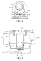
- Figure 5 shows one particular alternative variant having a spherical float 33 containing a magnetic element 333 which is free to roll, slide or otherwise move about inside the float 33. If the spherical float 33 rotates, the magnetic element 333 will seek the lowest point under gravity. Since float 33 is free to rotate, a projection 354 may be provided to housing cover 352 in place of the ridges 134 provided to the float itself in the first embodiment, in order to discourage adhesion of the float to the cover.
- such a projection can also be used in conjunction with the barrel-shaped float of the previous embodiment, either singly or as a plurality of projections, and the projections can be provided either on the float as in the previous embodiment, on the cover as in the present embodiment, or to both.
- a spherical float is self-cleaning and does not become fouled by contaminants such as hair. More particularly, the spherical shape of the float allows the float to rotate arbitrarily during use, for example due to turbulent eddies in the waste water, which action of rotation dislodges contamination on the surface of the float.
- the float may be provided as an egg shape, an oblate or prolate spheroid, an acorn shape, a puck shape or any other shape that the designer might select.
- the above-described confining structure in the form of cap 14 is only one of several possible confining structures by which the float may be arranged to be freely movable within the confines of a confining structure. Accordingly, a number of further exemplary embodiments are provided hereinbelow to assist the reader in appreciating the breadth of the different arrangements that the confining structure may take.
- top portion 413 has a shortened extended portion 413a while bottom portion 412 is provided with a cylindrical confining structure comprising spherical tube 44 in combination with filter insert 115.
- a spherical float 33 containing, within its inner void, magnetic element 333.
- a magnetic sensor 12 is provided beneath the base of the bottom portion 412.
- the cylindrical confining tube 44 is positioned directly above sensor 12. Cylindrical tube 44 is provided with small apertures throughout its surface to allow waste water to enter the confining structure such that the waste water level inside the cylindrical confining structure is the same as that in chamber 41. Use of a plurality of apertures advantageously avoids blocking of a single aperture by the float.
- water entering the gulley causes float 33 to rise, lifting magnetic element 333 away from sensor 12.
- the float is retained within the confines of the confining structure by filter insert 115 which prevents the float escaping out of the top of the gulley.
- the float 33 will be beyond a predetermined distance from the magnetic sensor 12, such that sensor 12 then provides a signal to the pump to operate. Accordingly, water is withdrawn from the chamber until such point at which the water level decreases below lower edge 417a, at which time the float 33 will have fallen to within the predetermined distance, whereupon the pump, no longer receiving the signal to operate from the sensor, will cease operating.
- FIG. 7 shows a further alternative embodiment wherein, rather than being confined by a cylindrical confining structure, a funnel-shaped confining structure is provided comprising funnel-shaped member 54 in combination with top portion 513 and filter insert 115 to constrain float 33 relative to sensor 12, with the degree of confinement in the horizontal plane increasing as the water level decreases.
- the funnel-shaped member 54 is here provided with small apertures to allow waste water to enter.
- the float 33 is retained within the confines of the confining structure by filter insert 115 and top portion 513, which prevents the float 33 escaping out of the top of the gulley.
- the funnel-shaped confining structure of the embodiment in Figure 7 permits the float more lateral freedom when the gulley is relatively full, allowing it to be violently displaced sideways to dislodge contaminants in the turbulent flow entering the gulley, while ensuring that, when accuracy is required as the float descends to the predetermined position at which activation of the pump is required, the magnetic field experienced by the sensor 12 due to the magnetic element 333 becomes sufficiently repeatable.
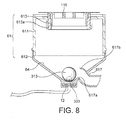
- Figure 8 shows another variant in which the confining structure is provided as an inner surface of the chamber 61, namely an inner surface 64 of bottom portion 612 and an inner surface of main portion 611, in combination with filter insert 115.
- the inner surface 64 of bottom portion 612 is provided in an inverted conical form such that float 33, at its lowest point, rests in a centered fashion above magnetic sensor 12.
- outlet 617 On one side of the bottom portion is provided outlet 617, partially covering which, is provided guard protrusion 617b.
- the function of guard protrusion 617b is to deflect float 33 away from outlet 617 as the waste water level descends, so as to avoid blockage of the outlet by the float 33 under suction from the pump P.
- Guard protrusion 617b shown in cross-section in Figure 8 , is provided in three dimensions as a hook or barb which does not have appreciable extent around the circumference of bottom portion 612 or indeed appreciable width-wise extent when compared with the width of outlet 617. Instead, guard protrusion 617b is provided having sufficient circumferential extent only to deflect float 33 from the opening of outlet 617a whilst ensuring that the float will generally be guided smoothly towards sensor 12 as the waste water level falls.
- the cap 14 or other separate confining structure is not necessary as, when the water level falls, the float will be centred over the magnetic sensor by the decreasing diameter of the conical walls acting as the confining member.
- the confining structure is provided by ribs extending radially inwards from the walls of the chamber or by confining buffers extending vertically from the bottom portion.
- Such constructions can define a variety of confines in which the float can freely move, such as cylindrical, tapered, funnel-shaped, or many other potential shapes within the freedom of the skilled person to select.
- Figure 9 shows a gulley similar to that of Figure 6 save that the confining structure is not provided as a separate structure but rather as the inner surface 74 of the chamber 71 in combination with filter insert 115.
- Bottom portion 712 has a flat base, beneath which is located magnetic sensor 72.
- magnetic sensor 72 has an extended form comparable in horizontal extent to the bottom surface 712a of bottom portion 712. The ball is therefore free to move anywhere within the confines of the chamber 71.
- sensor 72 is provided in the extended form to provide sensor coverage to the complete bottom surface 712a of bottom portion 712.
- sensor 72 has mounted thereon a plurality of sensor elements 721, which, in the present embodiment, are provided as reed switches. These are not only provided in the cross-sectional direction, but are provided to cover the surface of the sensor 72 in a regularly spaced fashion, for example, on a grid layout or in a radially concentric pattern.
- sensor elements 721 are wired in parallel. Accordingly, when magnetic element 333 comes within a predetermined perpendicular distance of the sensor 72, the reed switch 721 closest to the magnetic element 333, namely, that reed switch directly perpendicularly beneath the magnetic element, will close, being subject to a relatively greater magnetic field than the other reed switches on sensor 721. Since the reed switches are wired in parallel, closing any one of them is sufficient to generate a short-circuit condition which is employed as the control signal for activating the pump.
- the exemplary configuration of magnetic element 133 in the embodiments above is only one out of several options, in that the magnetic element may be provided as a ball (as shown), a pellet, a ring, a plate, or some other shape.
- the material of the magnetic element could be a magnetised metal, such as iron, or a magnetic ceramic or similar.
- the magnetic element may even be provided as a magnetic composition included in the constituents of the material from which the float 13 is formed, for example as a magnetic material dispersed in a polymer from which the float is formed. The important criterion is that a magnetic interaction between the sensor 12 and the magnetic element in the float 13 is dependent upon the distance therebetween. gulley.
- one further variant is to provide the magnetic sensor in the float and a magnetic element at some position in the chamber.
- the effect would be equivalent to the embodiments previously described, in that relative movement of the float and the sensor on the basis of the level of the waste water would control the pump.
- such an embodiment would provide either a tethered float to provide power to and to receive signals from the sensor inside the float by means of a cable in the tether, or the float could be provided with a battery and a wireless transmitter for communicating the state of the sensor to the pump.
- Wireless power transmission to the floating sensor e.g. by induction, could also be provided. While such a variant is not presently preferred, it nevertheless falls within the scope of the present invention, and may be a viable alternative in some situations in which there is no space to run cable alongside the outlet hose.
- the senor 12 is provided in the bottom portion of the gulley.
- one or more sensors may also be provided at other locations in the gulley: on the sides or on the top of the chamber or the cap 14, for example. Many variants in sensor placement are possible within the scope of the invention.
- illuminable indicator in another modification, variance in placing of the illuminable indicator, and the illuminable devices which are included in it, is possible.
- a single bi-colour LED 161 is positioned on the sensor 12.
- the LEDs 161, 162 are located directly underneath the rim of the cap 14. If the cap 14 is made of a sufficiently transparent material, illumination in this manner will cause the cap 14 to act as a light guide, channelling the light from the LEDs 161, 162 to the top of the gulley.
- illuminable indicators 161, 162 may be provided to the bottom portion 112 of the gulley as shown in Figure 10c . Such a situation may be preferable when it is necessary to make cap 14 or housing cover 152 from a light-blocking material.
- a controller acts as an intermediary between the magnetic sensor, the flow sensor, the pump and the illuminable indicator.
- the controller may be provided together with the magnetic sensor and the indicator in the gulley; however, variants are possible where such a controller is positioned intermediate between the gulley and the pump or at some other location, such as at the pump itself.
- the communications links between pump, magnetic sensor, indicator, controller and flow sensor may be implemented by wired links, wireless links, or any combination thereof.
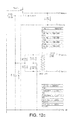
- an embodiment of the present invention may be provided without any illuminable indicator (as in the embodiments of Figures 6 and 9 ), and in such a situation the circuit diagram of Figure 11 and Figure 12 , divided into Figures 12a , 12b , and 12c for clarity, may be provided as the sensor circuit and pump controller circuit, respectively.
- All elements of the described embodiments may preferably be constructed from ABS plastic, except for the O-rings 183 and 153 which may preferably be constructed from butyl rubber, magnetic element 121 which is formed preferably from magnetised ferrite, and sensor 12 and illuminable indicator 16 which are preferably provided as conventional electronic constructions on a conventional printed circuit board connected to the pump by conventional multicore low-voltage cable 123.
- a further modification would be to control the speed of the pump P, rather that simply the on/off state of the pump, on the basis of the sensor output.
- the detection electronics for measuring the output of the sensor element may be provided at the pump, rather than at the gulley, or in an intermediary controller.
- kits of parts may be provided comprising one or more of a bottom portion , a sensor , a confining structure and a float to adapt an existing gulley.
- kit may also comprise the cover of the housing in order to implement various embodiments of the present invention.
- the kit of parts may be specifically configured to convert a particular variety of commodity gulley to be an embodiment of the invention, or the kit may be provided with a range of elements to convert one or more of a commensurate range of commodity gulleys to be an embodiment of the invention.
- the bottom portion may be formed integrally with the main portion as a dedicated unitary gulley.
Landscapes
- Engineering & Computer Science (AREA)
- Health & Medical Sciences (AREA)
- Public Health (AREA)
- Life Sciences & Earth Sciences (AREA)
- Hydrology & Water Resources (AREA)
- Water Supply & Treatment (AREA)
- Environmental & Geological Engineering (AREA)
- Epidemiology (AREA)
- General Health & Medical Sciences (AREA)
- Structural Engineering (AREA)
- Control Of Positive-Displacement Pumps (AREA)
- Water Treatment By Electricity Or Magnetism (AREA)
Applications Claiming Priority (1)
| Application Number | Priority Date | Filing Date | Title |
|---|---|---|---|
| GB1003408A GB2478288A (en) | 2010-03-01 | 2010-03-01 | Shower tray or wet-room gulley with magnetic sensor and float |
Publications (2)
| Publication Number | Publication Date |
|---|---|
| EP2363540A2 true EP2363540A2 (de) | 2011-09-07 |
| EP2363540A3 EP2363540A3 (de) | 2015-10-14 |
Family
ID=42125804
Family Applications (1)
| Application Number | Title | Priority Date | Filing Date |
|---|---|---|---|
| EP11156152.8A Withdrawn EP2363540A3 (de) | 2010-03-01 | 2011-02-28 | Automatische Duschwanne oder Feuchtraumabfluss |
Country Status (2)
| Country | Link |
|---|---|
| EP (1) | EP2363540A3 (de) |
| GB (1) | GB2478288A (de) |
Cited By (6)
| Publication number | Priority date | Publication date | Assignee | Title |
|---|---|---|---|---|
| EP2604161A3 (de) * | 2011-12-12 | 2016-10-19 | I.C.B. Innovations-Center-Bad GmbH & Co. KG | Installationsanordnung |
| WO2017176188A1 (en) * | 2016-04-04 | 2017-10-12 | Foolproof Ab | A fluid transferring device and a method for mounting such a device |
| WO2021025607A1 (en) * | 2019-08-06 | 2021-02-11 | Orbital Systems Ab | Leakage detector system |
| WO2022229290A1 (de) * | 2021-04-28 | 2022-11-03 | GANG-WAY GmbH Gesundheitszentrum und Fachbetrieb für barrierefreies Wohnen | Verfahren zum steuern einer pumpe, steuerungsvorrichtung, duschanordnung und speichermedium |
| WO2024079214A3 (de) * | 2022-10-11 | 2024-06-06 | Gang-Way Gmbh | Abwassersystem für eine sanitäre anordnung und sanitäre anordnung |
| EP4461887A1 (de) * | 2023-05-09 | 2024-11-13 | DLP Limited | Elektronisch gesteuertes duschsystem mit ausfallsicherer rückkopplungsverbindung |
Families Citing this family (2)
| Publication number | Priority date | Publication date | Assignee | Title |
|---|---|---|---|---|
| GB2483917B (en) * | 2010-09-24 | 2015-03-18 | Fabricon Prec Ltd | Liquid drainage receptacle |
| CN109098261B (zh) * | 2018-08-29 | 2020-09-11 | 徐津 | 一种侧滑磁吸式防臭排水阀芯及排水设备 |
Family Cites Families (7)
| Publication number | Priority date | Publication date | Assignee | Title |
|---|---|---|---|---|
| CH512028A (de) * | 1969-07-19 | 1971-08-31 | Bucher Rene | Elektromagnetisches Ablaufventil |
| DE3607466A1 (de) * | 1986-03-07 | 1987-09-24 | Blum Albert | Pumpenaggregat mit einer niveauschalteinrichtung |
| GB2310374B (en) * | 1994-11-01 | 1997-11-05 | Antoni Harold Nikolas Gontar | Apparatus for draining a shower tray |
| DE29812132U1 (de) * | 1998-07-08 | 1998-09-10 | Hanning & Kahl GmbH & Co., 33813 Oerlinghausen | Pumpe mit schwimmerbetätigter Abschaltautomatik |
| GB2355653B (en) * | 1999-08-27 | 2004-03-31 | Macro Marine Ltd | Improvements in shower installations |
| GB0004996D0 (en) * | 2000-03-02 | 2000-04-19 | Munster Simms Engineering Limi | Shower drain trap |
| GB2421055B (en) * | 2004-12-09 | 2007-02-14 | Dlp Ltd | Pumped waste |
-
2010
- 2010-03-01 GB GB1003408A patent/GB2478288A/en not_active Withdrawn
-
2011
- 2011-02-28 EP EP11156152.8A patent/EP2363540A3/de not_active Withdrawn
Non-Patent Citations (1)
| Title |
|---|
| None |
Cited By (7)
| Publication number | Priority date | Publication date | Assignee | Title |
|---|---|---|---|---|
| EP2604161A3 (de) * | 2011-12-12 | 2016-10-19 | I.C.B. Innovations-Center-Bad GmbH & Co. KG | Installationsanordnung |
| WO2017176188A1 (en) * | 2016-04-04 | 2017-10-12 | Foolproof Ab | A fluid transferring device and a method for mounting such a device |
| WO2021025607A1 (en) * | 2019-08-06 | 2021-02-11 | Orbital Systems Ab | Leakage detector system |
| CN114207400A (zh) * | 2019-08-06 | 2022-03-18 | 轨道系统公司 | 泄漏检测器系统 |
| WO2022229290A1 (de) * | 2021-04-28 | 2022-11-03 | GANG-WAY GmbH Gesundheitszentrum und Fachbetrieb für barrierefreies Wohnen | Verfahren zum steuern einer pumpe, steuerungsvorrichtung, duschanordnung und speichermedium |
| WO2024079214A3 (de) * | 2022-10-11 | 2024-06-06 | Gang-Way Gmbh | Abwassersystem für eine sanitäre anordnung und sanitäre anordnung |
| EP4461887A1 (de) * | 2023-05-09 | 2024-11-13 | DLP Limited | Elektronisch gesteuertes duschsystem mit ausfallsicherer rückkopplungsverbindung |
Also Published As
| Publication number | Publication date |
|---|---|
| GB201003408D0 (en) | 2010-04-14 |
| GB2478288A (en) | 2011-09-07 |
| EP2363540A3 (de) | 2015-10-14 |
Similar Documents
| Publication | Publication Date | Title |
|---|---|---|
| EP2363540A2 (de) | Automatische Duschwanne oder Feuchtraumabfluss | |
| US7429842B2 (en) | Control and alarm system for sump pump | |
| US6976367B2 (en) | Condensate overflow prevention apparatus | |
| US6934977B1 (en) | Toilet leak detection and overflow prevention system | |
| EP1250495B1 (de) | Überlaufsystem | |
| US5028910A (en) | Drain overflow alarm | |
| EP3418459B1 (de) | Spültoilette | |
| US20090195397A1 (en) | Fluid Detection and Containment Apparatus | |
| GB2478289A (en) | Shower tray gulley with illuminating pump status indicator | |
| WO2004013035A1 (en) | Water cooler drip tray drainage apparatus | |
| CN117062558A (zh) | 基站、清洁系统及其自检方法 | |
| KR101189785B1 (ko) | 가축사육용 급수장치 | |
| CA2912207A1 (en) | Toilet usage sensing system | |
| EP3704680B1 (de) | Verbinder für ein wassersystem | |
| JP2009030332A (ja) | 排水能力低下検知装置 | |
| GB2291710A (en) | Liquid level monitoring apparatus | |
| EP1116938A1 (de) | Multifunktional Filter mit Druck- und Durchsatzsensoren für Wasserwerke | |
| US8941503B1 (en) | Water saving alarm for use with a toilet tank | |
| JP5633814B2 (ja) | 水洗圧送式便器 | |
| JP2011043272A (ja) | 貯湯式給湯装置 | |
| CN210378890U (zh) | 一种水位检测开关 | |
| JP2013170413A (ja) | 圧送式トイレ装置 | |
| KR20150004237U (ko) | 수위조절장치의 수위감지장치 | |
| CN110833323A (zh) | 防漏水的饮水机 | |
| GB2559749B (en) | Fluid supply overflow control apparatus |
Legal Events
| Date | Code | Title | Description |
|---|---|---|---|
| PUAI | Public reference made under article 153(3) epc to a published international application that has entered the european phase |
Free format text: ORIGINAL CODE: 0009012 |
|
| AK | Designated contracting states |
Kind code of ref document: A2 Designated state(s): AL AT BE BG CH CY CZ DE DK EE ES FI FR GB GR HR HU IE IS IT LI LT LU LV MC MK MT NL NO PL PT RO RS SE SI SK SM TR |
|
| AX | Request for extension of the european patent |
Extension state: BA ME |
|
| PUAL | Search report despatched |
Free format text: ORIGINAL CODE: 0009013 |
|
| AK | Designated contracting states |
Kind code of ref document: A3 Designated state(s): AL AT BE BG CH CY CZ DE DK EE ES FI FR GB GR HR HU IE IS IT LI LT LU LV MC MK MT NL NO PL PT RO RS SE SI SK SM TR |
|
| AX | Request for extension of the european patent |
Extension state: BA ME |
|
| RIC1 | Information provided on ipc code assigned before grant |
Ipc: E03F 5/04 20060101AFI20150909BHEP Ipc: E03C 1/122 20060101ALI20150909BHEP |
|
| STAA | Information on the status of an ep patent application or granted ep patent |
Free format text: STATUS: THE APPLICATION IS DEEMED TO BE WITHDRAWN |
|
| 18D | Application deemed to be withdrawn |
Effective date: 20160415 |